
Related Manuals for Harman JBL SUB 550P


Summary of Contents for Harman JBL SUB 550P
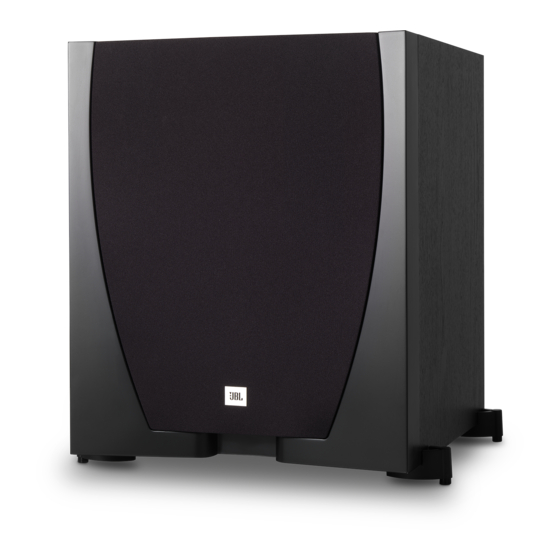
- Page 1 SUB 550P / 230 Amplifier/Subwoofer SERVICE MANUAL JBL Consumer Products 8500 Balboa Blvd. Northridge, CA. 91329 Released 2012 Rev0 01/2012 Discontinued XXXX...
-
Page 2: Table Of Contents
SUB 550P / 230 - CONTENTS - BASIC SPECIFICATIONS…………………………….….……………..2 DETAILED SPECIFICATIONS………………………………………….3 PACKAGING…………………………..…………………….……………5 CONTROLS/CONNECTIONS..…… …………… …………..……….. 6 OPERATION ………….…………………………..……….….………….8 TEST SETUP AND PROCEDURE………….……………………….…9 EXPLODED VIEW………………………….…………………………...10 230V BLOCK DIAGRAM..……………….…………………………..….11 DETAILED TROUBLESHOOTING..…………………..………… ……13 230V ELECTRICAL PARTS LIST ……….…….…….………………..14 INTEGRATED CIRCUIT/TRANSISTOR PINOUTS….…….………...21 PCB DRAWINGS………………..…………….………………………...22 230V SCHEMATICS.……….………………………………….……..…33 SUB 550P BASIC SPECIFICATIONS Low-frequency transducer:... -
Page 3: Detailed Specifications
SUB 550P / 230 Detailed Specifications LINE VOLTAGE Yes/No Hi/Lo Line Nom. Unit Notes US 120vac/60Hz 108-132 Vrms Normal Operation EU 230vac/50-60Hz 207-253 Vrms Normal operation, MOMS required Asia 100vac/50-60Hz 90-110 Vrms Normal Operation QA Test Parameter Specification Unit Limits Conditions Notes Amp Section... - Page 4 SUB 550P / 230 QA Test Parameter Specification Unit Limits Conditions Notes Efficiency & Consumption 120V Efficiency Test conducted at rated power 245WNominal Line voltage Efficiency at 1/8 of rated powe Test conducted at 31.25 WRMS Nominal Line voltage-Rated impedance 4 Ohms Standby input power 120VAC Watts @ nom.
-
Page 5: Packaging
SUB 550P / 230 Packaging (BK, CH) Item Part Number Description 1 Not for Sale Drier 2 400-000-10403-E Carton BK (230V) 400-000-10404-E Carton CH (230V) 3 Not for Sale Serial number label 4 Not for Sale Date Label 5 430-002-05495-E EPE bag 6 431-000-07533-E Top-EPE 7 431-000-07534-E Bottom-EPE 8 152-V60201A01-E Power cord (230V) -
Page 6: Controls/Connections
SUB 550P / 230 SUBWOOFER REAR-PANEL CONTROLS AND CONNECTIONS Phase Switch Input Mode Switch Level Control Crossover Control Green: On Red: Standby On/Standby Indicator Line In Connectors LFE In Connector Power Switch Power Cord Connector Phase switch: This switch determines whether the subwoofer driver’s Line In connectors: The signals from these connectors pass through the subwoofer’s internal low-pass crossover. - Page 7 SUB 550P / 230 PLACING THE SUBWOOFER The performance of a subwoofer is directly related to its placement in the listening room and its physical position relative to the other speakers in the system. Center Front Left Front Right Speaker Speaker Speaker While it is true that in general our ears do not hear directional sounds at the...
-
Page 8: Operation
SUB 550P / 230 OPERATING THE SUBWOOFER TURNING THE SUBWOOFER ON AND OFF SUBWOOFER ADJUSTMENTS: PHASE Set the subwoofer’s Power Switch to the “On” position. The subwoofer will The Phase switch determines whether the subwoofer automatically turn itself on when it receives an audio signal, and it will go driver’s piston-like action moves in and out in phase into Standby mode after it has received no audio signal for approximately with the satellite speakers. -
Page 9: Test Setup And Procedure
SUB 550P / 230 Test Set Up and Procedure Equipment needed: Function/signal generator/sweep generator Integrated Amplifier Multimeter Speaker cables General Unit Function (UUT = Unit Under Test) 1) From the signal generator, connect line level (RCA) cables to the Subwoofer Line Level Input jacks L/R on the UUT. -
Page 10: Exploded View
SUB 550P / 230 Exploded View Item Part Number Description 1 244-100-05478-0BAE Grille 2 350-HM04020D149-E Screw 3 5110G Woofer 4 373-000-05145-E Feet 5 241-100-05598-0RAE Cabinet (CH) 241-100-05598-0BAE Cabinet (BK) 6 350-AM04020D079-E Screw 7 010-7625-05381-E... -
Page 11: 230V Block Diagram
SUB 550P / 230... - Page 12 SUB 550P / 230...
-
Page 13: Detailed Troubleshooting
Sub550P/230 Troubleshooting flow chart Stand-by BD check +6V,-6V, Stand-by Start VOL. Test protection Dc voltage check ±Vcc,±15V Check U ±15Vcc ect Check transformer 168, Test limiter circuit 124, Power on check Check U LED red &blue Check vol module Check THD output &... -
Page 14: 230V Electrical Parts List
SUB 550P / 230 Part number Description Q'ty Reference Designator 010-7625-05381-E AMP JBL 250W SUB550P/230 EUP RoHS 051-A05068B-E PCB ASS'Y OF MOTHER BD(RoHS) 109-1TSC103J0-E Resistor TSC05103J (RoHS) R237, 110-12621J15-E Resistor 620Ω 1/2W ±5% 15mm(RoHS) R238, 110-16102J26-E Resistor 1K 1/6W ±5% CF 26mm TAP(RoHS) R210,R239,R264, 110-16103J26-E Resistor 10K 1/6W ±5% CF 26mm TAP(RoHS) - Page 15 SUB 550P / 230 190-16L431CLP1-E IC TL431CLP (RoHS) D115, 190-16LM324N-E I.C. LM324N (RoHS) U107, 192-027C1815GR-E Transistor 2SC1815GR TOSHIBA(RoHS) Q110,Q112,Q114,Q117, 192-028A1015GR-E Transistor 2SA1015GR TOSHIBA(RoHS) Q111,Q113,Q115, 192-1572N5551-E *Transistor FSC 2N5551 TAP (RoHS) Q109, 192-1582N5401-E Transistor FSC 2N5401 AI-PNP 350V500mA TO-92 Q108, (RoHS) 192-991SD669AL-E TransistorUTC 2SD669AL 180V 1.5ATO-126C RoHS Q116,...
- Page 16 SUB 550P / 230 130-2B471KJ03-E Capacitor 470P 1000V ±10% TAPY5P (RoHS) C07, 130-2F331MD00-E Capacitor 330pF 250V ±20% LS= 10mm (RoHS) C03, 132-103KB74-E Capacitor 0.01UF 10% 275V (RoHS) C15, 132-224KB70-E Capacitor 0.22uF 275V ±10% (RoHS) C19, 132-224KB74-E Capacitor CBB-0.22uFK 5% 275VACX2 (RoHS) C06, 135-B156MD0-E C01,...
- Page 17 SUB 550P / 230 129-A104JA03-E Capacitor 0.1U 100V ±5% MSCTAP (RoHS) C12B,C14, 130-SL681KB03-E CapacitorSL 680PF 200V (RoHS) 132-104KB50-E Capacitor0.1U ±10% 250V (RoHS) C20, 132-105KB50-E Capacitor1uF 250V ±10% (RoHS) C40, 141-C0101K50-E SMD Capacitor100pF 50V 10%1206 NP0 (RoHS) 141-C0220K50-E SMD Capacitor22pF 50V 10% 1206SMT NPO (RoHS) 1 141-C0561K50-E SMD Capacitor560pF 50V 10%1206 NPO (RoHS) 141-C5104M50-E...
- Page 18 SUB 550P / 230 110-16472J26-E Resistor 4.7K 1/6W ±5% CF 26mmTAP (RoHS) R144, 110-16473J26-E Resistor 47K 1/6W ±5% CF 26mm TAP(RoHS) R137, 110-16474J26-E Resistor 470K 1/6W ±5% CF 26mmTAP(RoHS) R143, 110-16823J26-E Resistor 82K 1/6W ±5% CF 26mm TAP(RoHS) R138, 115-H103A101-E Resistor A10K (RoHS) R286, 115-H503B405-E...
- Page 19 SUB 550P / 230 135-3105M50-E Capacitor 1U 50V ±20% TAP(RoHS) C126, 135-3106M50-E Capacitor 10uF 50V ±20% TAP(RoHS) C109,C111,C123,C129, 135-3107M16-E Capacitor 100uF 16V ±20% TAP(RoHS) C113,C115,C132,C134,C 135-3107M25-E C152, Capacitor 85℃ 100uF ±20%25V TAP LF/RoHS 135-3226M50-E Capacitor 22U 50V ±20% TAP(RoHS) C151, 139-3227M16-E Capacitor220uF 16V±20% TAP (RoHS) C131,...
- Page 20 SUB 550P / 230 180-P3024DB-E Switch ROCKER 3024-DB (RoHS) 193-0S4211-E INSULATION SPACER 42*11 (RoHS) 193-201612TR-E Isolation sink T0-220 16mm*12mm(RoHS) 236-AL-05001-0LAE AL Batten (RoHS) 302-AL-05085-1BCE AL plate 300*200*2.5MM RoHS 306-ABS-05079-0BAE Rear cover 198*298*102H (RoHS) 311-ABS-00028-0BAE Knob 46077-W P.V.C.(RoHS) 323-AL-05000-0LAE Heat-sink (RoHS) 325-FE-00400-0LAE PCB stand 58*9*13.5T (RoHS) 333-EVA-00188-0BAE EVA Gasket 170x5x1t (RoHS)
-
Page 21: Integrated Circuit/Transistor Pinouts
SUB 550P / 230... -
Page 22: Pcb Drawings
SUB 550P / 230... - Page 23 SUB 550P / 230...
- Page 24 SUB 550P / 230...
- Page 25 SUB 550P / 230...
- Page 26 SUB 550P / 230...
- Page 27 SUB 550P / 230...
- Page 28 SUB 550P / 230...
- Page 29 SUB 550P / 230...
- Page 30 SUB 550P / 230...
- Page 31 SUB 550P / 230...
- Page 32 SUB 550P / 230...
-
Page 33: 230V Schematics
SUB 550P / 230... - Page 34 SUB 550P / 230...
- Page 35 SUB 550P / 230...
- Page 36 SUB 550P / 230...
- Page 37 SUB 550P / 230...
- Page 38 SUB 550P / 230...
- Page 39 SUB 550P / 230...
- Page 40 SUB 550P / 230...
- Page 41 SUB 550P / 230...
- Page 42 SUB 550P / 230...
- Page 43 SUB 550P / 230 152PF FUSE 15uF/400V 300K 300K 4.7n/500V 1N4007 HI VOL UF302 0.1u 330u/10V 250mA 1N4007 1.1meg 0.1uF 470PF/1k 0.22u IND1 330u/10V 1N4007 UF1010 1.1meg 17mH ICSP 1N4007 0.1uF 330u/10V SF16 0.01uF 0.1u/25V 330u/10V 0.1u CON1 UF302 47uF/35V Header 2B TRANSFORMER 0.22u...
Need help?
Do you have a question about the JBL SUB 550P and is the answer not in the manual?
Questions and answers