
Summary of Contents for Barton RCL-4002
- Page 1 Ready Care Lift (RCL-4002) (RCL-4500) (RCL-6002) Operation Manual (Model RCL-4002 Shown) Rev A March 2007...
-
Page 2: Table Of Contents
TABLE OF CONTENTS Page # Warnings Warranty Ready Care Lift (Model 4002) Specifications Ready Car Lift (Model 4500) Specifications Bariatric Ready Care Lift (Model 6002) Specifications Ready Care Lift Overview Assembly Operation Ready Car Lift Overview Operation (special instructions for lifting from a vehicle Slings - Loading in a Seated Position - Loading in a Recumbent Position... -
Page 3: Warnings
If you have any questions regarding the setup or operation of the Ready Care Lift, please contact: AFFIX DEALER CONTACT INFORMATION HERE Or contact Barton Medical: 1-800-387-7103 THE READY CARE LIFT FROM BARTON MEDICAL HAS BEEN INSPECTED TO C.S.A. (CANADIAN STANDARDS ASSOCIATION) GUIDELINES. -
Page 4: Warranty
Barton Medicals’ liability under warranties is limited to replacing defective parts and does not extend to consequential damages. Warranties are voided by unauthorized repairs or modifications to the equipment. -
Page 5: Ready Care Lift (Model 4002) Specifications
READY CARE LIFT SPECIFICATIONS PRODUCT NUMBER: RCL-4002 OPERATION: Electric Actuator POWER SOURCE: 24 V (4.5 Amp) BOOM, Highest Position: 70” (178 cm) BOOM, Lowest Position: 23” (58 cm) MAXIMUM CAPACITY: 500 lbs (182 kg) OVERALL LENGTH: 45½” (116 cm) BASE/LEG WIDTH, Closed: Inside - 21¼”... -
Page 6: Ready Car Lift (Model 4500) Specifications
READY CAR LIFT SPECIFICATIONS PRODUCT NUMBER: RCL-4500 OPERATION: Electric Actuator POWER SOURCE: 24 V (4.5 Amp) BOOM, Highest Position: 65-¾” (167 cm) BOOM, Lowest Position: 29” (73.7 cm) MAXIMUM CAPACITY: 500 lbs (182 kg) OVERALL LENGTH: 45½” (116 cm) BASE/LEG WIDTH, Closed: Inside - 21¼”... -
Page 7: Bariatric Ready Care Lift (Model 6002) Specifications
BARIATRIC READY CARE LIFT SPECIFICATIONS PRODUCT NUMBER: RCL-6002 OPERATION: Electric Actuator POWER SOURCE: 2 X 12-Volt sealed, lead acid BOOM, Highest Position: 71” (180 cm) BOOM, Lowest Position: 23.75” (60 cm) MAXIMUM CAPACITY: 700 lbs. (272 kg.) OVERALL LENGTH: 53.5” (136 cm) BASE WIDTH, Closed: inside: 21”... -
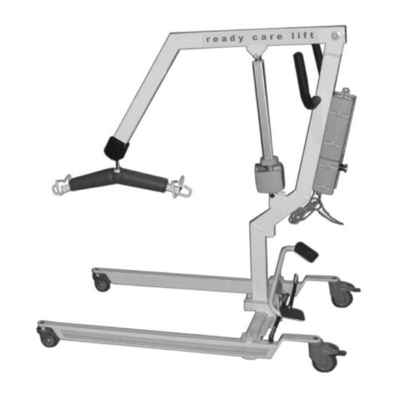
Page 8: Ready Care Lift Overview
READY CARE LIFT OVERVIEW Lift Arm Steering Handles Lift Arm End Cap Interchangeable Battery System Actuator Sling Hanger Mast (see detailed view) Rear Locking Casters VIEW A Detailed View of Foot Pedal Assembly Foot Pedal Textured Sure Grip Tie Rod End Tie Rod... -
Page 9: Assembly
ASSEMBLY 1. Without using a knife, open the carton and remove the packaging which secures the lift in the box. When removing the mast be careful as the lifting arm and actuator are fastened to the mast. 2. Once all the parts have been removed from the carton, ensure you have all the components which make up the lift. -
Page 10: Operation
OPERATION CHARGE YOUR READY CARE LIFT EVERY NIGHT USING THE CHARGER PROVIDED. 1. The lift should not be operated (more than two lifts) when the battery level indicator begins to flash yellow. Be sure to charge as soon as possible. Extended use of the battery pack when the low battery indicator is flashing may permanently affect the capacity of the batteries in the pack. -
Page 11: Ready Car Lift Overview
READY CAR LIFT OVERVIEW Sling Lift Arm Hanger Lift Arm End Cap Steering Handles Actuator Mast Rear Locking Casters... -
Page 12: Operation
SPECIAL INSTRUCTIONS FOR LIFTING FROM A VEHICLE For a vehicle extraction, the safe use of the lift requires two caregivers. With doors on both sides of the vehicle open, one caregiver can access the patient from inside the vehicle while the other works from the outside. Assess the size and shape of the patient;... -
Page 13: Loading In A Seated Position
LOADING IN A SEATED POSITION If the user is seated in a wheelchair, make sure the wheelchair is in a locked position before proceeding. If the user is in bed, either bring the head of the bed to the upright position or follow the procedure for loading in a recumbent position. -
Page 14: Loading In A Recumbent Position
LOADING IN A RECUMBENT POSITION If the user is in bed, make sure the surface is flat and adjusted to a comfortable working height. 1. Turn the user to face you and hold the sling sideways with the smooth side facing the user. -
Page 15: Positioning The Legs
POSITIONING THE LEGS Three leg positions are possible with the General Purpose Sling: open, divided and closed. The closed position is for transfers, the open and divided positions are for toileting and bathing as well as transfers. The closed position is often felt to be more dignified, controls muscle spasms and is beneficial for transfers of amputees. -
Page 16: Sling Care
The life of a sling, like that of any garment, depends on the manner and frequency of its use and laundering. Barton slings have a one year warranty. In normal institutional use, it is good practice to replace slings annually. -
Page 17: Transfers
TRANSFERS CHAIR TO BED TRANSFER Choose the appropriate sling for your resident and place it under them. (For more information on using slings please see the Slings section of this manual). Adjust the legs of the Ready Care Lift to straddle the chair. Use your left foot to push the left pedal of the leg adjustment to widen the legs to the correct width. - Page 18 TRANSFERS BED TO CHAIR TRANSFER Choose the appropriate sling for your resident. Turn the resident on their side and position the sling at their back. Spread one side of the sling out and turn the resident onto it and over further onto their side. Spread the other half of the sling out and turn the resident onto their back.
-
Page 19: Interchangeable Battery System Overview
INTERCHANGEABLE BATTERY SYSTEM OVERVIEW Battery/Charge Level Indicator Emergency Stop Plug In Ports (see below for detail view) Bottom View Of Electronics Pack Hand Control (400-125) Overview Hanger Emergency Hand Control Plug Lowering (into Electronics Pack) Charger Port Actuator Port Down Secondary Actuator Port Hand Control Port... - Page 20 INTERCHANGEABLE BATTERY SYSTEM 1. It is highly recommended that the batteries be fully charged on a daily basis. This action will greatly extend the life to the battery. 2. The Battery Pack may be charged while on the lift by inserting the charger plug into the charger port on the bottom of the Electronics Pack (see Electronics Pack Bottom View on page 14).
-
Page 21: Ibs Technical Data
IBS TECHNICAL DATA IBS-130 Complete System (Includes Battery, Electronics Pack, Hand Control and Charger) Individual Components of IBS-130 Charger (400-141) Battery Pack (400-155) Electronics Pack (400-143) Hand Control (400-125) Control Unit Voltage (actuator): 24V - DC (max 6.3A) Operating element: Hand control AC Adaptor: 28V 500mA... -
Page 22: Placing And Removing The Battery Pack
PLACING AND REMOVING THE BATTERY PACK Placing the Battery Pack on the Lift To place the battery on the electronics pack, hold the battery pack by the top handle and place your other hand on the side of the pack. Position the metal tabs on the back of the battery pack into the metal slots on the electronics pack mounting bracket. -
Page 23: Installing The Charging Station
INSTALLING THE CHARGING STATION (400-157) 2 13/16” (72 mm) 1 1/4” (32 mm) 4 3/8” 13/16” (111 mm) (21 mm) 6 3/8” (162 mm) The above schematic shows the location of all of the mounting holes. The wall mounted charging station should be fastened to the wall using 1/4” screws with the appropriate wall anchors (will vary depending on your facility’s wall structure). -
Page 24: Ready Care Lift Scale (Optional)
READY CARE LIFT SCALE (OPTIONAL) Scale Hanger Cover Hanger Weight Display Lbs/Kg Indicator Switch Between On Button Kgs and Lbs. Zero Button... -
Page 25: Scale Attachment (Optional)
SCALE ATTACHMENT (OPTIONAL) Parts required to install: 1 - 3/8" N.C. x 2" hex head bolt 1 - 3/8" N.C. nylock nut 2 - 3/8" x 1/2" buttite spacer Slide lift arm end cover up onto the lift arm and remove the nut and bolt which secures the hanger and remove the hanger. -
Page 26: Scale Operation (Optional)
SCALE OPERATION (OPTIONAL) Once installed, the scale becomes a permanent part of the Ready Care Lift. To weigh a patient: Hang the appropriate sling on the hanger ensuring that the sling does not touch the floor. Push the ON button to power the scale. There will be a display of 0-0-0-0 across the window. -
Page 27: Ready Care Lift - Major Components
READY CARE LIFT - MAJOR COMPONENTS (Lift Arm 101-074) (Bariatric Arm 101-074B) (Ready Car Lift Arm 102-671) Mast Hanger Assembly 101-901 (see detail view) (Bariatric 101-081B) (Car Lift 102-669) Boom End Cover (100-039) Foot Pedal (101-065) 350 mm Actuator (Bariatric 101-065B) (400-131) Tie Rod Assembly (see detail view) -
Page 28: Hanger Assmebly - Detail View
HANGER ASSEMBLY - DETAIL VIEW Hanger Cover (101-045) Retaining Clip (100-049) Hanger (101-173) 1.015 id x 1.5 od Nylon Washer (100-072) Hanger Pin (100-070) TIE ROD ASSEMBLY - DETAIL VIEW 1/2" Threaded Rod with Cover (100-008) 1/2" Tie Rod End (Long) 1/2"... -
Page 29: Interchangeable Battery System - Bariatric
INTERCHANGEABLE BATTERY SYSTEM - BARIATRIC Battery Pack Handle Emergency Battery Pack Stop Button Emergency Lowering Electronics (depress with Pack small object) Battery Level/ Charge Indicator HAND CONTROL OVERVIEW ELECTRONICS PACK BOTTOM VIEW Charger Port Down Port for Port for Hand Actuator Plug-In Control Plug-In... -
Page 30: Placing And Removing The Battery - Bariatric
PLACING AND REMOVING THE BATTERY PACK - BARIATRIC Placing the Battery Pack on the Lift To place the battery on the electronics pack, hold the battery pack by the top handle and place your other hand on the back of the pack. Place the battery on top of the electronics pack and push the battery toward the mounting plate until the metal tab on the top of the battery pack locks into place. -
Page 31: Maintenance
MAINTENANCE The following is a checklist of the areas of the READY CARE LIFT that should be inspected on a regular basis. It is recommended to inspect the lift monthly or bi-monthly. This will depend on frequency of use. Any part which appears worn or wearing should be replaced immediately for safety of caregiver and patient. -
Page 32: Troubleshooting
TROUBLESHOOTING 1. Ready Care Lift will not operate in either direction: -ensure the actuator (motor) is plugged in and secure -emergency switch is turned off (turn button clockwise) -check battery level indicator -ensure the hand control is connected to the electronics pack -check for cuts in the hand control wire 2. - Page 34 By returning this card, I acknowledge receiving the aforementioned product in good working order and physical appearance. Any errors made during installation or unpacking of the aforementioned product, if installed or unpacked by a party other than Barton Medical or a Barton appointed agent, shall be the responsibility of the customer and will not be covered under the warranty.
Need help?
Do you have a question about the RCL-4002 and is the answer not in the manual?
Questions and answers