
Related Manuals for Digitus DN-13020


Summary of Contents for Digitus DN-13020
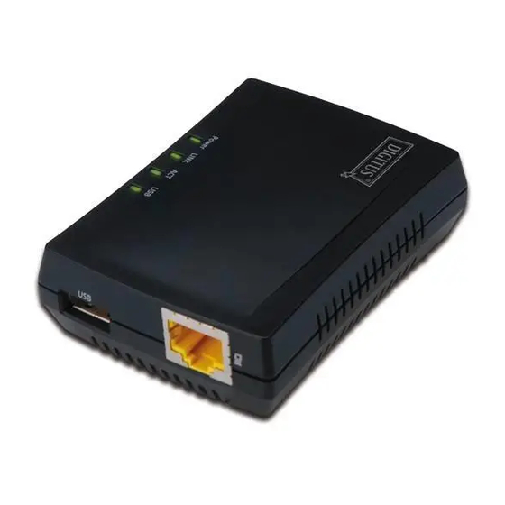
- Page 1 USB 2.0 Multifunction Network Server DN-13020 DN-13021 DN-13022 DN-13023 User Manual DN-13020 • DN-13021 DN-13022 • DN-13023...
-
Page 2: Table Of Contents
Table of Contents CHAPTER1 PRODUCT OVERVIEW ..................4 Package Contents ................4 Product CD ..................4 1.2.1 Start-up Procedures ..............4 Supported USB Devices ..............4 CHAPTER2 BASIC INSTALLATION ..................5 Connecting the Hardware ..............5 Wireless connection ................5 2.2.1 Preliminary ................. - Page 3 CHAPTER5 THE SERVER’S WEB PAGES ................. 28 Introduction ..................28 Using the Server’s Web Pages ............28 5.2.1 Displaying Server Status ............28 5.2.2 Setting up Server Configuration ..........29 CHAPTER6 TROUBLESHOOTING ..................32 LED Indicators ................32 Firewall ................... 32 CHAPTER7 RESTORE FACTORY DEFAULTS ..............
-
Page 4: Chapter1 Product Overview
Chapter1 Product Overview Package Contents Verify that nothing is missing from the package by using the checking list below. Please contact your dealer if anything is missing or damaged. All packing materials are recyclable. Please confirm the items in the package below: This Server ... -
Page 5: Chapter2 Basic Installation
Chapter2 Basic Installation 2.1 Connecting the Hardware 1. Make sure that your USB devices are switched off and that the Server’s Power Adapter is disconnected. 2. Connect the USB devices to the USB ports with the USB cables. 3. Connect the Server to the network with a twisted-pair category 5 cable, 10baseT or 100baseTX. - Page 6 If the wireless parameters are not correct or not set yet, you have to use LAN to access USB Device Server Control Center. 4. If the tool finds USB device servers in your local area network, then you have to select a server from the server list.
- Page 7 6. Login with administrator ID (default: admin) and its password (default: admin). 7. Click Wireless icon. 8. In order to join an existing wireless network, you have to set the correct SSID, and the correct security method with the correct key information. 9.
- Page 8 10. If the wireless network is secured by WPA-PSK or WPA2-PSK, the key formats, shared key and encryption must be set correctly.
-
Page 9: Assigning An Ip Address To The Server
11. Click Submit to save your settings. And the server will reboot. 12. You have now finished the procedure of setting the wireless parameters. After properly configuring the wireless parameters, you can remove the network cable and reboot the DN-13021/DN-13023. DN-13021/DN-13023 will then connect to your wireless network. -
Page 10: Ip Address
2.3.2 IP Address Unless you are assigning an IP address using DHCP, you must obtain an unused IP address from your network administrator. 2.3.3 Methods for Setting the IP Address You can set the IP address of your Server using one of the following methods, depending on your network operating environment: Automatic IP Address Assignment ... - Page 11 Double click the highlighted server (or click the “Configure Server” button) to get the server’s web pages. Click CONFIG icon. Login with administrator ID (default: admin) and its password (default: admin).
- Page 12 Click the button corresponding to your choice of IP setting methods (static or dynamic using DHCP). When assigning a static IP address you also have to define Subnet Mask. Click Submit to save your settings. And the Server will reboot. You have now finished the procedure of setting the IP address.
-
Page 13: Chapter3 Using The Usb Device Server
Chapter3 Using the USB Device Server Introduction The goal of this produce is to provide the USB device server in a single product. We developed a new technology called “NetUSB” to achieve this goal. Basically, the “NetUSB” is a “USB over IP” technology that transparently redirects all USB packets to TCP/IP network channel. -
Page 14: Installation Of Usb Device Driver
Installation of USB Device Driver Some USB devices, like printers or MFPs (multifunction printers), require to install vendor-supplied driver (usually on CDROM). For those USB devices that do not need to install driver, please skip this section. Insert the CDROM into the CD drive and run the “autorun” program. Follow the instructions of the installation program to install driver. -
Page 15: Using The Usb Device Server
Now, the installation program will detect the USB device and continue to install driver. After the installation is completed, click the USB device in the Control Center and then click the “Disconnect” button to disconnect the USB device. Now the driver of your USB device is installed. Using the USB Device Server In the Control Center, click the USB device server that has the desired USB device attached. - Page 16 Now, PC will detect the plug-in of the USB device. The “connect” operation is a software operation that simulates an actual USB device plug-in. That is to say, when you do a “connect” operation in the Control Center, PC can then detect a USB device’s plug-in, although actually you do not plug in any USB device.
-
Page 17: Auto-Connect Printer
Auto-Connect Printer The method described in section 4.5 is so-called manual-connect, which means users must manually connect the USB device before using that device, and must manually disconnect the USB device after using the device, otherwise nobody else can connect this device. However, for printers and scanners (and MFPs), the USB device server supports auto-connect so users don’t need to manually connect/disconnect. - Page 18 D. Choose the desired printer. The desired printer must be the Windows printer (this is a logical printer) that matches the printer attached on the USB device server (this is a physical printer). Then click the “Apply” button. Then, the printer will be marked as an “Auto-Connected Printer” in red. If you choose “Auto-Connected Printer List”...
- Page 19 Then try to issue a print job to the desired printer. You will see the Control Center will automatically do a connect operation. Then, the print job will be issued to that printer. G. Even you already properly setup an auto-connected printer, the Control Center must be running (in the background) while a print job is issued.
-
Page 20: Network Scanner
Network Scanner For NetUSB scanning, we recommend you use Network Scanner as the following steps. In the Control Center, click the USB device server that has the desired MFP (or scanner) attached. Click the desired MFP (or scanner). C. Click the “Network Scanner” button. Then you can see that the Control Center will automatically do a “connect”... -
Page 21: Usb Storage
D. Choose one of TWAIN or WIA item. Click “OK”. The following window will appear. Follow the usual steps to do scanning. After the scanning, close the “Auto-Connect Scanner” window. At this moment, Control Center will automatically do a disconnect. USB Storage You must use “manually connect”... -
Page 22: Request To Connect
You can see the storage icon in the system tray. Then just use the new disk as a general disk. After you finish the disk operations, click the storage icon in the system tray and choose “Safely remove USB Mass Storage Device” to remove the USB storage, as the following figure. -
Page 23: Quitting The Control Center
At this moment, the user on the TEST computer will see the following window, indicating that another computer – TESTES is requesting to use the HP printer. The user will choose to accept or reject. If accepted, the Control Center on TEST will automatically disconnect the device and the Control Center on TESTES will automatically connect that device. -
Page 24: Chapter4 File Server
Chapter4 File Server This chapter describes the file server function of the Server which allows USB storage devices to be shared across a network by using SMB: NetBIOS over TCP/IP and FTP protocol. Preliminary 1. This product supports a file format of FAT12/16/32 and NTFS. However, the “write” operation on NTFS is only supported in NetUSB mode. - Page 25 The Server supports Windows codepages. If users want to communicate files using FTP client tool or SMB on Windows 98/Me/2000 with the Server, they have to set their Server codepage to be same as the codepage that their Windows PC is using. SMB on Windows 98/Me/2000 Configuring the Server’s Codepages Users can use the following methods to set the Server’s codepage.
-
Page 26: Using Shared Storages By Smb/Cifs Method For Windows
Using Shared Storages by SMB/CIFS Method for Windows Connect a USB storage device to this product. Select My Network Places. Click Display the Computers of Workgroup. Double click Microsoft Windows Network icon. Double click the Workgroup that the Server belongs to. The default Workgroup name is “WORKGROUP”. -
Page 27: Using Shared Storages By Smb/Cifs Method For Windows
Using Shared Storage by FTP Methods for Windows Use Microsoft IE to the shared USB Mass Storages Open Microsoft IE In Web Address List, enter command: “ftp://Server’s Server Name“ or “ftp://Server’s IP address”. If you have changed the default FTP port : 21 to the new value, you have to add the new port number in the tail of command as “ftp://Server’s Server Name: ftp port”... -
Page 28: Chapter5 The Server's Web Pages
Chapter5 The Server’s Web Pages 5.1 Introduction The Server runs the http server, httpd on TCP port: 80. Users may use the web pages to see the Server’s system status and configure the Server. Using the Server’s Web Pages 5.2.1 Displaying Server Status Click on the “STATUS”... -
Page 29: Setting Up Server Configuration
5.2.2 Setting up Server Configuration To set up the Server configuration, click on the “CONFIG” icon ad then the system will request user to enter administrator (default: admin) and password (default: admin) to login. General Configuration Server Information: You have to set the Server Name, which is the name to represent the Server. - Page 30 TCP/IP: You have to set the Server’s TCP/IP configuration to connect TCP/IP network. Please see Chapter 3 Basic Installation for more details. Storage Access Mode: Set storage access mode as server or NetUSB mode. UPnP Setting: Enable or disable the UPnP function. ...
- Page 31 Administrator: You can change administrator name and password. If you forgot administrator name and password, you must perform Restore Factory Default action by plugging in the power adaptor while pressing the Init button. Please refer to the chapter “Restore Factory Defaults”. Administrator: enter your desired administrator name.
-
Page 32: Chapter6 Troubleshooting
Chapter6 Troubleshooting This chapter provides useful information to help you resolve difficulties that you may experience with your Server. Fault symptoms, possible causes, and remedial actions are provided within a quick reference table. This Server’s USB ports only support MFPs, printers, scanners, mass storage, and USB cameras. -
Page 33: Chapter7 Restore Factory Defaults
Chapter7 Restore Factory Defaults You may restore the Server’s default parameters by one of the following methods. Using the Server’s Web Pages Go to the Server’s web page and click CONFIG Enter administrator (default: admin) and password (default: admin). Click Maintenance. Click Factory Default. -
Page 34: Using Init Button
Using Init Button Plug in the power adaptor while pressing the Init button until LED indicators of USB1 and USB2 blink. After that, plug off the power adaptor and then plug in the power adapter again to restart the Server. Finally, the Server will operate using the Factory Default values. Default Parameters List TCP/IP ... - Page 35 PC’s TCP/IP such that PC and the Server belong to the same LAN, i.e. PC’s IP is 192.168.1.xxx and subnet mask is 255.255.255.0. (DIGITUS doesn’t have this utility.) 4. Click Upload Image. 5. Wait for Image Uploading to finish and then click Close.
-
Page 36: Chapter9 The Init Button
Chapter9 The Init Button The Init button is used for maintenance: Simultaneously press Init button and turn on (by plugging in the power adaptor) the Server until USB1 and USB2 LED indicators simultaneously blink. After that, the Server will do the following tasks: Perform a Factory Default restoration of the server, which will restore most of the parameters and settings to factory default values. -
Page 37: Chapter10 Fcc Statement
Chapter10 FCC Statement Federal Communication Commission Interference Statement This equipment has been tested and found to comply with the limits for a Class B digital device, pursuant to Part 15 of the FCC Rules. These limits are designed to provide reasonable protection against harmful interference in a residential installation.
Need help?
Do you have a question about the DN-13020 and is the answer not in the manual?
Questions and answers