Table of Contents
Advertisement
Advertisement
Table of Contents

Related Manuals for TV One C2-2000 Series


Summary of Contents for TV One C2-2000 Series
- Page 1 C2-2000 Series Video Processor Operation Manual...
-
Page 3: Table Of Contents
TABLE OF CONTENTS DISCLAIMER ....................1 Regulatory Agency Acceptance................1 FCC Statement....................1 Manual Version Information................. 2 Manual Copyright Notice ..................2 IMPORTANT SAFETY INSTRUCTION............3 CAPABILITY, DEVICE FEATURES AND PRODUCT FEATURES..... 13 Device Capabilities.................... 13 Device Features ....................14 PRODUCT IMAGES ........ - Page 4 The High Level Menu Structure ................. 26 Group Names and Descriptions................. 27 Items Associated with the Adjust outputs group..........27 Items Associated with the Adjust windows group..........29 Items Associated with the Adjust keyers group..........33 Items Associated with the Adjust sources group ..........34 9.6.1 RGB Source Menu Items...................
- Page 5 15.1 DVI-I connector ....................55 15.2 HD15 connector ....................55 15.3 RS232 / D9 socket..................... 56 15.4 4 Pin mini-DIN S-video connector (YC) input............. 56 15.5 Multi-way audio connector................. 56 16 SPECIFICATIONS ..................57 16.1 Video Inputs ...................... 57 16.2 Computer Input....................
-
Page 6: Disclaimer
DISCLAIMER This product is intended for professional and/or home use. This product is not intended for use in a medical environment and does not have the required certifications for such use. Similarly, use aboard any aircraft or spacecraft while in flight or as an adjunct to any surface, airborne or marine navigation system or any offshore marine activity, including control of any watercraft, or any use similar to those specifically herein mentioned is prohibited. -
Page 7: Manual Version Information
Release Date: July, 2006 Manual Copyright Notice This Operation Manual is the intellectual property of TV One, ©2006. No portion of this manual may be copied or reproduced in any manner or by any means, including, but not limited to electronic and electro-mechanical, without the express... -
Page 8: Important Safety Instruction
IMPORTANT SAFETY INSTRUCTION To insure the best from this product, please read this manual carefully. Keep it in a safe place for future reference. To reduce the risk of electric shock, do not remove the cover from the unit. No user serviceable parts inside. Refer servicing to qualified personnel. 2.1 Power and connections This unit is not disconnected from the AC power source as long as it is connected to the wall outlet. - Page 9 Slots and openings in the sides of the unit are provided for ventilation. To ensure reliable operation, avoid obstruction of these openings and ensure the unit is installed in a well-ventilated area. 2.6 Intellectual property Some IC chips in this product include confidential and/or trade secret property. Therefore you may not copy, modify, adapt, translate, distribute, reverse engineer, reverse assemble or decompile the contents thereof.
- Page 10 2 IMPORTANT: CONSIGNES DE SECURITE Afin de tirer le meilleur de ce produit, merci de lire attentivement ce manuel. Gardez-le dans un endroit sûr pour pouvoir le consulter à nouveau. Afin de réduire le risque de choc électrique, ne retirez pas l’unité de sa protection. Aucune pièce réparable par l’utilisateur à...
- Page 11 2.5 Aération Les rainures et les ouvertures sur les cotés de l’unité servent à l’aérer. Pour permettre une utilisation sûre, évitez d’obstruer ces ouvertures et assurez-vous que l’unité est installée dans un endroit bien aéré. 2.6 Propriété intellectuelle Certaines puces IC dans ce produit contiennent des éléments propriétaires confidentiels et/ou des secrets commerciaux.
-
Page 12: Instrucciones Importantes De Seguridad
2 INSTRUCCIONES IMPORTANTES DE SEGURIDAD Para sacar el mejor provecho de este producto, léase este manual con detenimiento. Guárdelo en un lugar seguro para poder hacerle referencia en el futuro. Para reducir el riesgo de calambre, no quite la cubierta del aparato. No hay piezas utilizables dentro. - Page 13 Este aparato se debe instalar en un lugar seco y fresco, lejos de fuentes de calor excesivas, la vibración, el polvo, la humedad y el frío. 2.5 Ventilación El aparato viene provisto de ranuras y agujeros en los lados para la ventilación. Para asegurar una operación eficaz, se debe evitar la obstrucción de estos agujeros y también asegurar que el aparato se instale en una zona con adecuada ventilación.
- Page 14 2 WICHTIGE SICHERHEITSVORSCHRIFTEN Lesen Sie diese Bedienungsanleitung bitte sorgfältig, um Ihr Produkt optimal nützen zu können, und bewahren Sie sie zum späteren Nachschlagen an einem sicheren Ort auf. Entfernen Sie bitte keinesfalls die Abdeckung, um der Gefahr eines Stromschlags vorzubeugen. Im Inneren des Geräts befinden sich keine Teile, die vom Benutzer gewartet werden können.
- Page 15 Das Gerät sollte an einem kühlen, trockenen Ort aufgestellt werden, fern von übermäßiger Wärme, Vibrationen, Staub, Feuchtigkeit und Kälte. 2.5 Belüftung Seitliche Schlitze und Öffnungen sorgen für die Belüftung des Geräts. Um die ordnungsgemäße Belüftung zu gewährleisten, dürfen diese Öffnungen nicht verdeckt werden.
- Page 16 2 BELANGRIJKE VEILIGHEIDSINSTRUCTIES Lees deze handleiding zorgvuldig door om het beste uit uw product te halen. Bewaar het op een veilige plek voor raadpleging in de toekomst. Haal nooit het omhulsel van de eenheid af, dit om de kans op een elektrische schok te verminderen.
- Page 17 2.5 Ventilatie De sleuven en openingen aan de zijkant van de eenheid zijn voor ventilatie. Zorg er voor dat de eenheid op een goed geventileerde plek geïnstalleerd wordt zodat deze betrouwbaar werkt. 2.6 Intellectueel eigendom Sommige IC chips in dit product bevatten vertrouwelijke informatie en/of fabrieksgeheimen.
-
Page 18: Capability, Device Features And Product Features
CAPABILITY, DEVICE FEATURES AND PRODUCT FEATURES Device Capabilities ® The C2-2000 series uses the proprietary CORIO 2 Engine to perform its functions, ® ® being the second generation of the successful CORIO products. The CORIO technology is a powerful toolset for any application requiring high quality video signal conversion or image manipulation. -
Page 19: Device Features
Ultimate flexibility The C2-2000 series’ output signal format flexibility assures that the Native Resolution of virtually any display can be matched. Because of the resolution calculator (included in the Windows® Control Panel), even new resolutions can be added to the unit. -
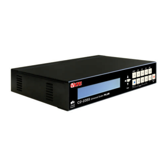
Page 20: Product Images
PRODUCT IMAGES Your C2-2000 product should look like one of the units below. Each unit has a different main function (Down Converter, Video Scaler, Universal Scaler) and a subsequently different ability to process video signals. -
Page 21: Front Panel Controls
The range of buttons on the front of the unit provides the user with quick access for selecting a variety of inputs and features. Since all the units in the C2-2000 series are different, not all of the descriptions below will be applicable to the unit in question. -
Page 22: Multi-Directional Switch
See ‘Adjust outputs’ menu details. Sets Lock mode to Lock & Mix, to overlay onto the current Lock source. Use with the KEY and FADE buttons for more flexibility. press will swap foreground and background. See ‘Adjust outputs’ menu details. Activate picture-in-picture mode. -
Page 23: Switching Units Between Different Resolutions (Ntsc, Pal And Default)
hold the STANDBY/ON and the multi-directional switch in together until two beeps are heard. All stored settings except resolutions are lost when the unit is reset. A Firmware update is the only way to perform a complete factory reset (including resolution data). 5.3.4 Switching units between different resolutions (NTSC, PAL and Default) -
Page 24: Video Inputs And Outputs
VIDEO INPUTS AND OUTPUTS The C2-2000 series has a number of different inputs and outputs – see earlier front and rear panel diagrams to see what is available on your unit. Computer & Video inputs PC/HD inputs can accept: Analog RGBHV ... -
Page 25: Computer & Video Outputs
Computer & Video outputs The PC/HD output can use: Analog RGBHV RGsB (sync on green) RGBS (separate sync at TTL levels) YUV/YPbPr (including tri-level). However, please note that on some units such as Down Converters, the RGB output is there just to loop the PC image through to the PC monitor. - Page 26 On the back of audio-equipped units are 5 x 3-way connector blocks. These can be removed individually (with care), or can be left in-situ whilst connections are made (by releasing each terminal using a small screwdriver, and then by clamping it back down again once a new cable has been inserted).
-
Page 27: Unpacking And Installation
If you did not receive the correct adaptor, DO NOT attempt to modify it. Instead, immediately contact your dealer or contact TV One at the sales office nearest to your geographic location and request the proper adaptor. -
Page 28: Initial Operation And Test Of Video Scalers
Disconnect the cable going from a Personal Computer’s Monitor to the Personal Computer. Connect the output from the PC video card (the PC connector formerly used by the monitor cable) to the PC input on the rear panel of the unit. Next, take the cable from the PC monitor and connect it to the PC/HD output –... - Page 29 Next, take the cable from the PC monitor and connect it to the PC/HD output. Then connect the AC Power Adaptor to a working AC outlet, turn on the PC, monitor and then your unit. Provided you have not changed anything from the Factory Defaults and the monitor will display output 1024x768 @ 60Hz, then your PC output will be seen on the PC monitor –...
-
Page 30: Infra-Red Remote Control
INFRA-RED REMOTE CONTROL Your unit is provided with an infra-red remote control, whose buttons have the following functions: Resets back to power-on defaults Stores current Selects input: settings 1/2/3=RGB/CV/YC Enables Keyer Enables Lock & Mix mode Fades in/out Starts AutoSet Locks the IR &... -
Page 31: Menu Layout And Settings Adjustment
MENU LAYOUT AND SETTINGS ADJUSTMENT From here on, we’ll be looking at the menu structure employed in the C2-2000 series and, more importantly, the individual menu items that allow you to take advantage of the power of the unit. You’ll be using the multi-directional switch and the Liquid Crystal Display (LCD) to view the options and settings available to you. -
Page 32: Group Names And Descriptions
There are two screens that appear before the Group Menus (sub-menus) are accessed. CORIO2 TV One The first is the ‘welcome’ display shown above indicating the model of the unit. www.tvone.com SW: 65. PT: 12, BT: 13 Moving to the next menu item displays the firmware information screen (the numbers on your unit will be different to those shown). - Page 33 800 x 600 60Hz Lock mode [Off] [RGB1] This menu item allows the lock mode to be selected and the lock source to be defined. The top line of the display shows the current detected resolution of the selected lock source (RGB1 in this example). The lock mode can be either Off, Genlock or Lock &...
-
Page 34: Items Associated With The Adjust Windows Group
Adjust outputs Output type [RGBHV] This menu item allows you to select the type of signal output your unit will provide. Types of output vary depending on the resolution selected and include various types of component signals Y/R-Y/B-Y or YPbPr, the full range of RGB type signals RGBHV, RGBs and RGsB (Sync on green). - Page 35 Adjust windows Zoom level % [ 100] Changing this option, sets the amount of picture magnification you wish to use for the window Source. You are provided with the options to zoom the image from 100% to 1000% (10x zoom). Adjust windows H/V zoom % [100] [100]1.333...
- Page 36 Adjust windows Shrink level% [ 50] [On] Shrink Level determines the percentage of the monitor’s total available screen space that the selected Window image occupies. Adjustment is provided for a reduction down to 10% of the overall output size. In most cases, this feature is used for picture-in-picture (PIP) when a background image is being used (for units with overlay abilities).
- Page 37 left as “Simple”, the H/V components of Zoom and Shrink are adjusted equally i.e. H is equal to V. Adjust windows Flicker Reduction [Low] The Flicker Reduction menu item will only appear if you have selected a low resolution interlaced output such as PAL or NTSC. If you are using CV or YC outputs, this adjustment may be of interest, particularly when you have line drawings or similar fine detail.
-
Page 38: Items Associated With The Adjust Keyers Group
feature off. The unit will not allow an unstable image to appear on the screen if De- glitch is left On. Items Associated with the Adjust keyers group Please note that not all units have this sub-menu – it is only present on units with overlaying abilities. -
Page 39: Items Associated With The Adjust Sources Group
Adjust keyers Y Key min/max [ 0] [ 32] The Min/Max parameters are used to select what range of Y (luminance/grey-scale) values are made transparent within the selected window/lock source. In order to key out part of an image, start with the max value and increase it until the required lighter parts within the window/lock source disappear. -
Page 40: Rgb Source Menu Items
Source: RGB1 Source to adjust [RGB1] This menu item selects the input connection for which you want to make adjustments to. As in the image above, changes will only be made to the source connected to RGB1. Once the selection has been made, all changes made using the following operating parameters will only apply to the selected input. - Page 41 used with an optional Audio Switcher such as the A2-2000, S2-Series, or on units with Audio inputs and outputs. The default for the first 4 video inputs is to assign each video input an audio input from 1 to 4. For example, video input 1 receives audio input1, video input 2 receives audio input 2 etc.
-
Page 42: Cv & Yc Source Menu Items
YUV - also know as YPbPr and common for 720p and 1080i formats, where a sync signal is present on the Y signal Source: RGB1 RGB contr. [100] [100] [100] This menu item lets you adjust the individual RGB or YUV/YPbPr signals, in case one component is at a different contrast to other, or if they all need to be boosted or lowered. -
Page 43: Items Associated With The Adjust Ethernet Group
Source: YC1 Bright [100] Contrast [100] Adjust the Brightness and Contrast of the image to your requirement. Source: YC1 Satur [100] Hue [0] Saturation is the amount of color present in the image. Hue is the color “tint” parameter and the adjustment range is +90 degrees through to -90 degrees with 0 being the default. -
Page 44: Items Associated With The Adjust Resolutions Group
This parameter has three possible states: On, Off and Auto. On and off manually control the Ethernet capability of the unit. When in Auto mode, if a valid Ethernet connection is present, remote control of the unit will automatically default to Ethernet and control via RS-232 is disabled. - Page 45 Important Cautionary Information DO NOT ADJUST THESE ITEMS UNLESS YOU’RE CERTAIN YOU KNOW WHAT YOU’RE DOING! THE ONLY METHOD TO UNDO CERTAIN CHANGES IS TO UPDATE THE FIRMWARE. TRY USING THE AUTOSET, SHRINK, SHRINK POS, TL & BR ADJUSTMENTS FIRST. Making adjustments here risks creating a non-standard resolution that is not displayable on a monitor.
- Page 46 The H.freq.fine (Horizontal Sync Frequency) adjustment provides the option for changing the Horizontal Sync timing Frequency in 1 Hz steps. Use this option to fine tune after using the course adjust. Please note that the internal sync generator may be unable to generate the exact frequency you want.
-
Page 47: Items Associated With The System Group
respect to the Horizontal Sync pulse and the width of the Back Porch have a direct bearing on where the active (visible) portion of the image begins. Do not attempt this adjustment without monitoring the results with an oscilloscope. 800 x 600 60 Hz H/V Sync [ 128] x 4 There are standards for all current computer and broadcast resolutions that specify... - Page 48 designators and cannot be changed by the user however both designators are important to support personnel. System SW date: 2006-7-11 This is an information page showing when the currently installed software was released. The information is useful to the user as he or she compares the date to the support website information describing the current software release.
- Page 49 System Advanced Menus [Off] When turned on, the previously explained Adjust resolutions menu structure is exposed. The default condition is ‘Off’, to prevent accidental changes. System RS232 baud rate [57600] This menu item allows the adjustment of the serial baud rate used for RS-232 communications.
- Page 50 System Hours in Use This is another informational display for usage audit purposes.
-
Page 51: Rs232 Control
RS232 CONTROL 10.1 Connection Your unit is fitted with a standard ‘D9’ socket allowing it to be controlled from a computer or other type of terminal or console with a similar interface. Most computers fitted with an RS232 port, known as a ‘COM’ port, will have a ‘D9’ plug on them. -
Page 52: Common Operations
COMMON OPERATIONS This section provides step by step instructions for some common operations. 11.1 Operation of the Keyer Some units come equipped with a very powerful Luminance and Chrominance Keyer. The Keyer can take some time to master and below is a breakdown and series of simple steps to help you master the Keyer’s operation When adjusting the values, please bear in the mind the following: The Y value is the Luminance value, so 0 is black and 255 is very bright (white). - Page 53 to decrease the ‘min’ values and increase the ‘max’ values to broaden the range of colors keyed out. At this point, only the key color should remain transparent.
-
Page 54: Troubleshooting And Technical Support
TROUBLESHOOTING AND TECHNICAL SUPPORT If problems are experienced, please read through the symptom topics below in order to resolve the problem. After doing so, if you still need to, contact Technical Support at http://www.tvone.com/support. Please have the following details of the problem handy: Whether the problem happens only at specific times or has only just started occurring (and what other things have changed at the same time). -
Page 55: There Is Excessive Flicker On The Output
12.4 There is excessive flicker on the Output. Try using a different Flicker reduction mode. Turning the contrast down and the brightness up on the output device can have a large effect on flicker. Or try adjusting the brightness and contrast of the source input by selecting the Input adjust menu. -
Page 56: The Rgb Input Is Selected But The Image Is Rolling Or Pink
12.11 The RGB input is selected but the image is rolling or pink. Check the Adjust sources menu and confirm that the input type and sync method is set correctly. (Having YUV input selected, instead of RGBHV often causes this problem). -
Page 57: Return Procedure
13.2 To return a unit for repair First contact TV One using the http://www.tvone.com/support website. Support personnel will determine whether a return to the factory is the appropriate solution. If that’s the case, a Return Authorization Number will be issued. You should... - Page 58 Please clearly state the return number on the outside packaging and on any accompanying documentation. This will greatly speed up processing. IMPORTANT: DO NOT return a unit for warranty repair without first obtaining a Return Authorization Number. No action will be taken on a unit returned in warranty for repair without a Return Authorization Number.
-
Page 59: Warranty Policy
Should this product, in TV One’s opinion, prove defective within this warranty period, TV One, at its option, will repair or replace this product without charge. Any defective parts replaced become the property of TV One. This... -
Page 60: Connector Pinouts
CONNECTOR PINOUTS 15.1 DVI-I connector PIN# SIGNAL PIN# SIGNAL T.M.D.S DATA 2- HOT PLUG DETECT T.M.D.S DATA 2+ T.M.D.S DATA 0- T.M.D.S DATA 2/4 SHIELD T.M.D.S DATA 0+ Not used T.M.D.S DATA 0/5 SHIELD Not used Not used DDC CLOCK Not used DDC DATA T.M.D.S CLOCK SHIELD... -
Page 61: Rs232 / D9 Socket
14. V sync 15. SCL (input & output linked) 15.3 RS232 / D9 socket 1. N/C 2. TX (Transmit data) 3. RX (Receive data) 4. N/C 5. GND (Signal return) 6. N/C 7. CTS (Clear to send) 8. RTS (Request to send) 9. -
Page 62: Specifications
SPECIFICATIONS See product front and rear diagrams for details of product I/O. Not all units in the C2-2000 series have all the inputs and outputs listed here. 16.1 Video Inputs Input impedance: 75 Ohm Television standards supported: NTSC and PAL... -
Page 63: Computer Outputs
16.4 Computer Outputs DVI-D output on DVI-I connector, supporting up to 108MHz maximum clock/pixel rate (1280x1024 @ 60Hz) – higher pixel rates are sub-sampled to 108MHz. Analog output impedance 75 Ohm Analog RGBHV, RGBS, RGsB, YPbPr (0.7v RGB / 1.0v sync-tip to white) Connectors: HD-15 and/or 5 x BNC Analog PC Resolutions: any up to 2048x2048 (user adjustable) Analog HDTV Resolutions: any up to 1080p... -
Page 64: Warranty
16.8 Warranty Limited warranty: 2 years parts and labor 16.9 Regulatory Compliance Main unit conforms to FCC, CE, RoHS 16.10 Environmental Operating temperature: +4 to +45 deg.C (+40 to +113 deg. F) Operating humidity: 10% to 85%, non-condensing Storage temperature: 0 to +60deg.C (+32 to +140deg. F) Storage humidity: 10% to 85%, non-condensing 16.11 Power Requirement External power supply: 12V DC @1A maximum. -
Page 65: Contact Information
CONTACT INFORMATION Should you have and questions or require assistance with this product in areas not covered by this manual, please contact TV One at the appropriate location shown below: TV One USA TV One Latin America 1350 Jamike Drive... - Page 66 We Provide Solutions TV One USA TV One Latin America 1350 Jamike Drive 8260 NW 27th Street Erlanger, KY 41018 Suite 404 – Transal Park Miami, FL 33122 Tel 859-282-7303 Fax 859-282-8225 Tel 305-418-9305 sales@tvone.com Fax 305-418-3096 www.tvone.com sales.latinoamerica@tvone.com www.tvonela.com...
Need help?
Do you have a question about the C2-2000 Series and is the answer not in the manual?
Questions and answers