Table of Contents
Advertisement
ALLEN&HEATH
2 2
M M
i i
c c
r r
o o
p p
h h
o o
n n
2
M
i
c
r
o
p
h
o
n
3 3
S S
t t
e e
r r
e e
o o
L L
i i
n n
3
S
t
e
r
e
o
L
i
n
4 4
Z Z
o o
n n
e e
O O
u u
t t
p p
4
Z
o
n
e
O
u
t
p
R R
o o
u u
t t
i i
n n
g g
M M
a a
t t
R
o
u
t
i
n
g
M
a
R R
e e
m m
o o
t t
e e
C C
o o
n n
R
e
m
o
t
e
C
o
n
D D
u u
c c
k k
i i
n n
g g
D
u
c
k
i
n
g
E E
x x
p p
a a
n n
d d
e e
r r
E
x
p
a
n
d
e
r
I I
n n
s s
t t
a a
l l
l l
e e
r r
A A
s s
s s
I
n
s
t
a
l
l
e
r
A
s
s
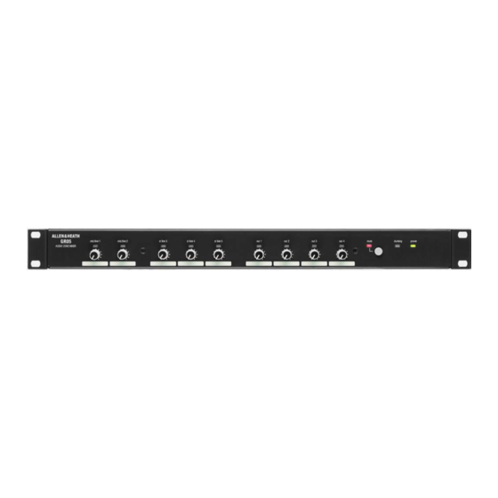
GR05
Audio Zone Mixer
e e
I I
n n
p p
u u
t t
s s
e
I
n
p
u
t
s
e e
I I
n n
p p
u u
t t
s s
e
I
n
p
u
t
s
u u
t t
s s
u
t
s
r r
i i
x x
t
r
i
x
t t
r r
o o
l l
t
r
o
l
i i
g g
n n
a a
b b
l l
e e
i
g
n
a
b
l
e
USER GUIDE
INSTALLATION
Publication AP3181
Introduction ......................... 3
Welcome to the GR05 ......... 4
The System.......................... 5
Overview of Installation ....... 6
Positioning the Unit ............. 8
Connecting Power............... 9
Front Panel .......................... 10
Rear Panel ........................... 11
Mic/Line Inputs .................... 12
Line Inputs ........................... 14
Outputs ................................ 15
Level Control........................ 16
Remote Control ................... 17
Ducking................................ 18
Expander In/Out .................. 20
Specification ........................ 21
Block Diagram ..................... 22
Configuration Sheet............. 23
Advertisement
Table of Contents

Related Manuals for ALLEN & HEATH GR05


Summary of Contents for ALLEN & HEATH GR05
-
Page 1: User Guide
ALLEN&HEATH GR05 Audio Zone Mixer Introduction ......3 Welcome to the GR05 ..4 The System......5 Overview of Installation ..6 Positioning the Unit ..... 8 Connecting Power....9 Front Panel ......10 Rear Panel ......11 Mic/Line Inputs ....12 Line Inputs ...... - Page 2 NOTE: Any changes or modifications to the unit not approved by Allen & Heath could void the compliance of the unit and therefore the user’s authority to operate it. GR05 User Guide AP3181 Issue 5 Copyright © 2008 Allen & Heath Limited. All rights reserved Whilst we believe the information in this guide to be reliable we do not assume responsibility for inaccuracies.
-
Page 3: Safety Warning
Protect from excessive dirt, dust, heat or cold and Do not connect sources of AC or DC power or the output vibration when operating, shipping or storing the unit. of power amplifiers directly to the audio input or output connectors. GR05 User Guide... -
Page 4: Welcome To The Gr05
The GR05 has 2 microphone inputs and 3 stereo line inputs. These can be assigned to 4 zone outputs configurable in mono or stereo pairs and controlled by front panel or remote level controls. -
Page 5: The System
The System The following diagram shows the GR05 in a typical sound contractor installation. This combines paging microphones with background music sources feeding up to 4 speaker zones. An alarm interface and battery backup are included to ensure crowd control in the event of a fire or power failure. Remote level controls are wall mounted for local speaker control. -
Page 6: Overview Of Installation
Before starting make sure you have read this User Guide and understand the full capabilities of the GR05. Plan the complete system first to decide how the GR05 should be configured. Make sure you know the operating levels of the equipment to be interconnected. -
Page 7: Line Inputs
Rack or Desk Mount Each has a pair of RCA phono sockets for Left and Right The GR05 is shipped with the two rack ears and its inputs. For mono sources only one need be used. To plastic feet fitted. The unit will fit into a 1U space in a mono a stereo source use the routing options as standard 19”... -
Page 8: Positioning The Unit
Positioning the Unit The GR05 is built into a compact all steel case. This can fit into a standard 1U 19” rack space with the mounting ears provided. Alternatively the unit can be desk or shelf mounted by removing the ears. -
Page 9: Connecting Power
Connecting Power The GR05 has a built in mains operated power supply unit. This converts and conditions the mains voltage to the DC voltages required to power the circuits. An additional DC power input is available on the rear panel expander/remote connector. -
Page 10: Front Panel
= Mains power on only = Backup power on only To remove the knob simply pull it forwards. To refit the Yellow = Mains and backup power on knob align the knob hole with the flat on the control spindle. GR05 User Guide... -
Page 11: Rear Panel
Sets the gain of the microphone pre-amplifier. This to the microphone by adjusting the rear gain trimmer for control can be set as a preset or locked out after correct reading on the front signal meter. adjustment. GR05 User Guide... - Page 12 To configure the unit switch off power, remove the top cover and adjust the links and trimmers as shown. Power may be applied for setting up the trimmers. Avoid the power supply components shown greyed out on the diagram. GR05 User Guide...
-
Page 13: Gain Trim
Although the shelf peaks at 70Hz manuals. Alternatively disconnect the cable screen at frequencies up to 600Hz can be affected. Use this in the GR05 input. Do not remove the GR05 mains earth conjunction with the lo-cut filter to tailor the low end connection. -
Page 14: Line Inputs
Make which would normally by routed direct so that it can sure that all the routing links are fitted correctly. Set duck or mute other music sources. unrouted links to the OFF position. GR05 User Guide... -
Page 15: Outputs
+4dBu by adjusting internal trimmers. Mid position Routing provides 0dBu output. You can also use these trimmers to adjust the balance between the outputs. This shows the two paths each input signal can take to each output, VCA or DIRECT. GR05 User Guide... -
Page 16: Level Control
This system avoids operator confusion by locking away will affect the signal. Set the link to SW or OFF as redundant controls. shown. Note that the switch will have no effect if it has been disabled as described previously. GR05 User Guide... -
Page 17: Remote Control
For each output to be remote controlled set the link to specified 0 to +10V.DC to these inputs. REM(1,2,3,4) as shown. Note that signals routed to the output via the DIRECT path will not be affected by the remote control. GR05 User Guide... -
Page 18: Ducking
(-10dB), normal (-20dB) or to turn off ducking is not required the link should be fitted on one the signal (MUTE). Release time is either fast or slow. pin only as shown. Set the links as shown. GR05 User Guide... - Page 19 Pin 1 as shown. Set the depth and release link options as shown. For alarm override and jukebox replay the recommended settings are depth = MUTE (off), release = SLOW. EXPANDER / REMOTE GR05 User Guide...
- Page 20 Alternative Output Connections Adding More Inputs The four zone output signals that appear on the XLR This example shows a ‘slave’ GR05 connected to a connectors are duplicated on the expander/remote D- ‘master’ unit to provide more inputs. In this case the type connector.
-
Page 21: Specification
Better than 90dB shutoff, 80dB interchannel Noise Mic EIN -128dB referred to 150ohm source Line preamp -91dBu Mix noise all routed < -86dB Mechanical Width 483mm (19”) Height 44/49mm (1.75”) 1U Depth 260mm (10.3”) Weight Unpacked 4kg (9lb) Packed 5kg (11lb) GR05 User Guide... - Page 22 GR05 User Guide...
- Page 23 GR05 User Guide...
- Page 24 GR05 User Guide...
Need help?
Do you have a question about the GR05 and is the answer not in the manual?
Questions and answers