Advertisement
Table of Contents
- 1 Limited One-Year Warranty
- 2 Conditions of Warranty
- 3 Service and Technical Support
- 4 Safety Warning
- 5 Adjusting the Levels
- 6 Specification
- 7 Installation
- 8 Connecting Power
- 9 Control Function
- 10 Input Section
- 11 Master Section
- 12 MIC Inputs
- 13 Line Inputs
- 14 Channel Direct Outputs
- 15 Main Outputs
- 16 Alarm Override
- Download this manual
Advertisement
Table of Contents

Subscribe to Our Youtube Channel
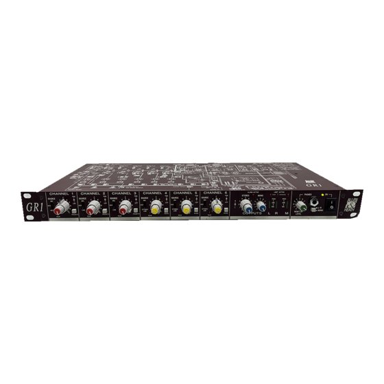
Summary of Contents for ALLEN & HEATH GR1
- Page 1 ALLEN&HEATH 24 Input 3 output Zone Mixer USER GUIDE (Installation) PUBLICATION: AP2057...
-
Page 2: Limited One-Year Warranty
LIMITED ONE YEAR WARRANTY This product has been manufactured in the UK by ALLEN & HEATH and is warranted to be free from defects in materials or workmanship for a period of one year from the date of purchase by the original owner. To ensure the high level of performance and reliability for which this equipment has been designed and manufactured please read this User Guide before use. -
Page 3: Service And Technical Support
This user guide presents a quick reference to the function, application and installation of the GR1. For further information on the basic principles of audio system installation and engineering please refer to one of the specialist publications available from bookshops and audio equipment dealers. -
Page 4: Adjusting The Levels
The use of low impedance sources significantly reduces interference pick-up. Check the cables for correct wiring to avoid problems with phase reversal and unreliable connection. The GR1 follows the convention for XLR pin 2 and jack tip = signal hot (+). Always use balanced cables when connecting to phantom powered microphones. -
Page 5: Specification
SPECIFICATION 0 dBu = 0.775 Volts RMS 0 dBV = 1 Volt RMS Line level options: +4dBu (high level), 0dBu, -10dBV (300mV low level) INTERNAL OPERATING LEVEL: -2 dBu FREQUENCY RESPONSE: 20Hz to 30kHz +0/-1dB INTERNAL HEADROOM: ... +23 dB MAX OUTPUTS: ...... -
Page 6: Installation
INSTALLATION The GR1 fits into a 1U space in a standard 19" rack system. Alternatively the unit may be mounted into a cabinet or plinth, or simply used free standing. Dimensions shown are case size in millimeters. Allow extra space as nec- essary for the front controls (add 26mm) and for the rear connectors. -
Page 7: Control Function
CONTROL FUNCTION input section LEV & PAN The top control adjusts the signal level to the L, R, & M mix. The lower control adjusts the position in the stereo image. In the centre click position, the L & R have equal signal levels. - Page 8 The GR1 offers unique flexibility in its ability to be configured to satisfy the exact requirements of each installation. This is done by setting internal jumper links and calibration trimmers which determine the operating levels, signal routing, and mode of operation of the ducking, alarm and compressor/limiter systems.
-
Page 9: Mic Inputs
EARTHING THE AUDIO SYSTEM The chassis is connected to mains earth via the power cord. FOR SAFETY REASONS NEVER REMOVE THE EARTH WIRE FROM THE MAINS PLUG. Audio 0V is connected to mains earth by the internal ground lift link op- tion. -
Page 10: Line Inputs
(pre) or after (post) the chan- nel level control. PRE may be used to feed the channel signals to additional GR1 units for zone expansion, or for signal monitoring. POST may be used for recording feeds, effects sends etc. Two channels are set on one bank of links. -
Page 11: Main Outputs
ROUTING THE CHANNELS TO THE OUTPUTS Each of the 6 channels may be routed as required to a combination of the 3 outputs L, R and M to feed up to 3 mono zones or one stereo and one mono zone. The L and R post level outputs may also be routed to the M output for situations where a L+R sum is required. - Page 12 PRIORITY DUCKING SYSTEM The GR1 offers a flexible ducking system that allows one or a combination of the 3 mono channels to duck (override) the level of the other channels by reducing their level by a pre-determined amount. For example this may be used for voiceover anouncements where the background music is dimmed by the microphone signal level.
- Page 13 REMOTE CONTROL OF THE LEVELS Each of the 6 channels and the main L,R and M outputs are fed through high performance VCA (voltage controlled amplifier) circuits. These are controlled individually either by the front panel level controls or by external DC voltages connected to the REMOTE DC connector according to the setting of the internal jumper links as shown below.
-
Page 14: Alarm Override
To allow automatic control of the system by an alarm recording or emergency announce- ment the GR1 includes a comprehensive alarm override feature. When activated the front panel ALARM ACTIVE LED lights and the 3 main outputs are automatically switched to the selected alarm audio source. - Page 15 EXPANDING THE INPUTS WITH SYS-LINK The number of input channels feeding the outputs may be expanded by connecting GR1 units together using the SYS-LINK system. A single cable connects the L,R and M outputs of one unit to the buss inputs of the next.
- Page 16 EXPANDING THE OUTPUTS WITH SYS-LINK The number of outputs may be expanded by connecting GR1 units together using the SYS-LINK system. This may be used to provide more zone feeds from the 6 input channels. A single cable connects the 6 channel DIR outputs of one unit to the AUX inputs of the next.
- Page 17 USER GUIDE...


Need help?
Do you have a question about the GR1 and is the answer not in the manual?
Questions and answers