ALLEN & HEATH DLive CTi-1500 - Control Surface for MixRack Manual
- Getting started manual (17 pages)
Advertisement
Read before starting
Safety instructions
Before starting, read the Important Safety Instructions printed on the sheet supplied with the equipment. For your own safety and that of the operator, technical crew and performers, follow all instructions and heed all warnings printed on the sheet and on the equipment panels.
System operating firmware
The function of the dLive Surface is determined by the firmware (operating software) that runs it. Firmware is updated regularly as new features are added and improvements made.
 Check www.allen-heath.com for the latest version of dLive firmware.
Further information
Please refer to the Allen & Heath website for further information, knowledgebase and technical support. For more information on dLive setup and mixing functions please refer to the dLive Firmware Reference Guide available for download at www.allen-heath.com.
You can also join our Allen & Heath Digital Community to share knowledge and information with other dLive users.
Register your product
Register your product online at www.allen-heath.com/register.
Packed items
Check you have received the following:
- dLive CTi-1500 Surface
- CAT5 Cable (2m)
- Getting Started Guide AP12150
- Safety Sheet
- IEC mains lead
Introduction
dLive is a distributed digital mixing system providing a uniquely flexible solution for any live sound application. It separates the mix engine from the control surface, putting the audio and processing where it is needed, and offering a host of control and audio networking possibilities. Refer to the Allen & Heath website to find out more about dLive.
The MixRack is the heart of any dLive system. It houses the XCVI processing core complete with audio I/O, control and audio networking ports. The Surface is effectively a network controller for the MixRack, with the addition of built-in audio I/O and audio networking ports. DX Expanders can be added to the system for extra I/O.

dLive Surfaces
There are different sizes of dLive Surface available. The CTi-1500, C1500, C2500 and C3500 feature the same I/O and differ only in the number of faders and touchscreens. The S3000, S5000 and S7000 offer more I/O, an extra I/O Port, redundant power supplies and dual redundant gigaACE and DX connections. Refer to their Getting Started Guide for further detail.
dLive Surface features at a glance:
- Fully assignable layout
- Single or twin 12" capacitive touchscreen
- Gesture control – pinch, swipe, drag 'n drop
- Configurable widget areas for Scenes, meters, FX and more
- 19 assignable SoftKeys (26 on S3000, S5000, S7000)
- Engineer's Wedge and IEM fader strips
- Comprehensive multipoint metering
- Daylight visibility
- USB stereo recording and playback
Rear Panel

- Mic/Line inputs – 6x recallable preamps for balanced or unbalanced microphone and line level signals. Gain, Pad and 48V are digitally controlled within the preamp.
The PP indicator lights up when phantom power voltage is detected at the socket, whether internally or externally sourced.
Any socket can be patched to any Input Channel using the I/O orProcessing / Preamp screen. - I/O Port – Audio interface port, 128x128 channels. Fit one of the option cards available for system expansion, digital mic splitting, recording or distributed audio networking. Refer to www.allen-heath.com for a list of available option cards.
iLive / GLD option cards (M-Dante, M-Waves, M-ES-V2, M-ACE, M-MADI) can be used with dLive when fitted with the M-DL-ADAPT 'letter-box' adapter. This provides a 64x64 48kHz interface with built-in Sample Rate Conversion.
Use the I/O screen to patch signals from or to the I/O Ports.
- Digital inputs – Stereo AES3 input (32kHz – 96kHz sampling rate). Sample Rate Conversion can be bypassed.
Any socket can be patched to any Input Channel using the I/O or Processing / Preamp screen. - Line outputs – 6x line level, balanced XLR outputs. Nominal level +4dBu.
Signals can be patched to any output socket using the I/O screen. - Digital outputs – Stereo AES3 output (48kHz or 96kHz switchable).
Signals can be patched to any output socket using the I/O screen. - Power Supply – Mains IEC socket, fuse and On/Off rocker switch.
Heed the safety warnings printed on the panel.
A plastic P-clip cable clamp is provided to secure the mains cable. Slot the cable in or lock it in place using a star Torx© T20 screwdriver to refit the clamp around the cable.
- Status indicators – Power ON indicator. The Ready indicator lights up when the output sockets are ready to pass audio after power up.
- Phones - Standard 1/4" and 1/8" jack sockets. Another pair of sockets is located under the armrest.
- Screen Out – VGA port for connection of an external monitor. The external monitor can mirror either of the touchscreen views or display a third view. Use the Surface / Screen screen to configure.
External touchscreens are not supported.

- Kensington Lock - A slot for fitting standard Kensington anti-theft security devices.
- DX link – EtherCon port for connection of a DX expander over Fast Ethernet (IEEE 802.3 Layer 2 compliant). A single Cat5e (or higher) cable carries 32x32 channels of 96kHz audio and control.
Use the I/O screen to patch signals from or to the DX expanders. - Word Clock I/O - BNC connector for syncing from an external audio clock or providing a clock to other devices.
- Network – 2 RJ45 Gigabit Ethernet ports. Connect a laptop or a wireless router to use with dLive Editor or iOS apps. All devices on the network must have compatible IP addresses.
- gigaACE link – MixRack to Surface link over Gigabit Ethernet (IEEE 802.3 Layer 2 compliant). A single Cat5e (or higher) cable carries bidirectional 96kHz audio and control.
- Audio Sync Locked – Indicates a valid clock source.
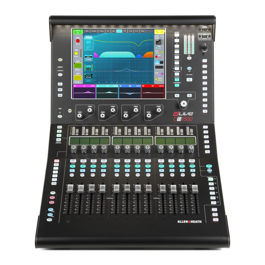
Front Panel

- Touchscreen – Single 12" capacitive touchscreen with gesture control and daylight visibility. Read the Harmony UI paragraph below for further information.
- Main / PAFL meters – LCR meters with PAFL active indicator. Press PAFL Clear to cancel any active PAFL.
- USB ports – The upper port is dedicated to stereo WAV file recording and playback. The lower port is for data transfer of Show files, Libraries, event logs and firmware updates.
- Phones – Analogue volume control for the headphones output.
- SoftKeys – 19 user assignable keys. Assign functions using the Surface / Control / SoftKeys screen.
- Talkback – Press to Talk latching or momentary key and Talk Active indicator. Hold down Assign and press any master Mix key to assign.
- Assign – Hold down and press a strip Mix key to toggle its assignment to the active Mix on or off.
Pre/Post – Hold down and press a strip Sel key to toggle sends to the active Mix pre or post fade.
Toggle all channels on/off or pre/post by pressing a master Mix or Sel.
Assignments and pre/post settings for the selected channel or Mix are also available in the Routing screen. - Layers – Navigate 6 layers of fader strips per bank. The red peak indicators light up when any channel in the associated layer is within 5dB of clipping, so you can keep a check on signal activity across the layers.
- Fader Strips – Provide control of Input channels, FX returns, Mix masters, DCAs, engineer's Wedge / IEM monitor, or MIDI. Read the Fader Strip paragraph below for further information.
The strip layout is user assignable and stored in Scenes. Use the Surface / Control / Strip Assign screen to edit the strip layout. - Phones - Standard 1/4" and 1/8" jack sockets are located under the armrest.
- Safes – Hold down and press a strip Mix key to make the channel safe from Scene recall. To make only a selection of parameters safe, use the Scenes / Scene Safes screen.
Freeze in Layers – Hold down and press a strip Mix key to lock a channel in place across all layers.
GEQ on Faders – Presents the GEQ for a selected mix on the faders. Press to toggle between high and low frequencies, and to exit. Frequency values are shown on the strip LCD displays and the strip meters show RTA activity of each frequency band and peak band indication. This is useful for ringing out monitors or identifying trouble frequencies.
The mix master fader is presented on the right-hand strip while in this mode. - Copy – Hold down and press:
- A strip Sel key to copy the channel processing.
- A strip Mix key to copy the mix assignments and send levels.
- Any highlighted area of the touchscreen to copy the settings of a specific processing block.
Paste - Hold down and press a Sel key, Mix key or highlighted area of the touchscreen to paste copied settings.
Reset - Hold down and press a Sel key, Mix key or highlighted area of the touchscreen to reset the related parameters to factory default.
Hold down Reset and nudge a fader up or down to quickly set it to 0dB or off.
- Strip rotary mode – Select the function of the fader strip rotary encoders.
The fader strip rotaries can control preamp Gain, Pan, Sends to the active Mix, and 4 assignable functions. Assign these using the Surface / Control / Preferences screen. The colour of the rotary LED matches the active function e.g. red for Gain, yellow for Pad; it follows the colour of the active Mix when in Sends mode.
The Sends function puts control of send levels to the active Mix on the strip rotaries, while the faders control the channel levels to the main mix i.e. it temporarily inhibits 'sends on faders'. - LCD Display mode – Select the information shown in the strip LCD Displays. Read the Fader Strip paragraph below for further information.
Harmony UI
Dedicated areas of the screen display values and status of the corresponding controls; some are configurable or user assignable (widget areas). Tapping on any of these areas will open the associated tab in the main screen area.

- Home – Press to restore a familiar state of the Surface. Home restores default active layers, screen modes, active Mix, strip rotary mode and channel LCD view.
Home does not affect channel processing, strip layout, illumination or any other setting which is stored in Scenes.
- Preamp and Filters – This area of the screen is dedicated to the channel preamp and filters.
- Insert – Insert In switch and Assigned indicator. The indicator is lit when any of the channel Insert points is assigned.
- Lib – Press to access the preset Library for the channel or processing block in focus. A popup menu lets you Recall, Store, Overwrite or Delete libraries. Press Lib again to exit.
Setup – Hold down and tap on any highlighted area of the screens to configure it. For example, touch a widget area to set up functions, views or controls. Touch on the main screen area to access options further to those displayed.
Listen – Hold down and tap on any highlighted area of the screen to listen to that point in the signal path of the selected channel. The signal temporarily overwrites the PAFL bus and associated meters. - PEQ – In switch, peak indicator, Frequency and Gain controls for the 4 bands of parametric EQ. Hold down Width and turn the Frequency controls for width adjustment.
The Width button can be configured to operate in latching mode by pressing Setup on the Processing / PEQ screen and touching Enable Width Latch
A dedicated area of the screen displays the PEQ parameters and/or response curve, either individually for the 4 bands or full range. This area can also be configured for other functions, for example as a scrollable meter-bridge. Hold down Setup and touch this area to configure. Press View to toggle between the configured views.
- Touch & Turn – Touch a parameter or setting in the main screen area and adjust its value with the rotary control.
- Help – Press to display a brief contextual help for the active screen.
Screen modes

The screen mode buttons select the menus for the main screen area.
Meters – Access to Input meters, FX meters, Mix meters, RTA, spectrogram, and 4 customisable meter views.
FX – View, load and set up the 16 RackFX units. The Back Panel view lets you patch each unit as inserted or send/return.
I/O – Patch system inputs and outputs by tapping on crosspoints.
Scenes – Access to Scene Manager, Cue Lists and Scene Safes.
Ganging – Create up to 16 gang groups to link selected parameters across multiple channels.
MixRack Setup – Access to mixer bus configuration, Input stereo configuration, Network settings, User Profiles, Talkback assignments, Signal Generator, Audio Sync and I/O Ports options.
Surface Setup – Assignments of fader strip layout, SoftKeys and custom rotary functions. Control of Surface illumination and USB Audio playback / recording. Access to PAFL options and Network settings.
Util/Shows – Access to Show Manager, Library Manager, system diagnostics, screen and fader calibration, firmware update and MIDI MMC.
Routing – Access to routing and assignments for the selected channel.
Processing – Channel processing screen for the selected channel.
When no screen mode is selected, a System Status dashboard is displayed. Touch Power Down in this screen to safely power down the Surface before switching off.
Fader strip
Meter – 10-segment signal meter and 4-segment gain reduction meter. The meter displays audio signal activity for the channel.

The red peak indicator lights to warn that the signal is within 5dB of clipping. It is multipoint sensing which means it detects peak activity at several points in the signal path. If it lights before the rest of the meter, check signal activity in the processing screen.
To set the global meter source point for Input channels and Mix masters, hold down Setup and touch the main screen area in the Meters / Inputs or Meters / Mix screen.

LCD Display – Displays information about the channel, including name and colour.

 | Mute – Turns off the channel signal. Affects the main mix, pre-fade and post-fade sends. The Muted LED lights when the channel is muted by a DCA or Mute Group. |
 | Sel – Selects the channel for use with the Processing and Routing screens. The channel strip controls become active to control processing for the channel.
|
 | Mix – Puts the send levels and assignments of the associated channel or masters onto the fader strips (or strip rotaries when rotaries are in Sends mode). See the next paragraph for examples of use.
|
 | PAFL – Sends the channel signal PFL (pre-fade listen) or AFL (after-fade listen) to the headphones and monitoring system. Preferences for the PAFL system are set using the Surface / Audio / PAFL screen. |
Working with the Mix
Normal mix mode (FOH)
Press a Main Mix master strip Mix key.
This is the normal mixing mode. The Input strips present the channel faders. The Master strips present the master mix faders.
Hold down the Assign key and press channel Mix keys to assign or unassign them from the main mix. Current ON status is displayed on the lower part of the strip LCDs.

Master Mix view
Press a Mix master strip Mix key.
Use this to work with Aux and FX sends. The Input strips present all the send levels to the active Mix. The Master strips present the master mix faders.
Hold down the Assign key and press channel Mix keys to assign or unassign them from the active Mix.
Hold down the Pre/Post key and press channel Sel keys to toggle each source pre or post fader. Current PRE status is displayed on the lower part of the channel strip LCDs.
You can quickly set all assignments on or off, or all sources pre or post fader by pressing the Master strip Mix or Sel key.

Channel Mix view
Press an Input Channel strip Mix key.
Use this to work with Aux and FX sends. The Input strips remain as Channel Faders. The Master strips present all sends from the Input channel.
Hold down the Assign key and press master Mix keys to assign or unassign the channel from each mix.
Hold down the Pre/Post key and press master Sel keys to toggle the channel pre or post fader to each mix. Current PRE status is displayed on the master strip LCDs.

DCA and Audio Group assign
Press a Group Master strip Mix key.
Use this to assign channels to the Audio and DCA groups. The Input and Master faders are not affected.
Hold down the Assign key and press channel Mix keys to assign or unassign the channels from the group.

Connect and power up
Device connection

Plug a touring grade CAT5e (or higher specification) cable up to 100m long between the dLive Surface and MixRack gigaACE port. On a DM32, DM48 or DM64 MixRack, use gigaACE port A only.
Refer to www.allen-heath.com for cable requirements, recommendations, and a list of CAT5 cables available to order.
Switch on the Surface. The gigaACE Lnk/Err indicators flash at a steady rate when the link is established. The red error indicator lights if a communication error is detected. Check that the cables are correctly plugged in and are not faulty.
It takes around 30s for the Surface to take control and the touchscreen to be responsive.
Recall a Template Show
dLive has a fully configurable audio architecture, control layout and socket patching. We have provided a set of Template Shows to give a choice of classic console formats to load as a quick starting point. These present the familiar architecture and logical layout of well-equipped analogue consoles.
To load a Template Show, go to the Utility / Show Manager screen, select one of the available Template Shows, touch Recall and confirm.
Recalling a Show overwrites all the system settings including the bus configuration, control layout, current parameters, all Scenes and Library presets. If you want to save the current settings, then first Store them as a User Show.
For more information please refer to the dLive Firmware Reference Guide available for download at www.allen-heath.com.
Expander connection

Plug a touring grade CAT5e (or higher specification) cable up to 100m long between the DX Expander and Surface DX port.
Refer to www.allen-heath.com for cable requirements, recommendations, and a list of CAT5 cables available to order.
Switch on the DX Expander. The DX port Lnk/Err indicators flash at a steady rate when the link is established. The red error indicator lights if a communication error is detected. Check that the cables are correctly plugged in and are not faulty.
Connect a laptop or wireless router
Connect a laptop, router or access point to either of the Network ports to use with dLive Editor or iOS apps.
Read the Release Notes and Help Files accompanying the software or apps for further information.
dLive communicates over TCP/IP. All devices on the network including the MixRack and Surface must have compatible IP addresses. Factory defaults are:
| MixRack | 192.168.1.70 |
| Surface | 192.168.1.71 |
| Subnet Mask | 255.255.255.0 |
| Gateway | 192.168.1.254 |
For direct, wired laptop connections, set your laptop to a static, compatible IP address, for example 192.168.1.10.
For wireless connections, set your router / access point to a compatible IP address, for example 192.168.1.254, and its DHCP range to a compatible range of addresses, for example 192.168.1.100 to 192.168.1.200. Set any wireless laptop or mobile device to DHCP / 'obtain an IP address automatically'.
Dimensions

Technical specs
| Inputs | |
| Mic/Line XLR Inputs | Balanced XLR, +48V phantom power |
| Mic/Line Preamp | Fully recallable |
| Input Sensitivity | -60 to +15dBu |
| Analogue Gain | +5 to +60dB, 1dB steps |
| Pad | -20dB Active PAD |
| Maximum Input Level | +30dBu (PAD in) |
| Input Impedance | >4kΩ (Pad out), >10kΩ (Pad in) |
| Mic EIN | -127dB with 150Ω source |
| Phantom Power indication | Per socket, internal or external phantom power sensing, triggered at 24V |
| Digital Inputs | AES3 2 Ch XLR, 2.5Vpp balanced terminated 110 Ω SRC range 32k - 192kHz, with bypass option |
| Outputs | |
| Analogue XLR Outputs | Balanced |
| Output Impedance | <75Ω |
| Nominal Output | +4dBu = 0dB meter reading |
| Maximum Output Level | +22dBu |
| Residual Output Noise | -92dBu (muted, 20-20kHz) -90dBu (muted, 20-40kHz) |
| Digital Outputs | AES3 2 Ch XLR, 2.5Vpp balanced terminated 110 Ω 96kHz sampling rate, switchable to 48kHz, 44.1kHz |
| Dimensions and Weights | |
| Unboxed | Width x Depth x Height x Weight |
| CTi-1500 | 440 x 644 x 337 mm x 11.5kg (17.4"x 25.4"x 13.27") (25.4lbs) |
| System | |
| Measured balanced XLR in to XLR out, 20-20kHz, minimum Gain, Pad out | |
| Dynamic Range | 110dB |
| System Signal to Noise | -92dB |
| Frequency Response | 20Hz - 30kHz +0/-0.8dB |
| THD+N (analogue in to out) | 0.0015% @ +16dBu output, 1kHz 0dB gain |
| Headroom | +18dB |
| Internal operating Level | 0dBu |
| dBFS Alignment | +18dBu = 0dBFS (+22dBu at XLR output) |
| Meter Calibration | 0dB meter = -18dBFS (+4dBu at XLR out) |
| Meter Peak indication | -3dBFS (+19dBu at XLR out) |
| Sampling Rate | 96kHz +/- 20 PPM |
| ADC | 24-bit Delta-Sigma |
| DAC | 24-bit Delta-Sigma |
| Latency | 0.7 ms (MixRack XLR in to XLR out, Input to Mix) + 5 samples, Surface to Mixrack (GigaACE hop) + 8 samples, DX32 to Mixrack (DX hop) |
| Operating Temperature Range | 0 deg C to 35 deg C (32 deg F to 95 deg F) |
| Mains Power | 100-240V AC, 50-60Hz, 110W max |
| USB Audio playback | Mono/stereo. WAV files, 16/24bit, 44.1/48/96kHz |
| USB Audio recording | Stereo. WAV files, 24bit 96kHz |
| Boxed | Width x Depth x Height x Weight |
| CTi-1500 | 655 x 820 x 470 mm x 20kg (25.8"x 32.3"x 18.5") (44lbs) |
General precautions
- Protect the equipment from damage through liquid or dust contamination. Cover the Surface when it is not being used for a long period.
- If the equipment has been stored in sub-zero temperatures allow time for it to reach normal operating temperature before use at the venue. Recommended operating temperature is 0 to 35 degrees Celsius.
- Avoid using the equipment in extreme heat and direct sunlight. Make sure the ventilation slots are not obstructed and that there is adequate air movement around the equipment.
- Clean the equipment with a soft brush and dry lint-free cloth. Do not use chemicals, abrasives or solvents.
- It is recommended that servicing is carried out only by an authorised Allen & Heath agent. Contact details for your local distributor can be found on the Allen & Heath website. Allen & Heath do not accept liability for damage caused by maintenance, repair or modification by unauthorised personnel.
- To prevent damage to the controls and cosmetics, avoid placing heavy objects on the control surface, scratching the surface or touchscreen with sharp objects, or rough handling and vibration.
Allen & Heath Limited, Kernick Industrial Estate, Penryn, Cornwall, TR10 9LU, UK
http://www.allen-heath.com
Documents / Resources
References
Download manual
Here you can download full pdf version of manual, it may contain additional safety instructions, warranty information, FCC rules, etc.
Download ALLEN & HEATH DLive CTi-1500 - Control Surface for MixRack Manual
Advertisement


Need help?
Do you have a question about the DLive CTi-1500 and is the answer not in the manual?
Questions and answers