TeleWell TW-EAV510 User Manual
Xdsl router
Hide thumbs
Also See for TW-EAV510:
- User manual (169 pages) ,
- Quick start manual (32 pages) ,
- Quick manual (30 pages)
Table of Contents
Advertisement
Quick Links
Advertisement
Table of Contents

Related Manuals for TeleWell TW-EAV510


Summary of Contents for TeleWell TW-EAV510
- Page 1 TeleWell TW-EAV510 XDSL ROUTER RELEASE 1.3 U S E R M A N U A L...
-
Page 2: Table Of Contents
CONTENTS Device Installation ........................4 Power on Router ......................... 4 Factory Reset Button ........................4 Network Connections ........................5 Configuration ..........................5 Web-based Configuration Utility ....................6 Device Info ..........................7 Summary ............................. 8 WAN ............................8 Statistics ............................9 Route ............................ - Page 3 Multicast ............................ 47 Wireless ............................ 48 Basic ............................48 Security ............................. 49 MAC Filter ..........................50 Wireless Bridge ......................... 51 Advanced ..........................51 Station Info ..........................52 Diagnostics ..........................53 Diagnostics ..........................53 Fault Management ........................53 Management ..........................54 Settings .............................
-
Page 4: Device Installation
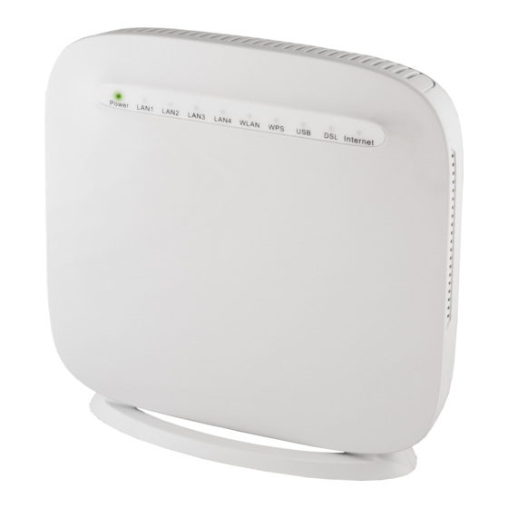
Device Installation The TW-EAV510 connects two separate physical interfaces, an xDSL (WAN) and an Ethernet (LAN) interface. Place the Router in a location where it can be connected to the various devices as well as to a power source. The Router should not be located where it will be exposed to moisture or excessive heat. -
Page 5: Network Connections
Network Connections Connect xDSL Line Use the xDSL cable included with the Router to connect it to a telephone wall socket or receptacle. Plug one end of the cable into the xDSL port (RJ-11 receptacle) on the rear panel of the Router and insert the other end into the RJ-11 wall socket. If you are using a low pass filter device, follow the instructions included with the device or given to you by your service provider. -
Page 6: Web-Based Configuration Utility
Web-based Configuration Utility Connect to the Router The default IP address for xDSL MODEM is: 192.168.0.254; The Subnet Mask is: 255.255.255.0. Users can configure xDSL MODEM through an Internet browser. xDSL MODEM can be used as gateway and DNS server; users need to set the computer’s TCP/IP protocol as follow: Set the computer IP address at same segment of xDSL MODEM, such as set the IP address of the network card to one of the “192.168.0.100”~... -
Page 7: Device Info
Device Info To access the Device Info window, click either the Device Info or Summary button in the Device Info directory. The following page opens:... -
Page 8: Summary
Summary To access the Router’s first Summary window, click the Summary button in the Device Info directory. This window displays the current status of your DSL connection, including the software version, LAN IP address, and DNS server address. To access the WAN Info window, click the WAN button in the Device Info directory. This window displays the current status of your WAN connection. -
Page 9: Statistics
Statistics The Statistics menu contains statistical information about the LAN, WAN service, and Optical. Select Statistics in the Device Info menu to open the Statistics submenu. The LAN window displays the statistics for the information received and transmitted over the LAN interface. - Page 10 To access the Device Info – xTM window, click the xTM button in the Device Info directory. This read-only window displays xTM info. xDSL To access the Device Info – XDSL window, click the xDSL button in the Device Info directory.
-
Page 12: Route
Route To access the Device Info – Route window, click the Route button in the Device Info directory. This read-only window displays routing info. To access the Device Info – ARP window, click the ARP button in the Device Info directory. This read-only window displays Address Resolution Protocol info. -
Page 13: Advanced Setup
Advanced Setup This chapter include the more advanced features used for network management and security as well as administrative tools to manage the Router, view status and other information used to examine performance and for troubleshooting. Layer2 Interface To access the DSL ATM Interface Configuration window, click the ATM Interface button in the Layer2 Interface directory. -
Page 14: Atm Interface
ATM Interface The ATM PVC Configuration window allows you to set up ATM PVC configuration. Enter Virtual Path Identifier, and Virtual Channel Identifier. The VPI and VCI values should be provided by your ISP. This window also allows you to select DSL Link Type, PPPoA 、 IPoA and EoA (EoA is for PPPoE, IPoE, and Bridge) Use the drop-down menu to select the desired Encapsulation Mode. - Page 15 VDSL2 (ptm) interface The VDSL2 (ptm) interface Configuration window enables you to add, delete, or modify up to one VDSL WAN Layer 2 interface connections. Click VDSL2 (ptm) Interface in the Layer2 Interface menu to open the VDSL(ptm) WAN Interface Configuration window VDSL WAN Configuration If you have selected to add or modify a VDSL interface connection, the VDSL WAN Configuration window opens.
- Page 16 ETH interface The ETH WAN Interface Configuration window enables you to add, delete, or modify up to one ETH WAN Layer 2 interface connections. Click ETH Interface in the Layer2 Interface menu to open the ETH WAN Interface Configuration window ETH WAN Configuration If you have selected to add or modify an ETH interface connection, the ETH WAN Configuration window opens...
-
Page 17: Wan Service
WAN Service To access the Wide Area Network (WAN) Service Setup window, click the WAN Service button in the Advanced Setup directory. This window is used to configure the WAN interface. You can add and delete WAN interface on this window. If you are setting up the WAN interface for the first time, click the Add button. - Page 18 WAN Service Configuration – PPPoE This window allows you to set the username and the password for your PPP connection. This information is obtained from your ISP. Additional settings on this window will also depend on your ISP. And you can input 2 IP on this page.
- Page 19 WAN Service Configuration – IPoE This window allows you to configure the WAN IP settings. This information is obtained from your ISP. Click the Next button to continue...
- Page 20 WAN Service Configuration – Bridging Click the Bridge radio button on this window. Click the Next button to continue.
-
Page 21: Lan
You can configure the LAN IP address to suit your preference. Many users will find it convenient to use the default settings together with DHCP service to manage the IP settings for their private network. The IP address of the Router is the base address used for DHCP. In order to use the Router for DHCP on your LAN, the IP address pool used for DHCP must be compatible with the IP address of the Router. -
Page 22: Ipv6 Autoconfig
IPv6 Autoconfig The IPv6 Autoconfig window enables you to configure the settings for the LAN interface with IPv6. Click IPv6 Autoconfig in the LAN submenu to open the IPv6 Autoconfig window; This window allows you to configure IPv6. When you are finished, click the Apply / Save button. -
Page 23: Ethernet Port
Ethernet Port To access the Ethernet Port window, click the Ethernet Port button in the Advanced Setup submenu. You can configure the Media Type of Ethernet port in the new page and it will show you the Link Status of each Ethernet port. When you are finished, click the Save/Apply button Virtual Servers Select Virtual Servers from the Advanced Setup menu to open the NAT submenu. -
Page 24: Port Triggering
Port Triggering Some applications such as games, video conferencing, remote access applications and others require that specific ports in the Router's firewall be opened for access by the applications. You can configure the port settings from this screen by selecting an existing application or creating your own (Custom application). -
Page 25: Dmz Host
DMZ Host Since some applications are not compatible with NAT, the Router supports use of a DMZ IP address for a single host on the LAN. This IP address is not protected by NAT and will therefore be visible to agents on the Internet with the right type of software. Keep in mind that any client PC in the DMZ will be exposed to various types of security risks. -
Page 26: Security
Security To access the Security window, click the Security button in the Advanced Setup directory. The Security button appears after configuring WAN interface in PPPoA, PPPoE, IPoE or IPoA. IP Filtering The IP Filtering button appears when configuring WAN interface in PPPoA, PPPoE, IPoE or IPoA. - Page 27 Now default policy is ACCEPT, it means all outgoing IP traffic from LAN is allowed, but some IP traffic can be blocked by setting up filters. If you are setting up the outgoing IP filtering, click the Add button. Enter the information in the section. Explanations of parameters are described below. Click the Apply / Save button to add the entry in the Active Outbound IP Filtering table.
-
Page 28: Mac Filter
Enter the information in the section. Explanations of parameters are described below. Click the Apply / Save button to add the entry in the Active Inbound IP Filtering table. MAC filter The MAC Filtering window enables you to control access to and from specific MAC addresses. Select MAC Filtering from the Security submenu to open the MAC Filtering Setup window;... -
Page 29: Parental Control
Parental Control Use this window to deny access to specified MAC address. Time Restriction If you are setting up the MAC address blocking, click the Add button. MAC address is a specially formatted text string (xx:xx:xx:xx:xx:xx) that uniquely identification of a device. This section will allow users to block devices with certain MAC addresses on the LAN. -
Page 30: Url Filter
URL Filter This window allows you to set up URL Filter on the Router. Choose URL List Type Exclude or Include first and click Add button. Enter the URL address and port number then click Apply / Save to add the entry to the URL filter. - Page 31 To access the 3G window, click the 3G button in the Advanced Setup directory. This window allows you to set up 3G on the Router. When you are finished, click on the Save/Apply button. If you want to add new 3G dongle, click driver add button, and the new page will show you how to configure a new 3G dongle.
-
Page 33: Quality Of Service
Quality of Service QoS or Quality of Service allows your Router to help prioritize the data packet flow in your Router and network. This is very important for time sensitive applications such as VoIP where it may help prevent dropped calls. Large amounts of non-critical data can be scaled so as not to affect these prioritized sensitive real-time programs. -
Page 34: Qos Classification
QoS Classification Choose Add or Remove to configure network traffic classes. Use this window to create a traffic class rule to classify the upstream traffic, assign a queue that defines the precedence and the interface, and optionally overwrite the IP header DSCP byte. -
Page 35: Routing
Routing To access the Routing windows, click the Routing button in the Advanced Setup directory. Default Gateway Default gateway interface list can have multiple WAN interfaces served as system default gateways but only one will be used according to the priority with the first being the highest and the last one the lowest priority if the WAN interface is connected. -
Page 36: Static Route
Static Route Click the Add button on the Routing – Static Route window to access the following window displayed on the next page. Enter the static routing information for an entry to the routing table. Click the Apply / Save button when you are finished. Policy Routing Click the Add button on the Policy Routing Setting window to access the following window displayed on the next page. -
Page 37: Dns
To activate RIP for the device, select the Enabled radio button for Global RIP Mode. To configure an individual interface, select the desired RIP version and operation, followed by placing a check in the 'Enabled' checkbox for the interface. Click the Save/Apply button to save the configuration, and to start or stop RIP based on the Global RIP mode selected. -
Page 38: Dynamic Dns
Dynamic DNS The Router supports Dynamic DNS (Dynamic Domain Name Service). The Dynamic DNS service allows a dynamic public IP address to be associated with a static host name in any of the many domains, allowing access to a specified host from various locations on the Internet. This is enabled to allow remote access to a host by clicking a hyperlinked URL in the form hostname.dyndns.org, Many ISPs assign public IP addresses using DHCP, and this can make it difficult to locate a specific host on the LAN using standard DNS. - Page 39 DDNS requires that an account be setup with one of the supported DDNS servers prior to engaging it on the Router. This function will not work without an accepted account with a DDNS server. Note...
-
Page 40: Dsl
The DSL window enables you to configure the DSL settings of the gateway. Select DSL from the Advanced Setup menu to open the DSL Settings window If you clicked Advanced Settings in the DSL Settings window, the DSL Advanced Settings window opens... -
Page 41: Upnp
If you clicked the Tone Selection button, the ADSL Tone Settings window opens Note: The ADSL tone settings should only be configured with the assistance of your ISP. UPNP To access the UPnP Configuration window, click the UPnP button in the Advanced Setup directory. -
Page 42: Dlna
DLNA Select DLNA from the Advanced Setup menu to open the DLNA window. This window allows you to config DLNA function. Click the Apply / Save button when you are finished. Storage service The Storage Service window displays Storage Device information from USB interface. Select from the menu to open the Storage Service window... -
Page 43: Interface Grouping
Interface Grouping Interface Group supports multiple ports to PVC and bridging groups. Each group will perform as an independent network. To support this feature, you must create mapping groups with appropriate LAN and WAN interfaces using the Add button. The Remove button will remove the grouping and add the ungrouped interfaces to the Default group. -
Page 44: Ip Tunnel
IP Tunnel Select IP Tunnel from the Advanced Setup menu to open the IP Tunnel submenu. IPv6inIPv4 Select from the submenu to open the IP Tunneling-6in4 Tunnel IPv6inIPv4 IP Tunnel Configuration window If you click Add, the detail of the IP Tunneling-6in4 Tunnel Configuration window will open IPv4inIPv6 Select from the... -
Page 45: Ipsec
IPSec To access the IPSec Tunnel Mode Connections window, click the IPSec button in the Advanced Setup directory. This window allows you to configure IPSec. Click Add New Connection to edit IPSec tunnel mode connections from this page This window allows you to advanced settings. -
Page 46: Power Management
Power Management The Power Management window enables you to control of Hardware to evaluate power consumption. Select from the menu to open the Power Management Power Management Advanced Setup window... -
Page 47: Multicast
Multicast To access the IGMP Configuration window, click the Multicast button in the Advanced Setup directory. Enter IGMP protocol configuration fields if you want modify default values shown below... -
Page 48: Wireless
Wireless Basic The Basic menu enables you to configure basic features of the wireless LAN interface. Select from the menu to open the basic submenu; Basic Wireless... -
Page 49: Security
Security This page allows you to configure security features of the wireless LAN interface. You may setup configuration manually or through WiFi Protected Setup(WPS) You can select to configure WEP encryption, Shared, 802.1x, WPA, and WPA2 authentication. -
Page 50: Mac Filter
MAC Filter This page can help you to allow or deny certain MAC addresses to pass through or block out. Click Add to see the following page. Enter MAC Address and click Apply / Save to add the MAC address to MAC filter. -
Page 51: Wireless Bridge
Wireless Bridge The Wireless Bridge menu enables you to configure wireless bridge features of the wireless LAN interface. Select from the menu to open the wireless bridge submenu Wireless Bridge Wireless Advanced This page allows you to configure advanced wireless LAN interface. Configuring these settings may increase the performance of your router but if you are not familiar with networking devices and protocols, this section should be left at its default settings. -
Page 52: Station Info
Station Info This page shows the authenticated wireless stations and their status. Click Refresh to update the information. -
Page 53: Diagnostics
Diagnostics Diagnostics Your modem is capable of testing your DSL connection with access to Diagnostics. This window is used to test connectivity of the Router. Fault Management Fault Management enables you to test the connectivity of the xDSL PTM mode. Note: Fault management should only be run with assistance from your ISP. -
Page 54: Management
Management The Management directory features an array of options designed to help you get the most out of your Router. Settings To access the Settings - Backup window, click the Settings button in the Management directory. This window allows you to backup your DSL Router configurations. Click the Backup Settings button to save your Router configurations to a file on your computer. -
Page 55: System Log
This window allows Restore DSL router settings to the factory defaults. Click the Restore DSL Settings button to restore DSL router settings to the factory defaults. System Log The System Log windows enable you view and configure the system log of this device. Select System Log in the Management menu to open the System Log window If you clicked View System Log in the System Log window, the System Log information window opens;... -
Page 56: Security Log
opens; Note: Configuring the system log should be done with assistance from your ISP. Security Log The System Log windows enable you view the security log of this device. Select Security Log in the Management menu to open the Security Log window; If you clicked View in the Security Log window, the Security Log information window opens;... -
Page 57: Tr069 Client
TR069 client The TR-069 Client window enables you to configure the ACS for this device Select TR-069 Client in the Management menu to open the TR-069 Client-Configuration window; Internet Time To access the Time settings window, click the Internet Time button in the Management directory. -
Page 58: Access Control
Access Control To access the Access Control windows, click the Access Control button in the Management directory. Passwords This window allows you to change the password on the Router. When you are finished, click the Save/Apply button. Services The Services window enables you to enable or disable services Select Services from the Access Control menu to open the Services window... - Page 59 IP Addresses The IP Address Access Control mode, if enabled, permits access to local management services from IP addresses contained in the Access Control List. If the Access Control mode is disabled, the system will not validate IP addresses for incoming packets. The services are the system applications listed in the Service Control List.
-
Page 60: Reboot
Input the IP Address and Subnet Mask which you want to configure, and then click Apply to enable this IP Address. Reboot To access this window, click the Reboot button in the Management directory. To save your settings and reboot the system, click the Reboot button. Tools This page will help you to diagnostic the status of your Network. -
Page 61: Troubleshooting
Troubleshooting How do I configure my TW-EAV510 Router without the CD-ROM? Connect your PC to the Router using an Ethernet cable. • Open a web browser and enter the address http://192.168.0.254 • The default username is ‘admin’ and the default password is ‘admin’. - Page 62 Note: There might be a potential security issue if you disable the setting of Firewall on your PC. Please remember to turn it back on once you have finished the whole installation procedure and can surf on Internet without any problem...
-
Page 63: Glossary
Glossary Numerics 10/100Base-T The most widely used standard for Ethernet over twisted pair or copper-based computer networking. Runs at 10 Mb/s, 100 Mb/s, and 1000 Mb/s (1 Gb/s) respectively. Auto-Configuration Server ADSL Asymmetric Digital Subscriber Line Application-Level Gateway Asynchronous Transfer Mode CHAP Challenge-Handshake Authentication Protocol Customer Premises Equipment... - Page 64 Ethernet A family of frame-based computer networking technologies for local area networks (LANs). Firewall An integrated collection of security measures designed to prevent unauthorized electronic access to a networked computer system. Gateway A network node equipped for interfacing with another network that uses different protocols. HDSL High-Rate Digital Subscriber Line HTML...
- Page 65 Network Address Translation Net mask The designated IP address routing prefix for a network of computers and devices. Network Interface Controller Network Time Protocol Operations, Administration, and Maintenance Password Authentication Protocol Ping A computer network tool used to test whether a particular host is reachable across an IP network. Point-to-Point Protocol PPPoE Point-to-Point Protocol over Ethernet...
- Page 66 User Datagram Protocol UPnP Universal Plug and Play Uniform Resource Locator Universal Serial Bus Virtual Circuit ID xDSL Very High Bit rate Digital Subscriber Line VLAN Virtual Local Area Network Virtual Path ID Wide Area Network...
Need help?
Do you have a question about the TW-EAV510 and is the answer not in the manual?
Questions and answers