Table of Contents
Advertisement
Quick Links
Download this manual
See also:
User Manual
Advertisement
Table of Contents

Subscribe to Our Youtube Channel
Related Manuals for ALLEN & HEATH GS-R24


Summary of Contents for ALLEN & HEATH GS-R24
- Page 1 Analogue Interface Module USER GUIDE Publication AP8348...
-
Page 3: Warranty
Limited One Year Manufacturers Warranty This product is warranted to be free from defects in materials or workmanship for period of one year from the date of purchase by the original owner. To ensure a high level of performance and reliability for which this equipment has been designed and manufactured, read this User Guide before operating. -
Page 4: Packed Items
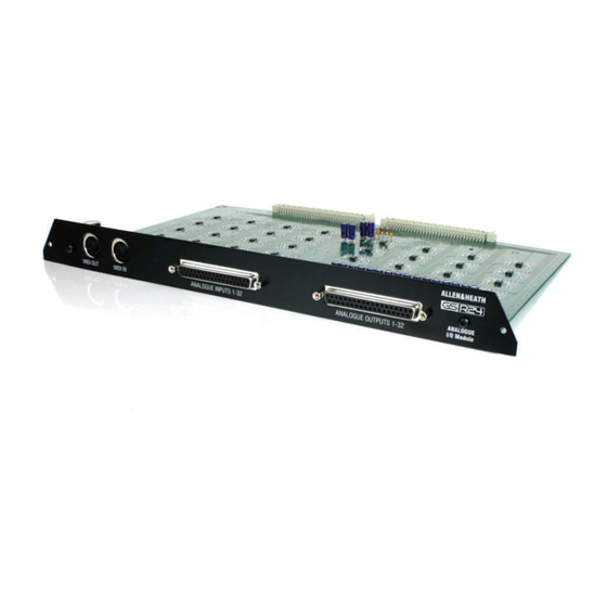
PACKED ITEMS Check that you have received the following: ALLEN&HEATH ANALOGUE MIDI OUT MIDI IN ANALOGUE INPUTS 1-32 ANALOGUE OUTPUTS 1-32 I/O Module GS-R24 ANALOGUE INTERFACE MODULE Also Packed in the box • Safety Instructions—English • Safety Instructions—French • Addendum note ROHS •... -
Page 5: Table Of Contents
CONTENTS Thank you for purchasing your Allen & Heath GS-R24 Analogue interface module. To ensure that you get the maximum benefit from the unit please spare a few minutes familiarizing yourself with the features and setup procedures outlined in this user guide. For further information please refer to the additional information available on our web site, or contact our technical support team. -
Page 6: Specifications
GS-R24 ANALOGUE MODULE SPECIFICATIONS General Specifications Number of audio channels Output Number of audio channels Input Nominal Signal Level 0dBu Analogue signal connector type 37 pin D sub MIDI Input 5pin DIN MIDI Output 5pin DIN Headroom Digital domain headroom (nominal to 0dBFS) 21dB Channel Mapping to Interface Console Channels... -
Page 7: Fitting Instructions
MODULE FITTING INSTRUCTIONS Beware of ESD! Observe anti-static handling precautions—avoid touching the electronic devices on the circuit board, ensure any static build up is discharged to earth before handling the module. This can be achieved by ensuring the console is connected to the psu and the psu is plugged in to a mains outlet but switched OFF, then touching a metal part of the console panel such as a screw head. -
Page 8: Analogue In/Out Connector Pin Numbers
37 PIN D TYPE CONNECTOR PINNING Analogue Input & Output 37 way D connector pin ident. View of rear connector. Observe pin numbering of connector to be wired. Pin assignment (Input or Output connectors) Connection guidelines & notes PIN No. Designation CHASSIS The type of connection cable you will need depends on... -
Page 9: Module Panel Features
MODULE PANEL FEATURES ALLEN&HEATH ANALOGUE MIDI OUT MIDI IN ANALOGUE INPUTS 1-32 ANALOGUE OUTPUTS 1-32 I/O Module MIDI Input & Output Standard 5 pin DIN MIDI connectors. The MIDI OUT carries the MIDI data generated by the MIDI controllers and switches on the GS-R24. The MIDI IN is the MIDI data required to illuminate LEDs and provide mov- ing fader information to the console. -
Page 10: Product Support
PRODUCT SUPPORT www.allen-heath.com Investigate ALLEN & HEATH’s other ranges at Large Live Sound mixers — iLive digital, and GL Series Small Format Live Sound mixers — ZED, MixWizards and PA Series DJ products — Xone Series Sound Management Series — iDR Series Registering your product Thank you for buying the Allen &...
Need help?
Do you have a question about the GS-R24 and is the answer not in the manual?
Questions and answers