
Subscribe to Our Youtube Channel
Related Manuals for Fagor AD – 21 W


Summary of Contents for Fagor AD – 21 W
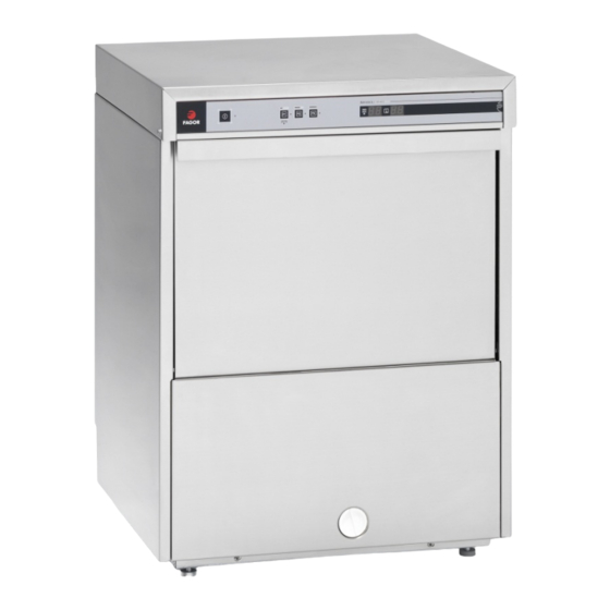
- Page 1 SERVICE MANUAL ********** 2013 UNDERCOUNTER GLASSWASHER UNDERCOUNTER GLASSWASHER Models: AD – 21 W ...
-
Page 2: Table Of Contents
WATER INSTALLATION ............................6 REQUESTED QUALITY OF THE WATER ......................7 WATER DRAINAGE INSTALLATION ........................7 ELECTRICAL CONNECTION ...........................8 INSTALLATION CHECKLIST ............................9 OPERATION ................................9 TURNING THE MACHINE ON ......................... 10 PREPARING THE MACHINE ........................... 10 WASHING .............................. 10 COOL RINSE ............................... 11 DRAINING AND CLEANING .......................... 11 DETERGENT CONTROL ............................ 12 PREPARING THE WARE............................ 13 DELIMING .............................. 13 TROUBLESHOOTING ............................ 14 DIAGNOSTICS .............................. 17 ELECTRICAL DIAGRAM ............................ 18 WIRING SCHEMATIC ............................ 19 RECOMMENDED SPARE PARTS ......................... 20 LIMITED WARRANTY ............................ 21 For Customer Service: Call 1‐866‐GO FAGOR – www.fagorcommercial.com | P. II... -
Page 3: Specifications
Motor (hp): 1/3 HP Width: 20” / 508 mm Depth: 24 1/2” / 622 mm Temperatures Height: 34 1/2” / 876 mm Wash: 150ºF / 66ºC Max clearance for dishware: 10 ½” / 267mm Rinse: 180ºF / 82ºC Rack: 16” x 16” / 400mm x 400mm Shipping weight: 105 lbs. / 47.5 kg Shipping volume (cu. ft.): 10 TECHNICAL SPECIFICATIONS Total Power Consumption Boiler Power Consumption Volts Amps Power (KW) Volts Amps Power (KW) 208/60/1 13.1 2.7 208/60/1 12 2.5 220/60/1 14.9 3.2 220/60/1 12.7 2.8 240/60/1 15.0 3.6 240/60/1 13.75 3.3 Pump Power Consumption Volts Amps Power (KW) 208/60/1 1.10 0.5 220/60/1 1.18 0.6 240/60/1 1.25 0.7 For Customer Service: Call 1‐866‐GO FAGOR – www.fagorcommercial.com | P. 3... -
Page 4: Installation
INSTALLATION VISUAL INSPECTION Before installing the unit, check the package and machine for damage. All machines have been tested, inspected and packed at the factory and is expected to arrive to you in new, undamaged condition. Visually inspect the exterior of the package. Any damage should be noted and reported to the delivering carrier immediately. If damaged, open and inspect the contents with the carrier. In the event that the exterior is not damaged, yet upon opening there is concealed damage to the equipment, please notify the carrier. Notification should be made verbally as well as in written form. Request an inspection by the shipping company of the damaged equipment. Also, contact the dealer through which you purchased the unit. INSTALLATION DIAGRAMS A = Water inlet D = Drain hose E = Electrical Cable R = Terminal Block For Customer Service: Call 1‐866‐GO FAGOR – www.fagorcommercial.com | P. 4... -
Page 5: Positioning
Any transformations or changes made on the machines during installation should be reflected on the data plate or using a label as below: Total load at indicated POSITIONING Leveling and adjusting the height of the appliance is done by turning the leveling stands to the desire height. Ensure that the unit is level before making any connections (Fig. 2). AD 21 W Fig.2 For Customer Service: Call 1‐866‐GO FAGOR – www.fagorcommercial.com | P. 5... -
Page 6: Water Installation
CAUTION: Do not confuse static pressure with flow pressure. Static pressure is the line pressure in a “no flow” condition (all valves and services are closed). Flow pressure is the pressure in the fill line when the solenoid valve is opened during the cycle THE DISPLAY OF THE PRESSURE GAUGE SHALL BE CLEARLY VISIBLE OF THE OPERATOR OF THE MACHINE. THE GAUGE SHALL HAVE INCREMENTS OF 1 psi (7 kpa) OR SMALLER AND SHALL BE ACCURATE TO ±2 psi (±14 kpa) IN THE 20 psi (103‐172 kpa) RANGES. IF THE GAUGE IS LOCATED UPSTREAM OF THE CONTROL VALVE, IT SHALL BE MOUNTED IN AN ACCESSIBLE VALVE WITH A ¼ IN IRON PIPE SIZE CONNECTION. If the water pressure is less than 20 psi (1.4 kg/cm ), installation of a water pump is required as shown in Fig. 4. In areas where the pressure fluctuates or is greater than the recommended pressure, it is suggested that a water pressure regulator be installed. S = Stop cock F = Filter H = Hose E = Electro valve B = Electro pump M = Manometer R = ¾” Copper For Customer Service: Call 1‐866‐GO FAGOR – www.fagorcommercial.com | P. 6... -
Page 7: Requested Quality Of The Water
Use only the supplied hoses (3/4” Female hose connector) at the water connections. Failure to do so may result in damage to the solenoid valve threads and leaking. Tighten by hand. Connect the bent side of the hose to the machine. Adaptor supplied for ¾” female garden hose connection. FOR HARD WATER SUPPLIES WITH A HARDNESS OF OVER 2 GRAINS OR 10ºF AND PH BEYOND THE RANGE OF 7.0 – 8.5, A WATER CONDITIONER MUST BE INSTALLED. Slowly turn on the water supply to the machine after the incoming fill line and the drain line have been installed. Check for any leaks and repair as required. All leaks must be repaired prior to placing the machine in operation. WATER DRAINAGE INSTALLATION Attach the drain hose as shown in Fig. 5. It is recommended to affix a siphon pipe to prevent odors. All piping from the machine to the drain must be a minimum 1‐1/2” I.P.S. There should also be an air gap between the machine drain line and the drain. For natural overflow efficiency use floor drain. D = Drain hose C = Drain collector A = Air Gap F = Scrap Basket Fig. 5 For Customer Service: Call 1‐866‐GO FAGOR – www.fagorcommercial.com | P. 7... -
Page 8: Electrical Connection
BLUE CAP - Red Wire Neutral BLUE CAP – Red Wire Fig. 6 WARNING: Electrical Shock Hazard It is the personal responsibility and obligation of the customer to contact a qualified electrician to assure that the electrical installation is adequate and is in conformance with the National Electrical Code, ANSI / NFPA 70 – latest edition and all local codes and ordinance. For Customer Service: Call 1‐866‐GO FAGOR – www.fagorcommercial.com | P. 8... -
Page 9: Installation Checklist
Is the incoming water supply at 20 ‐ 25 psi? Verify water hose, drain hose and chemical hoses are not kinked? Is the hot water supply at the optimum temperature (140ºF)? If not, list water temperature _______ °F Is the water hardness ≤2.0gpg/34.2ppm and PH level 7 ‐ 8.5ph? Has the drain plumbing been installed according to the instructions in this manual? Height of the drain hose ______ Air gap size _______ Was the drain installed to a garbage disposal? If yes, has been installed a back flow safety in case the garbage disposal fail? ____ Damages to a drain pump due to a failure of a garbage disposal will not be covered under warranty Is the overflow tube with the O‐ring fitted in its position inside the tank Is the detergent for commercial dishwashers? Have you adjusted the amount of detergent / rinse going to the machine? ____ Adjustments on detergent/rinse pump are not cover under warranty. Please refer to page 18 for instructions. In order to validate your warranty this checklist must be return to Fagor along with the product registration card. MODEL NO.__________________________ Registration can be completed by mail, phone, and fax or on the SERIAL NO.___________________________ website www.fagorcommercial.com INSTALLATION DATE ___________________ Fax: 3057790173 SERVICE REP. NAME ___________________ 13105 NW 47 Ave. Opa Locka, FL 33054 servicerequest@fagorcommercial.com PHONE Nº ___________________________ For Customer Service: Call 1‐866‐GO FAGOR – www.fagorcommercial.com | P. 9... -
Page 10: Turning The Machine On
6 4 Fig. 7 TURNING THE MACHINE ON Press and hold the power button (1) for five seconds. LED # 2 will lit up and the machine will start filling up with water. PREPARING THE MACHINE After the machine has filled it will start heating up the rinse tank and the wash tank. The machine is ready to wash when the thermometer (9) indicates 180º F (83˚C) and the thermometer (10) 160º F (71˚C). It is the user’s responsibility to wait until the minimum temperatures are displayed before putting the machine to wash. WASHING NOTE: All models are fitted with Thermo‐stop. The temperature of the incoming water should be higher than 120°F/ 50 ºC. (Ideal temp. 140°F/60 ºC) If it is lower, the machine's capacity may be affected and you may have extended cycles. There are 3 washing cycles for models described before: P1 (3), P2 (5) and P3 (7) of 60, 90 and 180 seconds respectively. (Fig.7). LED’s numbers 4, 6 and 8 indicate that the machine is working; depending on selected programme, one or other led will switch on. If you start your dishwasher prior to your booster heater (9) reaching a minimum of 180º F (83ºC), YOU WILL HAVE AN EXTENDED WASH CYCLE! For Customer Service: Call 1‐866‐GO FAGOR – www.fagorcommercial.com | P. 10... -
Page 11: Cool Rinse
4 Fig. 7 Draining the Machine Open the door and remove the Front Right S/S Filter, leave door open. (Fig. 8) Remove the overflow tube by inserting a finger into the top of the tube. (Fig. 9) DO NOT REMOVE SCRAP BASKET! DO NOT LOOSE O’RING FROM OVERFLOW TUBE! Press and hold the button P1 (3) for 5 seconds (Fig. 9). The led number 4 will illuminate during operation Wait until the led (3) turns off. (3 minutes 20 seconds) Take out scrap basket for cleaning by twisting to the left. (Fig. 10) Replace scrap basket, lock into position by twisting to the right and replace overflow tube with O‐ring. Replace S/S filter back into position. (Fig. 8) Press power switch (1) to turn unit OFF For Customer Service: Call 1‐866‐GO FAGOR – www.fagorcommercial.com | P. 11... -
Page 12: Detergent Control
To avoid the risk of damage from oxidization or corrosion from chemicals, keep all steel surfaces clean and dry. It is advisable to change the tank water, by new filling, at least every 40‐50 washes or twice a day. DETERGENT CONTROL Use ONLY Commercial Grade, High Temperature, Low Suds Liquid Detergent. Fagor doesn’t recommend any specific brand name of chemicals. Contact your local chemical distributor for questions concerning your chemical needs. All machines come equipped with an internal Detergent and Rinse dispenser. Take the tube located in the back or your machine marked “Detergent” and place inside detergent container. Take the tube with a blue stripe mark and place inside rinse container. Tubes are clear to provide you a visible means that chemicals are being dispensed. If desired you can control the amount of Chemical being dispensed by opening the bottom front panel of the machine. Locate the detergent dispenser (Fig. 9) and regulate according to the flow chart (Fig. 9a). For the Rinse, turn the button counterclockwise to get more rinse aide and clockwise for less. Verify all connections to the dispenser are hand tighten to prevent any leaks. Control and maintain the level of detergent and rinse aid of the tanks. Keep chemical tubing and filters submerged. DETERGENT PUMP Fig. 9 DETERGENT ADJUSTMENT Gal./h. 220º Oº 1 0 2 0.06 ... -
Page 13: Preparing The Ware
Warning! If you require the installation of an NON FAGOR Detergent and Rinse pump, a form MUST be fill out prior to installation by your installer. Failure to do so will void your Warranty. This form can be located inside your dishwasher. If lost, please contact Fagor to get a copy. Note: The detergent pump and rinse dispensing pump will only work during the process of fill and rinse. PREPARING THE WARE Pre‐scrap and rinse all racks prior to placing them in the dishwasher to remove large food particles (pre‐ scrap) from the ware. Wash glassware first Put trays in the baskets, making sure is in its separate rack (Fig.12). Put plates in the baskets, making sure each is in its separate rack (Fig. 11). Put glasses in upside down. Put cutlery in the cutlery baskets handles down. Mix spoons with knives and forks. (Fig. 10) Put the special cutlery baskets in the base baskets. Fig. 10 Fig. 11 ... -
Page 14: Troubleshooting
Verify circuit board fuse is If connected and still not working, replace Adhesive Trim. Rinsing temperature gauge Wait until sanitized rinsing temperature reached a min.of is lower than 180ºF. 180ºF. Check out your incoming water temperature. Recommended incoming water temperature is 140°F For Customer Service: Call 1‐866‐GO FAGOR – www.fagorcommercial.com | P. 14... - Page 15 TEMPERATURE OF 180°F closes when receiving voltage. If not, replace heater relay (Cc). Faulty Boiler element (Rc) Ohm out element check for continuity; if open, replace heater (Rc). For Customer Service: Call 1‐866‐GO FAGOR – www.fagorcommercial.com | P. 15...
- Page 16 Make sure that the rinse agent chemical lines are primed and free of kinks. Rinse agent not being Detergent tubes not Verify detergent tubes are secured inside container dispensed placed properly inside Adjust chemicals to proper levels container/improper adjustment For Customer Service: Call 1‐866‐GO FAGOR – www.fagorcommercial.com | P. 16...
-
Page 17: Diagnostics
DIAGNOSTICS . ON/OFF LED FLASHING: Errors or Faults are notified by flashes of the ON/OFF LED. The flashes stay on for half second, followed by 2 seconds off. On On Off On On Off Example of a 2 flashes ERROR ( Tank Water Fill Error) 1 Flash ( OPEN DOOR): This is indicated by a one flash and a pause. This continues as long as the door is open and the selected cycle is unfinished. 2 Flashes ( TANK FILL ERROR): This is indicated by a two flashes and a pause. This continues while the water in the tank does not reach the correct level in the specified time. 3 Flashes ( TANK DRAINAGE ERROR): This is indicated by a three flashes and a pause. This continues while the drainage pump does not drain the water in the tank to the correct level in the specified time. 4 Flashes ( BOILER HEATING ERROR): This is indicated by a four flashes and a pause. This continues while the water in the boiler does not reach the correct temperature in the specified time. 5 Flashes ( TANK HEATING ERROR): This is indicated by a five flashes and a pause. This continues while the water in the tank does not reach the correct temperature in the specified time. TEMPERATURE PROBE ERROR: The display may show different alarms for the temperature probes. The alarm is shown on the corresponding display ( boiler temperature display or tank temperature display). ... -
Page 18: Electrical Diagram
ELECTRICAL DIAGRAM For Customer Service: Call 1‐866‐GO FAGOR – www.fagorcommercial.com | P. 18... -
Page 19: Wiring Schematic
WIRING SCHEMATIC For Customer Service: Call 1‐866‐GO FAGOR – www.fagorcommercial.com | P. 19... -
Page 20: Recommended Spare Parts
RECOMMENDED SPARE PARTS Part number Description P255001 Water fill valve (dual) R223005 Tank heating element 2000 W. Z203009 Door switch Z203062 Door relay Z268004 Temperature Probe Z213007 Contactor Z203062 RELE 230V. 16A 50‐60 HZ Z393005 Boiler thermostat Z400709 Washing nozzle Z400711 Washing nozzle bracket Z401001 Pump motor 60Hz. Z421711 Boiler heating element 2800W. Z433011 Pressure switch Z393005 Tank thermostat Z223501 Drain pump V817100 6 MF Capacitor Z231106 AntiReturn Valve 12045206 Rinse Pump ... -
Page 21: Limited Warranty
Warranty Coverage: If there is a defect in material or factory workmanship covered by this Warranty reported to Fagor during the period the applicable Warranty is in force and effect, Fagor will repair or replace, at Fagor’s option, that part of the Equipment that has become defective. Fagor will cover labor cost within one year from the Warranty Commencement date or 15 months from shipment date, whichever occurs first with the exception of the Glasswasher models, which will be 90 days labor and one year parts warranty. - Page 22 Fagor Commercial, Inc. 13105 NW 47 Ave. Miami, Fl. 33054 Tel: (305) 779 0170 Fax: (305) 779 0173 1‐866‐GO‐FAGOR www.fagorcommercial.com For Customer Service: Call 1‐866‐GO FAGOR – www.fagorcommercial.com | P. 22...
Need help?
Do you have a question about the AD – 21 W and is the answer not in the manual?
Questions and answers