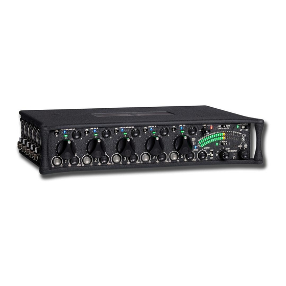
Sound Devices 552 User Manual And Technical Information
Five-channel portable production mixer with integrated recorder
Hide thumbs
Also See for 552:
- User manual and technical information (60 pages) ,
- User manual and technical information (56 pages) ,
- Quick start manual (57 pages)
Table of Contents
Advertisement
Quick Links
Advertisement
Table of Contents

Related Manuals for Sound Devices 552


Summary of Contents for Sound Devices 552
- Page 1 Five-Channel Portable Production Mixer with Integrated Recorder User Guide and Technical Information Sound Devices, LLC 300 Wengel Drive • Reedsburg, WI • USA +1 (608) 524-0625 • fax: +1 (608) 524-0655 Toll-Free: (800) 505-0625 www.sounddevices.com support@sounddevices.com...
-
Page 3: Table Of Contents
552 User Guide and Technical Information Table of Contents Quick Start Guide ..... . .3 Metering ......27 Meter Ballistics Front Panel Descriptions . - Page 4 LLC. SOUND DEVICES is not responsible for any use of this information. SOUND DEVICES, LLC shall not be liable to the purchaser of this product or third parties for damages, losses, costs, or expenses incurred by purchaser or third parties as a result of: accident, misuse, or abuse of this product or unauthorized modifi cations, repairs, or alterations to this product, or failure to strictly comply with SOUND DEVICES, LLC’s operating and installation instructions.
-
Page 5: Quick Start Guide
552 User Guide and Technical Information Quick Start Guide This Quick Start Guide provides a brief overview for fi rst use of the 552. Connect power. For internal powering from AA batteries, unscrew the battery cap (counter-clock- wise), insert four AA batteries (not included) positive (+) side fi rst into the battery tube. - Page 6 Apply Phantom Power to an input requiring Phantom Power. The 552 supplies 48 V to inputs set to receive phantom power (PH). Phantom Pow- er can be set to 12 V in the Setup Menu. To apply phantom power, hold an input’s PFL switch, then slide the SLATE MIC/TONE switch to the right.
- Page 7 552 User Guide and Technical Information Set Input Faders in use to unity gain (0 dB or 12 o’clock). Faders not used should be set to off (full counter-clockwise position). Set Input Trim Levels. Push to release the recessed Trim (gain) Control. Turn the Trim Control clockwise to raise the level of the input.
- Page 8 Connect the next device in the signal chain’s output to either the RTN A or RTN B input of the 552. This will allow signal from that device to be monitored in the 552. Features and specifications are subject to change. Visit www.sounddevices.com for the latest documentation.
- Page 9 552 Right Panel Monitor return audio. Slide the RTN A/RTN B switch left or right to hear return audio in the 552 head- phones. For momentary action, hold the RTN A/RTN B for one second or longer. Adjust the return level by turning the Headphone Controller while return monitor- ing is active.
- Page 10 552 User Guide and Technical Information Controlling the Integrated Digital Recorder. The Recorder Controller is used to Record, Stop, Playback, Rewind, Fast Forward, and navigate through recorded fi les. Push up to begin recording. Push left to load the previous fi le.
- Page 11 552 User Guide and Technical Information 1. Press and hold the Battery Check Button. 2. Press in on the Headphone Controller. Flashing LEDs indicate the selected Setup Menu Function or option. Left Meter LEDs indicate Setup Menu Functions. Right Meter LEDs indicates the Turn to navigate through the Setup active option for the select Function.
-
Page 12: Front Panel Descriptions
552 User Guide and Technical Information Front Panel Descriptions All 552 settings are accessed and controlled from the Front Panel. This allows the unit to be placed in a production bag along while having complete control of the unit. 20 21 22... - Page 13 Slide Slate Mic/Tone switch right to acti- the RTN B TA3 connector. Time code is vate the Tone Oscillator. Tone will latch stamped to fi les generated by the 552. if held for 2 seconds or longer, slide See Time Code.
- Page 14 552 User Guide and Technical Information Front Panel Descriptions cont. 20 21 22 Power Switch RTN A/B Switch Three-position switch, selects between Two-position momentary switch. Slide internal battery power or external DC left for RTN A, slide right for RTN B.
-
Page 15: Rear Panel Descriptions
552 User Guide and Technical Information Rear Panel Descriptions SD Slot Remove the protective rubber cover to access the SD (Secure Digital) memory card slot. Insert the SD/SDHC card into the slot until it sits securely in the slot. The card should glide smoothly into the slot. -
Page 16: Right Panel Connectors And Controls
IFB transmitters pin-2 = Left, pin-3 = Right. or transcription recorders. Tip = Hot, Link I/O Sleeve = Ground. Used to link MixPre, 302, 442, and 552 Tape Out mixers. See Mixer Linking. Unbalanced stereo outputs on 3.5 mm Headphone Outputs female connector. -
Page 17: Top And Bottom Panels
552 User Guide and Technical Information Top and Bottom Panels Top and Bottom Panels Product Badge Made of molded carbon fi ber, this highly The product badge on the bottom panel specialized composite has nearly identi- can be covered with a customized iden- cal strength-to-weight properties as tity tag. -
Page 18: Input Setup And Control
Mic or Line indicates the general input level for each input channel. Taking into account all gain stages, the 552 has 93 dB of available gain from Mic input to Line output. When inputs are set to the LINE position, the input sensitivity is reduced by 40 dB. -
Page 19: Gain - Trim And Fader Relationship
Make certain to disable phantom power with Line-level output devices susceptible to damage from DC. The 552 can provide up to 10 mA to each input at 48 V, suffi cient for the most power-hungry con- denser microphones. Many phantom powered microphones do not require 48 V and can be properly powered with 12 V. -
Page 20: Input Faders
When possible, attempt to equalize at the sound source with microphone selection, placement, windscreens, and onboard microphone fi ltering. Many microphones have on-board high pass fi lters. Use the high-pass fi lters on the 552 in conjunction with the microphone’s fi lter to increase the fi lter’s slope. -
Page 21: Input Limiters
Sound Devices recommends that the limiters be active at all times. The Input Limiter does not alter signals below the threshold. When Input Channels are linked as a stereo pairs, the Input Limiters are also linked and perform the same gain reduction equally across the channels. -
Page 22: Stereo Pair Linking
MS pair the odd input’s Link and MS LEDs will illuminate blue. Output Setup and Control The 552 has two master analog outputs with numerous output connections; this output fl exibility is essential for complex, multi-camera productions. Because each input can be continuously panned from left to right, the outputs are used as either two separate mono buses or as a single, stereo bus. -
Page 23: Master Outputs
The Hirose 10-Pin also includes an unbalanced stereo Return A input for headphone monitoring. The Sound Devices XL-10 Breakout Cable is an available accessory that provides easy access to the balanced outputs and stereo RTN A connection of the 10-pin Hirose connector. -
Page 24: Mono Mic Outputs
552 User Guide and Technical Information Mono Mic Outputs The Mono Mic Output is a sum of the left and right output channels. The 3.5 mm female connector outputs a mono, mic-level signal intended for connection with portable transcription recorders and wireless IFB transmitters. -
Page 25: Output Limiter
Sound fi les recorded by the 552 are placed within a daily folder that is automatically generated when the mixer is powered on. Each audio fi le recorded by the 552 has a unique fi le name based on date and time information in 24-hour format. -
Page 26: Recording Media
The SD slot is located on the 552 Rear Panel. It is protected by a rubber cover. Gently pry the protec- tive rubber cover from left to right to expose the SD Slot. Insert the SD card into the slot. The card should glide smoothly into the slot. -
Page 27: Recorder Controller
LED fl ashes yellow. The LED will be off when media is attached and ready. When the 552 is actively recording the LED illuminates solid red. In the event that a record com- mand is given and the media is not ready, the LED fl ashes red. Media writing or reading activity is indicated by a solid yellow LED. -
Page 28: File Format
Files are sample-continuous and can seamlessly be joined in audio editing software. Bit Depth When recording WAV fi les, the 552 records either 16 or 24 bit fi les. 24-bit recording provides greater dynamic range and addition headroom for signal peaks versus 16-bit recordings. Sound Devices recommends 24-bit recording for all critical production. -
Page 29: Metering
Playback After a fi le has been recorded, the 552 can playback the fi le. Playback audio is sent to the headphone monitor. When in playback mode, the recorded program overrides the headphone monitor selection. The last fi le recorded is always the fi le that is immediately available for playback. -
Page 30: Meter Ballistics
In VU mode, the front panel meter labeling is in volume units. VU meters are always referenced to an actual signal level in dBu, the 552 VU meter is referenced with 0 VU corresponding to 0 dBu at the Line-Level outputs. If needed, the reference level can be changed in the Setup Menu to +4 or +8 dBu. -
Page 31: Headphone Peak Led
Recorder Source - audio program sent to the recorder, this is identical to AES A routing. . Voice Navigation The 552 features a Synthetic Voice for Enhanced Navigation, or SVEN. SVEN provides spoken word feedback when Setup Menu features are adjusted. He is designed to simplify control and provide important information to the user. -
Page 32: Headphone Source Selection
552 User Guide and Technical Information Function Description Remaining Record Time Press and hold the Battery Check button to announced remaining record time available on the inserted SD card. Not available while recording. Time Continue to hold the Battery Check button after Remaining Record Time announcement to hear the current time and date. -
Page 33: Powering
See Time Code for additional information. Return Loopback During typical operation the 552’s Left and Right output buses are sent to both the Tape outputs and the Mono Mic output. When set, Return Loopback allows Return A and/or Return B to be directly routed to the Tape and Mono Mic outputs. -
Page 34: External Powering
External Powering The 552 can be powered from any DC voltage from 10 to 18 VDC. Pin-4 of the locking, Hirose con- nector is positive (+) and pin-1 is negative (–). The external DC supply is fully isolated (fl oating) from the rest of the mixer for easy and safe interconnection with other external audio gear. -
Page 35: Tone Oscillator
Tone Oscillator Tone is used to set gain structure between the 552 and the next device in the signal path. The tone oscillator uses the right position of the slide switch. Slide right to activate, hold for two seconds to latch on. - Page 36 Slate Only Active Slate Mic signal only, sent to the right headphone monitor. Slate + Left Program 552 Left Program Mono sent to both monitors and active Slate Mic Signal sent to the right headphone monitor. Slate + Channel 1 Post-Fade Channel 1 Post-Fader sent to both monitors and active Slate Mic Signal sent to the right headphone monitor.
-
Page 37: Time Of Day/Date Clock
To Link two 552s together: Connect the Link I/O of 552 A to the Link I/O of 552 B using a TA5F to TA5F cable (Sound Devices XL- TA55 optional accessory). This will send the stereo mix of each 552 directly to the stereo output bus of both 552s. -
Page 38: Linking To A 302 Or 442
To link a Sound Devices 302 or 442 to a 552: Connect the Link I/O of the 552 to the Tape Out/Mix Out of a 302 or 442 using a Sound Devices XL- TA35 cable. This sends the stereo mix of both mixers directly to the stereo output bus of the 552. -
Page 39: Accessing The Setup Menu
User and Factory Settings The 552 can save and recall a User Setup File. To save a User Setup File, hold Input 1’s PFL then press and hold the Stop button for one second or longer. The Setup File is named SDMIX552.SUP and is placed in the SOUNDDEV folder on the SD card. -
Page 40: Setup Menu Chart
552 User Guide and Technical Information Setup Menu Chart The chart below shows the Setup Menu number, Function name, a description of the control, options available within that menu, and the factory default setting. Factory Default settings are always the fi... - Page 41 • 48 Volts (-30) 48 Volts applied to all inputs. When 12 V is selected • 12 Volts (-24) the overall power consumption of the 552 • 48 Volts Line (-22) is lowered. Line options allow phantom • 12 Volts Line (-20) to be applied to both Mic- and Line- Level inputs.
-
Page 42: Front Panel Button Shortcuts
552 User Guide and Technical Information Front Panel Button Shortcuts To speed navigation the 552 has numerous navigation “shortcuts”. For combinations, press and hold down the fi rst identifi ed key then press the next identifi ed key(s). Function Key Sequence... -
Page 43: Connector Pin Assignments
Tape Output 2 – Left Signal 3 – Right Signal 5-Pin 1 – HP Used to connect to MixPre, 302, 442, or 552 Field Mixers. Mixer Link I/O 2 – HP 3 – Mix 4 – Mix 5 – Link detection 3.5 mm... -
Page 44: Specifi Cations
XLR Line: Transformer-balanced for use with <2k ohm outputs RTN A,B (3.5 mm/TA3/10-pin): Unbalanced stereo for use with <2k ohm outputs Link I/O: Unbalanced stereo for use with 552 Link I/O or MixPre, 302, and 442 Mix Out/ Tape Out, 1.8k ohm output... - Page 45 552 User Guide and Technical Information Output Impedance XLR: 85 ohms at Line setting, 3.2k ohms at -10 setting, 150 ohms at Mic setting (ohms actual) 10-Pin: 85 ohms at Line setting, 3.2k ohms at -10 setting, 150 ohms at Mic setting...
-
Page 46: Accessories
2.0 kg, (4 lbs 6 oz.) without AA batteries Accessories Several high-value accessories are available for the 552, including production cases, cables, and power accessories. For a full list of Sound Devices products and accessories, visit our web site www.sounddevices.com/products. Optional 552 Related Accessories... -
Page 47: Wave Agent
NP-type battery cup with 24-inch cable terminated in Hirose 4-pin locking DC connector (HR10-7P-4P) at equipment end. XL-TA25 TA5F to 3.5 mm TRS, 12-inch, used to connect 552 TA5M Link I/O to the MixPre or 442 Tape Out/Mix Out 3.5 mm jack for mixer linking. XL-TA35 TA5F to TA3F, 12-inch, used to connect 552 TA5M Link I/O to 302 or 442 Tape Out/Mix Out TA3M connector for mixer linking. -
Page 48: Ce Declaration Of Conformity
552 - Printed in U.S.A.
Need help?
Do you have a question about the 552 and is the answer not in the manual?
Questions and answers