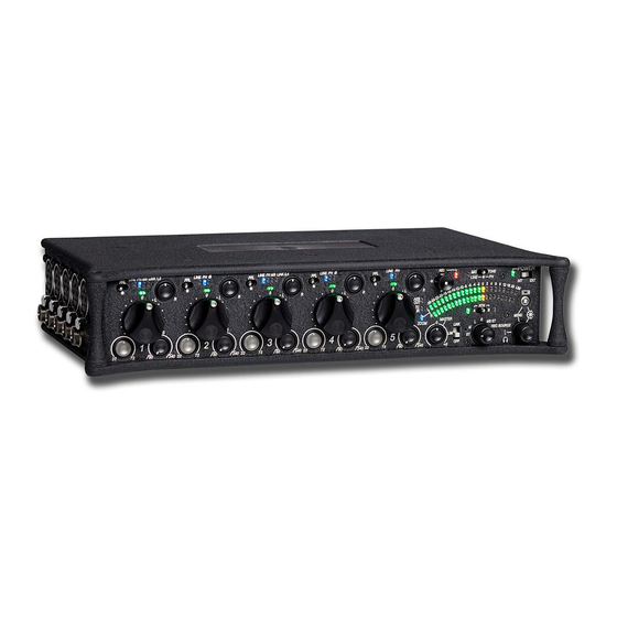
Sound Devices 552 Quick Start Manual
5 channel mixer/ 2 track recorder
Hide thumbs
Also See for 552:
- User manual and technical information (60 pages) ,
- User manual and technical information (56 pages) ,
- User manual and technical information (48 pages)
Table of Contents
Advertisement
Quick Links
Advertisement
Table of Contents

Related Manuals for Sound Devices 552


Summary of Contents for Sound Devices 552
- Page 1 Sound Devices 552 - 5 channel mixer – 2 track recorder...
- Page 2 Quick StartGuide This Quick Start Guide provides a brief overview for first use of the 552. Connect power. For internal powering from AA batteries, unscrew the battery cap (counter-clock- wise), insert four AA batteries (not included) positive (+) side first into the battery tube.
- Page 3 2) Slide the SLATE MIC/TONE switch left. Apply Phantom Power to an input. The 552 supplies 48 V to inputs set to receive phantom power (PH). Phantom pow- er can be set to 12 V in the Setup Menu. To apply phantom power, hold an input’s PFL switch, then slide the SLATE MIC/TONE switch to the right.
- Page 4 Set Input Faders in use to unity gain (0 dB or 1 2 o’clock). Faders not used should be set to off (full counter-clockwise position). Set Input Trim Levels. Push to release the recessed Trim (gain) Control. Turn the Trim Control clockwise to raise the level of the input.
- Page 5 Output Meter LEDs. The internal AA battery level is displayed on the left meter and external DC voltage level is displayed on the right meter. Connect the 552 analog outputs to the next device in the signal chain (audio recorder, wireless transmitter, or camera).
- Page 6 Push down to playback the last recorded file or loaded file. Making Changes in the Setup Menu. The 552 has many features that are accessed through its Setup Menu. For details on entering and controlling the Setup Menu see Accessing the Setup Menu section in the 552 User Guide.
-
Page 7: Voice Prompt
Voice Prompt The 552 features a Synthetic Voice for Enhanced Navigation, or SVEN. SVEN provides spoken word feedback when Setup Menu features are adjusted. He is designed to simplify control and provide important information to the user. Additionally, SVEN provides status information about the digital audio recorder and time and date information. -
Page 8: Front Panel Descriptions
552 User Guide FrontPanel Descriptions All 552 settings are accessed and controlled from the Front Panel. This allows the unit to be placed in a production bag while having complete control of the unit. 10 11 12 13 14 15 16 17 18 19 20 21 22... -
Page 9: Output Meter
+20 dBu. To engage Zoom mode, press teries, the LED illuminates green when in on the Headphone Controller. the 552 is on, turns yellow when low Metering. voltage point is reached, and flashes red when voltage reaches a critical level and batteries should be changed. - Page 10 552 User Guide FrontPanel Descriptions 12 13 15 16 17 18 19 20 21 22 10 11 Power Switch RTNA/B Switch Three-position slide switch, selects be- Two-position momentary switch. Slide tween internal battery power or external left for RTN A headphone monitoring, DC sources, middle position is Off.
-
Page 11: Rear Panel Descriptions
552 User Guide Rear Panel Descriptions SD Slot Factory Programming Port Protective rubber cover for SD (Secure Mini USB port used for initial factory Digital) memory card slot. Insert the programming. This connection has no SD/SDHC card into the slot until it sits user function. -
Page 12: Rightpanel Connectors Andcontrols
Tip = Hot (+), Link I/O Sleeve = Ground. Used to link additional Sound Devices Tape Out 552, 302, 442, or MixPre mixers. Unbalanced stereo output on 3.5 mm Mixer Linking. female connector. Sleeve = Ground, Headphone Outputs Tip = Left, Ring = Right. -
Page 13: Topandbottom Panels
552 User Guide TopandBottom Panels Top and Bottom Panels ProductBadge Made of molded carbon fiber, this highly The product badge on the bottom panel specialized composite has nearly identi- can be covered with a customized iden- cal strength-to-weight properties as tity tag. - Page 14 Sound Device 774 – 2 Mic + 2 Line in – 4 track recorder...
-
Page 15: Powering The Unit
744 - Quick StartGuide The 744T is an extremely powerful and flexible portable audio recorder. Before recording, please familiarize yourself with the product. Several settings should be verified or set based on individual recording needs. Powering the Unit Apply power to the unit by attaching the (included) removable, rechargeable Li-ion (lithium ion) bat- tery to the back panel battery mount. - Page 16 7 44T User Guide and Technical Information Routing Inputs to Tracks Before recording, inputs must be assigned to tracks. Each of the 744T’s four inputs (1, 2, 3, 4) can be assigned to any of the four tracks (A, B, C, D). These 256 possible routing combinations are shown on the front panel with 16 blue LEDs.
- Page 17 FireWire File Transfer to Computer Sound Devices strongly recommends shutting down equipment before connecting to or from any FireWire device with a connection that carries power (6-pin). Reports have come to our attention of isolated problems when hot-plugging IEEE 1394 (FireWire) devices.
- Page 18 7 44T User Guide and Technical Information FrontPanel Descriptions All 744T settings can be accessed and monitored through the front panel LCD and navigation keys. This allows the unit to be placed in a production bag along with field mixers and wireless transmit- ters and receivers.
- Page 19 Level Meter LEDs Fast-Forward Key Four, 19-segment track level-meters in- Performs fast-forward (FF) scrubbing dicate level in dBFS. Metering ballistics through the played file when pressed in are selected in the setup menu. playback and play-pause mode. Play- pause indicated by flashing A-time on Power Key LCD.
- Page 20 7 44T User Guide and Technical Information Link LED Phantom Power LEDs Indicates that channels 1 and 2 are Indicates that phantom power (48 volts) linked as a stereo pair. In link mode in- is active for the individual input. Phan- put 1 potentiometer controls gain, input tom can be applied to microphone or 2 potentiometer controls left-to-right...
- Page 21 LCDDisplayDescriptions Battery Level Indicator Time Code Rate Shows voltage level of the removable Shows the set time code frame rate. If a battery or external power sources. file has time code information embed- External power overrides battery power ded, the playback frame rate is indi- when present.
- Page 22 7 44T User Guide and Technical Information note the white-on-blacknumber option to indicate recording (menu-selectable) InternalHardDrive Status Input 1/2Level (space remaining/record ready) When input 1 or 2 gain is turned this indicates the gain level in dB for inputs Bar graph indicates amount of record 1 and 2.
- Page 23 Left PanelConnectors andControls XLR Input 1/AES3Input 1&2 TA3 Master (L/R) Analog Outputs Active-balanced, line-level analog L/R Dual function input connection. Input type set with switch above. Active-bal- outputs for the Master Output Bus. Pro- gram source and attenuation level are anced analog microphone- or line-level input for input 1.
- Page 24 7 44T User Guide and Technical Information RightPanel Connectors andControls Time Code Multi-Pin W ord Clock Input and Out Time code input and output on 5-pin Provides clock input and output for the LEMO connector. 744T. Word input accepts sampling rates ®...
-
Page 25: Back Panel Descriptions
BackPanelDescriptions Battery Mount Security Slot Accepts Sony InfoLithium L- or M- Compatible with the Kensington Secu- ® ® Series batteries. Also accepts batteries rity Slot specification. Useful for secur- conforming to this mount. Numerous ing the recorder to a fixed object with a capacities, from 1500 mAh to 7000 mAh compatible computer lock. - Page 26 EDIROL R-4 Pro...
-
Page 27: Top Panel
Introdu cing the R - 4 T h e R-4’s controls a n d c o n n e c t or s Top panel Int ernal mic s [M IC - L , M IC - R ] These are stereo mics built into the R-4. The audio entering MIC-L is recorded on the 1L channel, while audio picked up by MIC-R is recorded on the 1R channel. - Page 28 In tr o d u ci ng th e R-4 H old swit c h [H OL D ] By selecting the HOLD ON position,youcandisablethepanel buttons so that unwantedoperations will not occur if a button is pressed accidentally. However,even if this switchis set to HOLD ON, the p h a n t o m p o w e r s w i t c h es , limit er s w it c h i n p u t l e vel s e lec t s w it c h es , I n p u t l e vel k n o b s...
- Page 29 In tr o d u ci ng th e R-4 W a v e edit but t on [WA VE ED IT ] This buttontakes youto WaveEdit mode, whereyoucanedit thewaveform using operations suchas Trim, Divide, Combine, and Merge. For details, refer to “Editing” (p. 48). You won't be able to enter Wave Edit mode during playback or recording, or if the R-4’s hard disk contains no files that the R-4 can handle.
- Page 30 In tr o d u ci ng th e R-4 C ursor/M onit or Selec t but t ons [C U R SOR /M ONIT OR SEL EC T ] Use these buttons to select items shown in the display. When you’re in the main screen, you can press the up/down buttons to select the channel that you want to monitor.
-
Page 31: Front Panel
In tr o d u ci ng th e R-4 Front panel D isplay This shows various information about the R-4’s status. For details, refer to “Display” (p. 18). PR EV but t on [PR EV] Pressing the PREV button whilea project is playing or stoppedwill takeyouto thebeginning of the project (00:00:00). -
Page 32: Side Panel (Left)
In tr o d u ci ng th e R-4 Side panel (left) D igit al input c onnec t or [D IGIT A L IN] If you want to record a digital signal, connect a coaxial-type cable to this connector. The digital input signal is recorded in stereo on channels 1L and 1R. -
Page 33: Side Panel (Right)
In tr o d u ci ng th e R-4 Side panel (right) Input lev el selec t swit c hes Set these switches to either the MIC or LINE position depending on the type of device connected to channels 1/L and 2/R or channels 3/L and 4/R. If a mic is connected If an audio device is connected via an analog connection LINE... -
Page 34: Bottom Panel
In tr o d u ci ng th e R-4 Bottom panel B at t ery c ompart ment Install batteries here if you want to operate the R-4 on battery power. The orientation in which you must insert the batteries is shown on the side of the battery compartment. Be sure to observe the correct polarity when installing the batteries. -
Page 35: The Main Screen
In tr o d u ci ng th e R-4 D i s p l a y While playing or stopped The main screen The R-4’s main screen provides information about the project and the operational status of the R-4. You can press the [ DI SPL AY ] b u t t o n to switch the contents of the display. -
Page 36: The Mixer Screen
In tr o d u ci ng th e R-4 These are the output level meters. They show the final output levels of the L and R Output level meters channels, to which the various channels have been mixed. You can use the monitor level Clip level indicators slidersof the mixer screen toadjust the levelof each channel. -
Page 37: While Recording
In tr o d u ci ng th e R-4 While recording The main screen The R-4’s main screen provides information about the project and the operational status of the R-4. You can press the [ DI SPL AY ] b u t t o n to switch the contents of the display. Recordable time Total recording time Time counter... -
Page 38: Wh A T Is A Project
In tr o d u ci ng th e R-4 Wh a t is a project? On the R-4, the data that you record and play back is handled as “projects.” On the hard disk, each project actually consists of a folder with one or more files, in the structure shown below. If you connect the R-4 to your computer, you’ll be able to see how these folders and files are organized. - Page 39 In tr o d u ci ng th e R-4 Stereo projects Type Structure STEREOx1 If there is only one channel, a stereo WAV file will be created with a name consisting of the project name plus an extension of .wav. If there are twochannels, a folder will be created with a name consisting of the project name plus an STEREOx2 extension of .pjt, and within that folder will be created stereo WAV fileswith names consisting of the...
- Page 40 Getting r e a d y to u se the R - 4 Basic c o n n e c ti on e x a mp l es Before you make connections to other equipment, turn down the volume of all your equipment and turn off the power to prevent malfunctions or speaker damage.
-
Page 41: Turning The Power On
Getti n g r ea d y to u se th e R-4 C o n n e c t in g the A C a d a p t o r a n d turning the p o w e r o n * After you’ve made connections correctly, you must turn on the power using the steps below. - Page 42 Getti n g r ea d y to u se th e R-4 Installing batteries a n d turning the p o w e r o n T y pes of bat t eries y ou c an use • AA alkaline batteries (LR6) •...
-
Page 43: Battery Status Indication
Getti n g r ea d y to u se th e R-4 Battery status indication If you’re using the R-4 on battery power, a battery icon is shown in the lower right of the display. As the battery runs down, the battery icon will change as follows. Remaining amount Display Level 4 (sufficient) - Page 44 Recording R e c o r d in g f r o m a c o n n e c t e d m i c Here’s how to record an audio source from a mic connected to the R-4’s combo input jack. Turn this ON if you're using a condenser mic.
- Page 45 Reco r d i n g ● Input lev el knobs These knobs adjust the input levels. If you’re recording in stereo, these knobs control the following signals. Channel 1 STEREO 1 L-channel INPUT GAIN 1 knob Channel 2 STEREO 1 R-channel INPUT GAIN 2 knob Channel 3 STEREO 2 L-channel...
- Page 46 Reco r d i n g ● Ot her set t ings If you want to monitor the sound that’s being recorded, connect headphones to the PHONES jack and use the monitor level knob to adjust the volume. Adjusting the monitor level knob won’t affect the level of the sound that’s actually being recorded. To play back the recorded sound, refer to “Playing back”...
- Page 47 MICROPHONES WHAT – WHERE – WHEN & ACCOUTREMENTS...
- Page 48 SHOTGUN MICROPHONE HYPER/SUPER CARDIOD POLAR (INTERFERENCE TUBE) PATTEN USE: LOCATION DIALOGUE...
- Page 49 NTG 3 SPECIFICATIONS Polar Pattern Hyper Cardioid Frequency Response 40Hz-20kHz Max SPL 130dB @ 1kHz Power 48V Phantom NTG 1 SPECIFICATIONS Polar Pattern Hyper Cardioid Frequency Response 20Hz-20kHz Max SPL 139dB Power 24V/48V Phantom SENNHEISER MKH 416 Polar Pattern Super Cardioid Frequency Response 40Hz-20kHz Max SPL 130dB Power 48V Phantom...
- Page 50 LAVALIERE/LAPEL MICROPHONE WITH WIRELSS TX/RX – OMNI POLAR PATTERN USE: DIALOGUE – AMBIENT.
- Page 51 SENNHEISER WIRELESS LAPEL KIT EW 100 EK 100 Receiver SK 100 Transmitter ME 2 Lavaliere Microphone Lapel Mic Polar Pattern Omni Frequency Response 20Hz-20kHz Max SPL 130dB Power Electret power from TX CARRY AA BATTERIES...
- Page 52 CONDENSER MICROPHONES – CARDIOID/EIGHT/OMNI POLAR PATTERNS USE: STUDIO VOICE OVER/DIALOGUE/ BOUNDARY MICROPHONE (PRESSURE ZONE MICROPHONE) USE: AMBIENT EXTERNAL/INTERNAL HYDROPHONE: (PRESSURE ZONE MICROPHONE) USE: UNDERWATER...
-
Page 53: Polar Patterns
POLAR PATTERNS OMNI = 360 DEGREE PICKUP – GOOD FOR ATMOSPHERE BI = 65 DEG P’UP PATTERN - POSITIVE AT FRONT - NEGATIVE AT REAR – COMMON ON RIBBON MICROPHONES – GOOD FOR VOICE – GOOD SIDE REJECTION CARDIOD = 120 DEG P’UP PATTERN – MOST COMMON – FOR VOICE AND GENERAL USE SHOTGUN/HYPER/SUPER CARDIOID = THE TELEPHOTO OF MICS – 60 DEG P’UP PATTERN – WEAK POINT: PICKUPS AT 90/270 DEG AND 180DEG AND BEHIND SOURCE. - Page 54 BOOM POLE USE SUGGESTIONS THE TRADITIONAL WAY. IT WILL CAUSE PAIN. THE ALTERNATIVE TO THE TRADITION GET A MONOPOD, YOU GET HEIGHT WITHOUT MUSCLE PAIN FROM BELOW IS ANOTHER WAY...
- Page 55 BLIMP/ZEPPLIN/WINDSHIELD – WINDSOCK - COMPULSORY LAVALIERE/LAPEL MOUNTS – APART FROM THE TRADITIONAL CLIP RODE SELL THESE FOR UNDER CLOTHESE MOUNTING CHECK OUT THESE INSTRUCTIONAL VIDEOS https://www.youtube.com/watch?v=VQV3lkiNaDI http://www.rode.com/blog/all/lavalier-mounting-best-practices TRADITIONAL MICROPHONE STANDS & C STANDS ARE VERY USEFULL NOT FORGETTING GAFFA TAPE...
- Page 56 MICROPHONE POSITIONING TIPS VOICE/SPEECH/DIALOGUE LOCATION SHOTGUN The best way to do this is to make the actors get into position, frame them, instruct the boom op to lower the mic into frame and instruct them to raise the pole till it is just out of frame, get the talent to say some lines, set audio in levels CONDENSER/RIBBON/DYNAMIC – IN STUDIO Condensers require phantom/48 Volts and are very sensitive, a pop filter/wind guard is recommended, they have to be suspension mounted Set the talent 6” from the mic, set levels. The closer the talent is to the microphone the more low/bass frequency will be produced (Proximity effect) Ribbon Mics are excellent for speech/voice/dialogue especially for SIBILANCE Dynamic Mics are practical as you don’t need power, less handling noise, you can hold them but they are not as clear as condensers RECOMMENDATIONS Recording resolution 48Khz 24bit Recording Levels peaks in amber, signal predominantly green, turn limiter on for safety. Engage a high pass filter (80Hz or lower)
Need help?
Do you have a question about the 552 and is the answer not in the manual?
Questions and answers