Sound Devices 552 User Manual And Technical Information
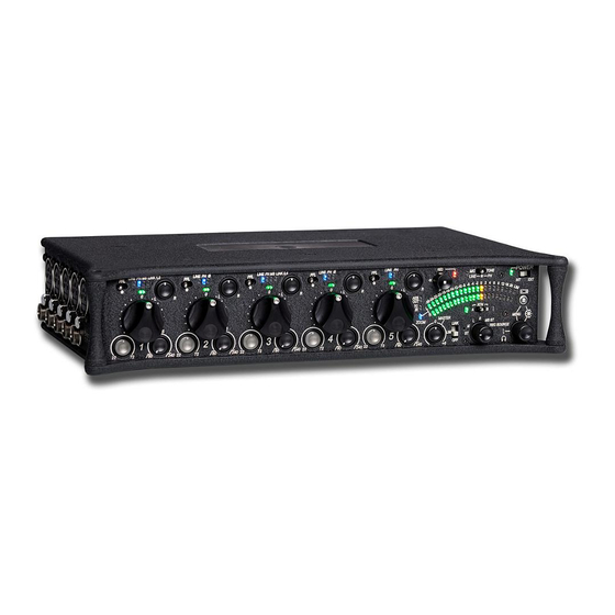
552 five-channel portable production mixer with integrated recorder
Hide thumbs
Also See for 552:
- User manual and technical information (56 pages) ,
- User manual and technical information (48 pages) ,
- Quick start manual (57 pages)
Table of Contents
Advertisement
552 Packing List
Thank you for purchasing the 552 Five-Channel Portable Production Mixer with Integrated Recorder.
Please make certain that this package contains the listed items below.
552 Five-Channel Portable Production Mixer with Integrated Recorder
1)
Printed User Guide and Technical Information
1)
Rubber Bumpers
4)
Colored Dots
6)
Purchase Registration Card
1)
Setup Menu Chart Card
1)
Front Panel Shortcuts Card
1)
Packing List (this sheet)
1)
February, 2014
Advertisement
Table of Contents

Subscribe to Our Youtube Channel
Related Manuals for Sound Devices 552


Summary of Contents for Sound Devices 552
-
Page 1: Packing List
552 Packing List Thank you for purchasing the 552 Five-Channel Portable Production Mixer with Integrated Recorder. Please make certain that this package contains the listed items below. 552 Five-Channel Portable Production Mixer with Integrated Recorder Printed User Guide and Technical Information... - Page 3 Five-Channel Portable Production Mixer with Integrated Recorder User Guide and Technical Information firmware rev. 1.4 Sound Devices, LLC E7556 State Rd. 23/33 • Reedsburg, WI • USA +1 (608) 524-0625 • fax: +1 (608) 524-0655 Toll-Free: (800) 505-0625 www.sounddevices.com support@sounddevices.com...
-
Page 5: Table Of Contents
552 User Guide and Technical Information Table of Contents Quick Start Guide . . . . . . . . . . . . . . . . . . . . . . .3 Metering . -
Page 6: Limitation Of Liability
OR ARISING OUT OF ITS CONTRACTS WITH ITS CUSTOMERS OR OTHER THIRD PARTIES. NOTWITHSTANDING AND WITHOUT LIMITING THE FOREGOING, IN NO EVENT SHALL SOUND DEVICES BE LIABLE FOR ANY AMOUNT OF DAMAGES IN EXCESS OF AMOUNTS PAID BY THE END USER FOR THE PRODUCTS AS TO WHICH ANY LIABILITY HAS BEEN DETERMINED TO EXIST. -
Page 7: Quick Start Guide
552 User Guide and Technical Information Quick Start Guide This Quick Start Guide provides a brief overview for first use of the 552. Connect power. For internal powering from AA batteries, unscrew the battery cap (counter-clock- wise), insert four AA batteries (not included) positive (+) side first into the battery tube. - Page 8 2) Slide the SLATE MIC/TONE switch left. Apply Phantom Power to an input. The 552 supplies 48 V to inputs set to receive phantom power (PH). Phantom pow- er can be set to 12 V in the Setup Menu. To apply phantom power, hold an input’s PFL switch, then slide the SLATE MIC/TONE switch to the right.
- Page 9 552 User Guide and Technical Information Set Input Faders in use to unity gain (0 dB or 12 o’clock). Faders not used should be set to off (full counter-clockwise position). Set Input Trim Levels. Push to release the recessed Trim (gain) Control. Turn the Trim Control clockwise to raise the level of the input.
- Page 10 Output Meter LEDs. The internal AA battery level is displayed on the left meter and external DC voltage level is displayed on the right meter. Connect the 552 analog outputs to the next device in the signal chain (audio recorder, wireless transmitter, or camera).
- Page 11 552 User Guide and Technical Information Voice Prompt The 552 features a Synthetic Voice for Enhanced Navigation, or SVEN. SVEN provides spoken word feedback when Setup Menu features are adjusted. He is designed to simplify control and provide important information to the user. Additionally, SVEN provides status information about the digital audio recorder and time and date information.
-
Page 12: Front Panel Descriptions
552 User Guide and Technical Information Front Panel Descriptions All 552 settings are accessed and controlled from the Front Panel. This allows the unit to be placed in a production bag while having complete control of the unit. 20 21 22... - Page 13 +20 dBu. To engage Zoom mode, press teries, the LED illuminates green when in on the Headphone Controller. the 552 is on, turns yellow when low Metering. voltage point is reached, and flashes red when voltage reaches a critical level and batteries should be changed.
- Page 14 552 User Guide and Technical Information Front Panel Descriptions cont. 20 21 22 Power Switch RTN A/B Switch Three-position slide switch, selects be- Two-position momentary switch. Slide tween internal battery power or external left for RTN A headphone monitoring, DC sources, middle position is Off.
-
Page 15: Rear Panel Descriptions
552 User Guide and Technical Information Rear Panel Descriptions SD Slot Factory Programming Port Protective rubber cover for SD (Secure Mini USB port used for initial factory Digital) memory card slot. Insert the programming. This connection has no SD/SDHC card into the slot until it sits user function. -
Page 16: Right Panel Connectors And Controls
552 User Guide and Technical Information Right Panel Connectors and Controls Mono Mic Out Tape Output Unbalanced mono mic-level output on Unbalanced tape-level stereo output 3.5 mm female connector, designed to on TA3 connector. Pin 1 = Ground, connect to wireless IFB transmitters or pin 2 = Left, pin 3 = Right. -
Page 17: Top And Bottom Panels
Voice Prompt The 552 features a Synthetic Voice for Enhanced Navigation, or SVEN. SVEN provides spoken word information in headphones when Setup Menu features are adjusted. SVEN is designed to simplify control and provide important information to the user. Additionally, SVEN provides status informa- tion about the digital audio recorder and time and date information. -
Page 18: Input Setup And Control
The inputs of the 552 can be used as balanced or unbalanced. To unbalance, tie pin-3 to pin-1 of the XLR connector. There is no change in gain between unbalanced and balanced connections into the 552. -
Page 19: Phantom Power
Make certain to disable phantom power with Line-level output devices that are susceptible to damage from DC. The 552 can provide up to 10 mA to each input at 48 V, sufficient for the most power-hungry con- denser microphones. Many phantom powered microphones do not require 48 V and can be properly powered with 12 V. -
Page 20: Gain - Trim And Fader Relationship
(0 dB or 12 o’clock), make the appropriate adjustments using the Trim control. Once the coarse gain is set to the desired level, recess the Trim control to hide it from the 552’s mixing surface. Trim level is adjustable from 22 to 72 dB of gain. -
Page 21: High-Pass Filter
When possible, attempt to equalize at the sound source with microphone selection, placement, windscreens, and onboard microphone filtering. Many microphones have on-board high pass filters. Use the high-pass filters on the 552 in conjunction with the microphone’s filter to increase the filter’s slope. -
Page 22: Pan Control
Stereo Linking The Stereo Link feature allows two pairs of 552 inputs to be linked as stereo pairs. These are inputs 1,2 and inputs 3,4. In the Setup Menu inputs can be linked as either a Stereo Pair or an MS Stereo Pair. -
Page 23: Output Setup And Control
552 User Guide and Technical Information Output Setup and Control The 552 has stereo output bus that feeds multiple outputs. Additionally, each 552 input has its own direct output. This output flexibility is essential for complex, multi-camera productions. Master Gain Control The Master Gain Control adjusts the overall output level of the left and right outputs. -
Page 24: Hirose 10-Pin
Tape Outputs are typically used to interface with consumer devices such as MiniDisc and compact transcription recorders. The 552 includes two unbalanced tape level outputs, a TA3 connector and a 3.5 mm jack. These two connectors are resistively in parallel and are isolated from the balanced outputs. -
Page 25: Limiters
When the 552 Limiters are engaged, it is nearly impossible to clip (overload) the 552 mixer. Activate the 552 limiters by setting the front-panel “LIM” switch to either LINK or ON. This enables both the input and output limiters and determines the behavior of the output limiter. Sound Devices recom- mends that the limiters be active at all times. -
Page 26: Lim And Link
At Factory Default, the mixer is set to limit the output signal peak levels to +20 dBu. This assures that the output of the 552 will not overload inputs that accept full line-level signals. The orange LIM LEDs, located at the end of the meter scale, illuminate in various intensities to repre- sent output limiting. -
Page 27: File Format
2^16 (65,536) possible values. 24-bit audio has a word length of 2^24 (16.7 million) possible values per sample. Sampling Rate The 552 records WAV files at the sampling rates selected below. The sampling frequency is set in the Setup Menu. • 44.1 kHz •... -
Page 28: Recording Media
The SD slot is located on the 552’s Rear Panel. It is protected by a rubber cover. Gently pry the pro- tective rubber cover from left to right to expose the SD Slot. Insert the SD card into the slot. The card should glide smoothly into the slot. -
Page 29: Folder Structure
Automatic File Splitting While it is possible to have thousands of files on the 552 SD card, the largest any single file may be is 2 GB. The 552 automatically splits an audio file before the 2 GB size is reached and begins writing to a new file. -
Page 30: Recorder Controller
The Record LED indicates the overall media status. When no media is present or detected the LED flashes yellow. The LED will be off when media is attached and ready. When the 552 is actively recording the LED illuminates solid red. When recording is paused or in the event that a record command is given and the media is not ready, the LED flashes red until the recorder actively starts recording. -
Page 31: Record Mode
Time Code Time Code Mode is set to off at factory default. When Time Code Mode is set to off the 552 stamps a start time code value that is derived from the time-of-day clock to the “BEXT” chunk of the recorded WAV file and no frame rate information is written. -
Page 32: Sampling Rate
Playback After a file has been recorded, the 552 can play back the file. The last file recorded is always the file that is immediately available for playback. Playback audio is sent to the headphone monitor. The Headphone Selector position determines the monitoring behavior. -
Page 33: Metering
In VU mode, the front panel meter labeling is in volume units. VU meters are always referenced to an actual signal level in dBu, the 552 VU meter is referenced with 0 VU corresponding to 0 dBu at the Line-Level outputs. -
Page 34: Peak Hold + Vu
0 dBu, the Meter Reference Level can be adjusted so that a displayed value of 0 dBu (peak or VU) on the 552 meters will correspond to a higher level on the outputs of the 552. The Meter Refer- ence Level can be adjusted in the setup menu. -
Page 35: Headphone Monitoring
Headphone Controller, the headphone gain level is temporarily displayed on the Right Output Meter. The 552 can drive headphones to dangerously high volumes. Turn down the headphone gain before selecting a headphone source to prevent accidental signal extremes. Headphone Source Selection... -
Page 36: Rtn A And B
Return Loopback During typical operation the 552’s Left and Right output buses are sent to both the Tape outputs and the Mono Mic output. When set, Return Loopback allows Return A or Return B to be directly routed to the Tape and Mono Mic outputs. -
Page 37: Powering
552 is powered down and batteries are changed. External Powering The 552 can be powered from any DC voltage from 10 to 18 VDC. Pin-4 of the locking, Hirose con- nector is positive (+) and pin-1 is negative (–). The external DC supply is fully isolated (floating) from the rest of the mixer for easy and safe interconnection with other external audio gear. -
Page 38: Power Consumption
Power Consumption The 552 varies in the amount of current it draws. Several features of the 552 directly affect current draw in different ways. The following list highlights the larger current drawing functions. 1. Microphone powering - the main source of extra 552 current draw. -
Page 39: Tone Oscillator
Tone Oscillator Tone is used to set gain structure between the 552 and the next device in the signal path. The tone oscillator uses the right position of the slide switch. Slide right to activate, hold for two seconds to latch on. - Page 40 If the slate mic is disabled in the Setup Menu, the “all call” is also disabled. The following diagram illustrates a wireless Talk Back setup using a Sound Devices MM-1. v. 1.4 Features and specifications are subject to change. Visit www.sounddevices.com for the latest documentation.
-
Page 41: Time Of Day/Date Clock
552 User Guide and Technical Information Time of Day/Date Clock The 552 has a built-in time-of-day/date clock used to stamp recorded files with the time recorded. All clock references are in 24-hour format. To check the current time, press-and-hold the Battery Check button. If an SD card is inserted, the Remaining Record Time will precede the Time and Date announcement. -
Page 42: Linking To Other Mixers
To Link two 552s together: Connect the Link I/O of 552 A to the Link I/O of 552 B using a TA5F to TA5F cable (Sound Devices XL- TA55 optional accessory). This will send the stereo mix of each 552 directly to the stereo output bus of both 552s. -
Page 43: Accessing The Setup Menu
Setup Menu Function. User Settings The 552 can save and recall a User Setup File from the SD card or its internal memory. User Setup Files contain all settings made in the Setup Menu and all Input Settings including, input type, phan- tom power, and polarity. -
Page 44: Factory Default Settings
552 User Guide and Technical Information Press the Battery Check Button. To cancel, press the Stop key. If neither button is pressed in five seconds, the load settings function is canceled. If loading user settings, wait until SVEN announces “Load com- plete”... - Page 45 • 12 Volts (-24) selected the overall power consumption • 48 Volts Line (-22) of the 552 is lowered. Line options allow • 12 Volts Line (-20) phantom to be applied to both Mic- and Line-Level inputs. Using phantom power on microphones at Line-Level is useful in high SPL environments.
-
Page 46: Front Panel Button Shortcuts
• Full range DC Input (-20) • 14 Volt Lithium Ion (-18) Front Panel Button Shortcuts To speed navigation the 552 has numerous navigation “shortcuts”. For combinations, press and hold down the first identified key then press the next identified key(s). Function... - Page 47 552 User Guide and Technical Information Function Key Sequence Action Meter Zoom Press the Headphone Controller Toggles Meter Zoom on and off. When on, the resolution of the Output Meter is increased and ranges from 0 to 20 dB. 3 .5 mm HP Gain...
-
Page 48: Connector Pin Assignments
Key Sequence Action Save User Hold PFL 2 and press the Stop button Setup to Inter- Saves User Settings to the internal memory of the 552. nal Memory Load User Setup Hold PFL 2 and press the Headphone Controller from Internal Recalls User Settings from the internal memory of the 552. -
Page 49: Specifications
XLR Line: Transformer-balanced for use with ≤2k ohm outputs www.sounddevices.com RTN A,B (3.5 mm/TA3/10-pin): Unbalanced stereo for use with ≤2k ohm outputs Link I/O: Unbalanced stereo for linking to Sound Devices 302, 442, 552, and MixPre. Input Impedance XLR Mic: 2k ohms... -
Page 50: Analog Outputs
552 User Guide and Technical Information Input Limiters Affects the output of the mic preamps only ('Trim' stage), +18 dBu threshold, 20:1 limiting ratio, 1 mS attack time, 500 mS release time. Analog Outputs XLR Line: Transformer-balanced for use with ≥600 ohm inputs Output Type XLR -10: Transformer-balanced for use with ≥10k ohm inputs... -
Page 51: Dimensions And Weight
552 User Guide and Technical Information A/D Dynamic Range 103 dB, A-weighted bandwidth typical Media Type Secure Digital High Capacity (SDHC), Secure Digital (SD) FAT32 formatted, will format media on-board File Type WAV - 2-Track Polyphonic, 16 bit, 24 bit... -
Page 52: Block Diagram - Inputs And Outputs
552 User Guide and Technical Information Block Diagram - Inputs and Outputs v. 1.4 Features and specifications are subject to change. Visit www.sounddevices.com for the latest documentation. -
Page 53: Block Diagram - Monitoring
552 User Guide and Technical Information Block Diagram - Monitoring... -
Page 54: Block Diagram - Aes
552 User Guide and Technical Information Block Diagram - AES v. 1.4 Features and specifications are subject to change. Visit www.sounddevices.com for the latest documentation. -
Page 55: Accessories
552 User Guide and Technical Information Accessories Several high-value accessories are available for the 552, including production cases, cables, and power accessories. For a full list of Sound Devices products and accessories, visit our web site www.sounddevices.com/products. Optional 552 Related Accessories... -
Page 56: Wave Agent
552 User Guide and Technical Information Wave Agent Wave Agent Beta is a WAV file librarian for Mac OS and Windows computers. Designed for Produc- tion Sound Mixers and Post Production Editors, Wave Agent provides a comprehensive and indis- pensable range of tools for preparing audio files for problem-free passage through complex produc- tion workflows. -
Page 57: Ce Declaration Of Conformity
According to ISO/IEC Guide 22 Sound Devices, LLC 300 Wengel Drive Reedsburg, WI 53959 USA declares that the product, 552 Five Channel Portable Production Mixer with Integrated Recorder is in conformity with and passes: EN55103-1, 1997 EMC-product family standard for audio, video, audio-visual and entertainment lighting control apparatus for professional use. -
Page 58: Warranty And Technical Support
Sound Devices cannot guarantee that a given computer, software, or operating system configuration can be used satisfactorily with the 552 Mixer based exclusively on the fact that it meets our minimum system requirements. v. 1.4 Features and specifications are subject to change. Visit www.sounddevices.com for the latest documentation. - Page 60 552 rev. 1.4 - Printed in U.S.A.
Need help?
Do you have a question about the 552 and is the answer not in the manual?
Questions and answers