Sound Devices 688 User Manual
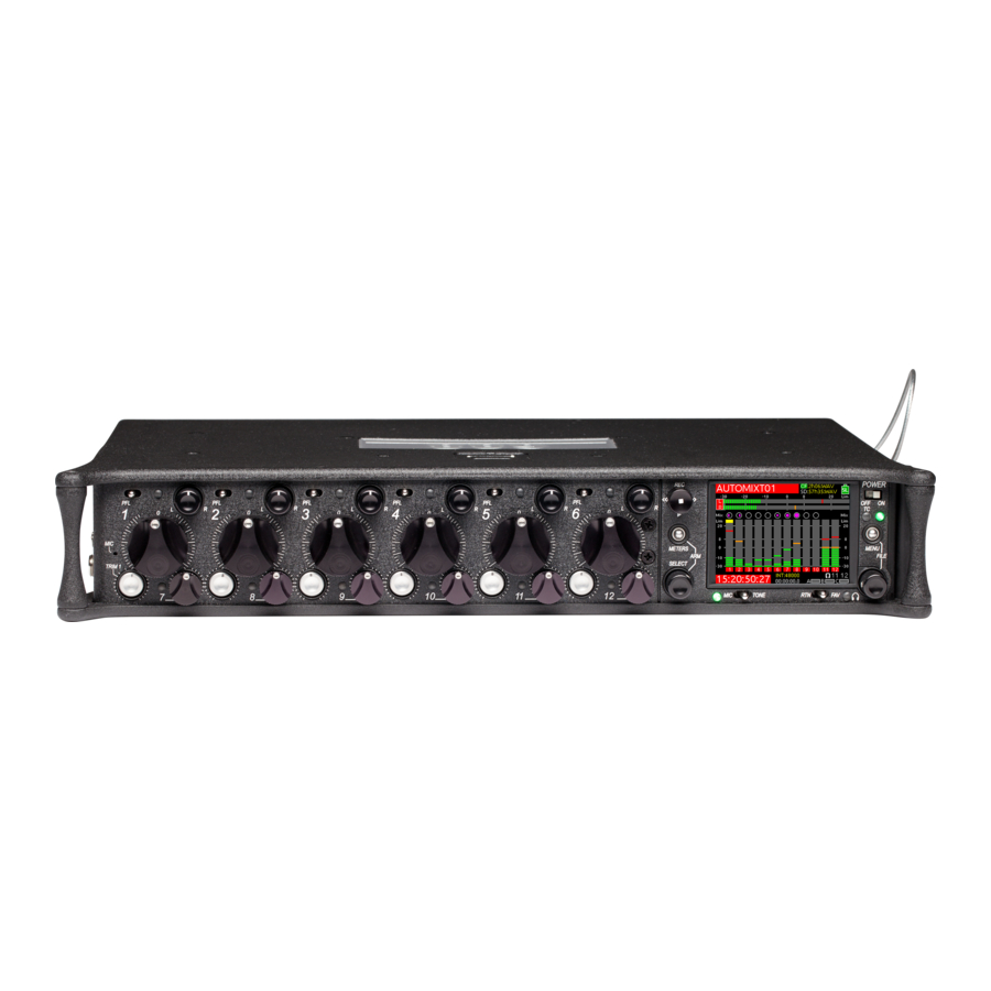
Field production mixer with integrated recorder and mixassist
Hide thumbs
Also See for 688:
- User manual (142 pages) ,
- Quick start manual (12 pages) ,
- User manual (129 pages)
Table of Contents
Advertisement
Advertisement
Table of Contents

Related Manuals for Sound Devices 688


Summary of Contents for Sound Devices 688
- Page 1 Field Production Mixer with Integrated Recorder and MixAssist™ User Guide...
- Page 2 Microsoft Corporation in the U.S. and other countries. All other trademarks herein are the property of their respective owners. 688 User Guide • Rev 4-G • July 27, 2021 FCC Notice This device complies with part 15 of the FCC Rules.
- Page 3 Revision History This table provides the revision history and cross-reference links to “what’s new” in this guide. Rev# Date Firmware Description Version 1-A; 1-B March 2015 v1.00 Preliminary Draft; Initial Offi cial Publication June 2015 v2.00 Added Firmware updates for v2.00, including new SL-6 chapter 2-B;...
-
Page 4: Table Of Contents
Power Powering the 688 ....... 25 PowerSafe ........28 Using External Power . - Page 5 Editing Metadata in Other Programs ....104 Editing Metadata on the 688 ....100 Using the Phrase List for Notes .
- Page 6 System Setting up Tones and Bells ..... . . 105 Calibrating Faders & Pans ..... . . 111 Confi guring Record/Stop and Warning Bells .
- Page 7 Quick Routing of L and R Tracks ....208 Trim Levels (688 only) ......207 Specifi cations .
-
Page 8: Overview Of Chassis
Overview of Chassis The 688 chassis is made of light-weight Topics in this section include: and durable carbon-fi ber. Front, Top, and Bottom Panels The front panel of the chassis features Left Side Panel several easy-to-reach controls, Right Side Panel... - Page 9 MIC/TONE Switch RTN/FAV Switch EATURE ESCRIPTION Power Switch and LED Powers 688 on and off, and indicates power status. Timecode LED Flashes blue to indicate whether the internal timecode generator (and QuickBoot) is active while the mixer is off. Menu Button Provides access to the Main menu.
- Page 10 fl ashes yellow when an input’s PFL is active. Because the CL-6 accessory provides separate PFL switches for inputs 7-12, when the CL-6 is attached to the 688, the dual-functionality of the six PFL switches on the 668 changes. Slide left activates PFL and slide right displays Input Settings for inputs 1-6 only.
-
Page 11: Left Side Panel
User Guide Left Side Panel XLR Inputs TA3 Inputs Headphone Outputs EATURE ESCRIPTION XLR Inputs Active-balanced analog microphone- or line-level inputs. Inputs 1 and 6 can also accept AES3 or AES42 (Mode 1) signal. [Pin-1 = ground, pin-2 = hot (+), and pin-3 = cold (-)] TA3 Inputs Active-balanced analog line-level inputs. - Page 12 SD Card Slot Accepts SD/SDHC/SDXC cards with the notched corner oriented to- ward the top of the 688. High speed class 10 cards are recommended. Insert until it clicks securely in the slot. The card should glide smoothly into the slot. Press to eject.
-
Page 13: Back Panel
User Guide Back Panel The back panel contains BNC word clock connections: Word Clock Input Word Clock Output EATURE ESCRIPTION Word Clock Input Accepts word clock rates between 44.1 kHz and 192 kHz for synchro- nizing the internal recorder to external digital audio devices. Word Clock Output Provides word clock signal to synchronize external digital audio de- vices. -
Page 14: The Lcd And User Interface
Meter Views The 688 displays important metering information at a glance on its LCD. All meter views provide various combinations of input, track, and return meters. By default, the fi rst of three predefi ned meter views is shown. This view is known as the Main screen. -
Page 15: Using Meter Views
Customizing Meter Views While the 688 provides three meter views by default, all three may be custom- ized to display the information you deem most important. The second and third meter views may also be turned off so that only one meter view is shown as the Main screen at all times. -
Page 16: Accessing The Main Menu
THE LCD AND USER INTERFACE Accessing the Main Menu The majority of the 688’s settings are confi gured with the Main menu. To access the Main menu: MENU Button Press the MENU button. The Main menu is made up of categories, each with its own set of sub-menu options. -
Page 17: Customizing The Lcd And Leds
User Guide Customizing the LCD and LEDs Because the 688 is a portable fi eld mixer, it may be used in a variety of environ- ments, including some where lighting is an issue that requires adjustments to the mixer. With some System settings, you can modify the brightness levels of the LCD, the brightness levels of the LEDs, and even enable or disable the LCD Daylight mode. -
Page 18: Headphone Monitoring
Connect headphones to either the 1/4-inch or 3.5mm headphone outputs, lo- cated on the left panel of the 688. ⚠ The 688 can drive headphones to dangerously high vol- umes. Turn down the headphone gain before attaching headphones or selecting a headphone source to prevent accidental high levels. -
Page 19: Selecting Headphone Source
User Guide Selecting Headphone Source The default list of headphone presets consists of six predefi ned headphone sources and 10 customizable presets. The predefi ned headphone sources are: HP S OURCE ESCRIPTION LR ST Master bus in stereo. LR Mono Master bus summed mono to both ears. -
Page 20: Confi Guring The Headphone Preset List
HEADPHONE MONITORING Confi guring the Headphone Preset List Presets can be excluded from this list to make preset selection simpler. To edit the Headphone Preset list: 1. Press the MENU button. Turn and press the Headphone encoder to select SYSTEM > Headphone Preset List. -
Page 21: Defi Ning Custom Headphone Presets
User Guide Defi ning Custom Headphone Presets In addition to the six predefi ned headphone sources, 10 options are available as custom headphone presets. To customize a headphone preset: 1. Press the Headphone encoder to display the list of available sources. Turn the encoder to choose one of the 10 customizable preset options, such as HP Preset(1). -
Page 22: Choosing A Favorite Headphone Preset
Slide the RTN/FAV switch right to set the highlighted Headphone preset as your new favorite. Using Headphone Source Shortcuts There are a total of four headphone monitor shortcuts on the 688. By default, these shortcuts go to: RTN A, RTN B, COM RTN, and the headphone source set as favorite. -
Page 23: Headphone Peak Led
User Guide Headphone Peak LED The Headphone Peak LED, located just left of the Headphone encoder, illumi- nates red to indicate headphone output is approaching clipping level. Monitoring without a visual indication of headphone clipping can mislead a sound mixer into thinking the output or return feeds are distorted. -
Page 24: Power
10-second power reserve that safely stops recording and shuts down in the event of a power loss. Powering the 688 The 688 operates on either external DC power or internal AA battery power. Power LED Power To turn on the 688: Flip the Power switch to the ON position. -
Page 25: Using External Power
Pin-4 of the locking, Hirose connector is positive (+) and pin-1 is negative (-). Using Battery Power The 688 uses fi ve AA batteries as a backup to external power. Alkaline AA bat- teries may be used with the 688; however, NiMH batteries are the preferred type because they provide for longer run times compared to Alkaline batteries. -
Page 26: Confi Guring Power Settings
PowerSafe shutdown occurs automatically. Confi guring Power Settings The 688 allows you to confi gure the type of external power source and what the mixer should do in the event of an unintentional power loss. To confi gure Power settings: 1. -
Page 27: Powersafe
PowerSafe™ circuitry activates. The 688 displays a warning, stops any ac- tive recordings, fi nishes writing fi les, and shuts down. The PowerSafe battery powers the 688 during this time. This feature ensures that fi les are protected even in the event of unexpected power loss. -
Page 28: Quickboot
QuickBoot™ circuitry is enabled for two hours after the 688 is powered down. During this time, the 688 can turn on and start recording in less than two sec- onds. Each time the 688 is turned on and off, the two-hour timer is reset. Be- yond the two-hour mark, QuickBoot is deactivated, so powering up results in a normal, slightly longer boot-up process. -
Page 29: Power Consumption
User Guide Power Consumption Many factors infl uence the rate at which the 688 uses battery power (current draw). The following list highlights the larger current drawing functions. • Microphone powering — The main source of extra 688 current draw. 48 V Phantom can draw a large amount of current depending on what model mi- crophone is used. -
Page 30: Inputs
Inputs The 688 has 12 analog inputs, which are Topics in this section include: assignable pre- or post- fade to outputs Physical Input Controls for optimum routing fl exibility. Activating an Input The inputs include six high-bandwidth Accessing the Input Setting Screens... -
Page 31: Activating An Input
• Blinking Yellow: Input soloed (PFL) in headphone monitors. Activating an Input The 688 has six dedicated Trim controls on the front panel. To activate an input: 1. If the Trim control for an Input is recessed, push it in and it will pop out. -
Page 32: Setting Input Source
INPUTS Channel number Channel name Input level meter Trim gain value Fader gain value HPF setting Input source setting X1 / X2 routing L / R routing Input Settings screen for inputs 1 through 6 include an INV option for inverting phase. -
Page 33: Setting Input High-Pass Filters
User Guide NPUT YPES Channel 1 OFF, MIC, MIC-PH, LINE, LINE PH, AES 42, AES 3 Channel 2 OFF, MIC, MIC-PH, LINE, LINE PH AES 42, AES 3 is conditionally available only if Channel 1 is already set to AES 42 or AES 3 Channel 3 OFF, MIC, MIC-PH, LINE, LINE PH Channel 4... -
Page 34: Setting L, R, X1, And X2 Routing
INPUTS Setting L, R, X1, and X2 Routing Routing of inputs to L, R, X1, and X2 tracks can be adjusted quickly from the Input Settings screen. An input’s routing to a track is indicated on the Input Settings screen with labels in the bottom left (X1/X2) and bottom right (L/R) of the LCD. -
Page 35: Inverting The Phase
User Guide Inverting the Phase Phase inversion is available on all 12 channels of the 688, but the process for inverting the phase varies depending on the channel. To invert the phase of channels 1 through 6: 1. Slide the PFL switch left to access the Input Settings screen for the chosen input (1-6). -
Page 36: Adjusting Trim And Fader Controls
If the SL-6 accessory is attached, the trim level for all inputs 1-12 are adjustable from -20 to +38 dB. Trim level is adjustable from 0 to 60 dB when the A20-Mini signal is received by 688 via the A10-RX and SL-6. See SL-6 GainForward. -
Page 37: Adjusting Trim - Inputs 7-12
Inputs 1-6 have dedicated Trim controls, but that is not the case for inputs 7-12. By attaching the optional CL-6 accessory, which provides additional dedicated controls, the functionality of the Mini-faders on the 688 changes to become Trim controls. To adjust trim for inputs 7-12: 1. -
Page 38: Confi Guring Linking
INPUTS MENU ESCRIPTION PTIONS Channel Linking Sets channel linking for each input pair: • Unlinked 1-2, 3-4, 5-6, 7-8, 9-10, 11-12. • [ch#-ch#] • [ch#-ch#]MS ch# represents the numerical value of the selected input pair. MS stands for Mid-Side. Phantom Voltage Globally adjusts voltage level of phantom •... -
Page 39: Confi Guring Phantom Voltage
2 and pin 3 of an input’s XLR-3F connector, relative to pin 1. In this confi guration, there is no voltage difference between signal pins 2 and 3. On the 688, the factory default sets phantom power voltage to 48 volts, but that may be changed. -
Page 40: Confi Guring The Pfl Toggle Mode
By default, access to PFL and the Input Settings screen for inputs 1-12 can be achieved with one hand. This is called 12-Channel mode. However, the PFL switches on the 688 may be confi gured to focus operation solely on inputs 1-6, while leaving inputs 7-12 accessible via a button combina- tion. -
Page 41: Confi Guring Input To Iso Routing
User Guide Confi guring Input to ISO Routing By default, each input is routed to its associated ISO track pre-fade (The fader does not affect the signal on the ISO track). This routing can be confi gured (on a per-input basis) to be post-fade (The fader does affect the signal on the ISO track). -
Page 42: Outputs
Sending Tone to Outputs Output Connections On the 688, the Left and Right XLR-M and Hirose 10-pin connectors are each transformer balanced from separate windings. This improves isolation from po- tential interference. Aux outputs X1 to X4 use active-balanced TA3 connections. -
Page 43: Accessing Output Settings
Accessing Output Settings The Main menu has a sub-menu of settings related to outputs. These may be used to customize the confi guration of the 688 outputs. To access Outputs sub-menu: 1. Press the MENU button. Turn and press the Headphone encoder to select OUTPUTS. - Page 44 OUTPUTS MENU ESCRIPTION PTIONS Linking Choose which output pairs are linked for • Linked the purpose of arming and level adjust- • Unlinked ment. (L/R, X1/X2, X3/X4, X5/X6) Levels/Type Select the nominal level of analog outputs • Mic or switch the output to send AES digital •...
-
Page 45: Confi Guring Output Linking
User Guide Confi guring Output Linking Output linking allows the gain, delay, and track arm status (L, R, X1, X2 only) of an output pair to be controlled with only one action. By default, the output gain of L/R and X5/X6 are linked and X1-X4 are unlinked. L/R, X1/X2, X3/X4, and X5/X6 pairs can be linked or unlinked from the Main menu. -
Page 46: Accessing Aes Output Routing Screen
OUTPUTS Accessing AES Output Routing Screen There is a total of 8 channels of digital output on 4 connections. Each of the XLR-3M or 10-pin A outputs can be confi gured to output AES3 digital signals. For more information, see Setting Output Type and Nominal Level. -
Page 47: Accessing Aux (X1 - X6) Routing Screen
User Guide Accessing Aux (X1 - X6) Routing Screen X1 and X2 tracks are routed to their respective outputs by default. Output sources are confi gured in the Output routing screen. To access the Aux Output Routing screen: 1. Press the MENU button. Turn and press the Headphone encoder to select OUTPUTS >... - Page 48 OUTPUTS The X1 and X2 Output Routing screens differ from the other Output Routing screens. Aux and HP sources are not available, but an additional Input Setting appears: Locked Unlocked When Input Setting is set to Locked, changing the X1 and X2 routing from the Input Settings screens is disabled, preventing accidental routing of channels to those outputs using the MIC/TONE switch.
-
Page 49: Auto-Mute Aux Output
User Guide Auto-Mute Aux Output The Auto-Mute feature silences the X1-X6 outputs on the 688 while in stop mode. This maintains privacy when not rolling on set. Auto-Mute is assignable per aux output, and audio returns to the aux outputs during playback and re- cord. -
Page 50: Enabling Playback To Lr Outputs
OUTPUTS Routing Tape Output Tape Output is often used to send signal from a camera to a producer or director over an IFB. The default source for Tape Output is the master L and R tracks. However, any return signal can be routed to the Tape Output instead. To confi... -
Page 51: Adjusting Output Delay
User Guide Adjusting Output Delay The signal of each output can be delayed up to 417 milliseconds. This is useful while interfacing with video equipment when the audio signal is being processed faster than video, creating an audio/video offset. To adjust output delay 1. -
Page 52: Entering Return Loopback Mode
OUTPUTS Entering Return Loopback Mode Return Loopback mode temporarily replaces the output source with the selected RTN signal. This is useful for sending camera audio playback to a producer or director. To enter Return Loopback mode: Press MENU + RTN switch action. “RTN switch action”... -
Page 53: Sending Tone To Outputs
User Guide Sending Tone to Outputs The 688’s internal tone oscillator can be used to send a predefi ned tone or pulse to the mixer’s outputs to aid setup of proper gain staging with other equipment, such as cameras. The Left Indent pulsing tone is useful for identifying the left or odd Aux channel of the stereo pair on the receiving device. -
Page 54: Mixassist & Dugan Automixing
Auto Mixer Screen While the 688 is capable of auto-mixing all 12 inputs, it may be confi gured from the Auto Mixer screen to attenuate fewer inputs or none at all. The 688 also features two auto mixers: Sound Devices own automixing feature called MixAssist and Dan Dugan automixing. -
Page 55: Turning The Auto Mixer On Or Off
User Guide Turning the Auto Mixer On or Off By default, auto-mixing is turned off, but it may be turned on and any of the 12 inputs can be assigned to the Auto Mixer. See also Assigning Inputs to the Auto Mixer for more information. -
Page 56: Assigning Inputs To The Auto Mixer
Mics Attenuation. Overview of MixAssist The Sound Devices MixAssist feature auto-mixes post-fade input signals to the left (L) and right (R) buses. Other signals are not affected by MixAssist. MixAssist does not limit the number of open microphones and will allow several microphones to be open simultaneously if there are several talkers. -
Page 57: Setting Mixassist Off-Attenuation
Setting MixAssist Off-Attenuation The 688 also lets the user defi ne the amount of off-attenuation that MixAssist uses during the auto-mixing process. To set the amount of off-attenuation for MixAssist: 1. -
Page 58: Lcd Views During Mixassist Automixing
MIXASSIST & DUGAN AUTOMIXING Turn the Headphone encoder to change the setting. Range is from 6 dB to 40 dB in 1 dB increments. LCD Views During MixAssist Automixing A circle icon is displayed next to the meter for each active automixed input. When the input is open, the circle will be green. -
Page 59: Overview Of Dugan Automixing
Overview of Dugan Automixing In collaboration with Dan Dugan Sound Design, Inc., Sound Devices offers another powerful automixing option as part of the 688’s Auto Mixer. The Dugan Speech System™ uses Dugan’s own patented automixing algorithm that has been an industry standard for many decades. -
Page 60: Overview
All 688 limiters use a 20:1 compression ratio. This means that any signal that exceeds the threshold by 20 dB will exit the limiting stage at only 1 dB above the threshold. The 688 limiters have a 1 ms attack time and a 500 ms release time. -
Page 61: Adjusting The Threshold
(1 dBu increments) Linking Limiters Limiters for L, R and X1, X2 channel pairs can be linked on the 688. Anytime two limiters are linked, both channels will be limited when signal reaches the threshold in any channel of the pair. -
Page 62: Using Media
Using Media Before recording anything, install and format the media storage memory cards you intend to use in the 688. The slots for memory cards are located on the right panel behind the Media Door, which is held closed magnetically. -
Page 63: Using The Transport Control
User Guide The memory card must be formatted before recording. ⚠ Reformatting a card will erase all data on the card. To (re)format an SD or CF card: 1. Press the MENU button. Transport MENU Control Button Turn and press the Headphone encoder to select File Stor- age. -
Page 64: Arming Or Disarming Recording Tracks
Wingman Integration: 6-Series. Arming or Disarming Recording Tracks The 688 features 16 recording tracks. Each of the 12 inputs is permanently routed to its associated ISO track. Buses L, R, X1, and X2 can also be armed for recording. ISOs can be sent to both pre- and post- fade. X1 and X2 can record any combi- nation of channels pre- or post-fade. -
Page 65: Accessing Recorder Settings
Accessing Recorder Settings The Main menu has a sub-menu of settings related to recording. These may be used to customize the confi guration of the 688’s Record settings. To access the Recorder sub-menu: 1. Press the MENU button... - Page 66 RECORDING MENU ESCRIPTION PTIONS Record to CF Sets the type of fi le and which tracks to • Off record to the CF card. • Wav Poly • Wav Poly (ISOs Only) The default is Wav Poly. • Wav Poly (LR Only) •...
-
Page 67: Setting File Type And Media Track Assignment
48k. Changing the MP3 Bit Rate The 688 records MP3 fi les at a default bit rate of 320kbs, but that bit rate may be changed. A high bit rate MP3 fi le preserves more audio information with an increased fi le size. A low bit rate MP3 fi le preserves less audio information with... -
Page 68: Setting The Sample Rate
Turn and press the Headphone encoder to select a bit rate. Options include: 128, 192, and 320 kbs. Setting the Sample Rate The 688 records WAV fi les at 48 kHz sample rate by default. To set sample rate: 1. Press the MENU button. -
Page 69: F Sample Modes
MP3 recording is not allowed in “F mode”. Setting the Bit Depth The 688 records 24 bit WAV fi les by default. Bit depth defi nes the digital word length used to represent a given sample and correlates to the maximum dy- namic range that is represented by the digital signal. -
Page 70: Setting The Pre-Roll
RECORDING Setting the Pre-roll Pre-roll buffering is available on the 688 to help prevent missing record cues or up-cutting takes. By default, the pre-roll time is 0 seconds (off). When active, pre-roll begins recording at a set number of seconds preceding the record but- ton being pressed. -
Page 71: Playing Back Active Takes
User Guide Playing Back Active Takes Playback may be initiated at any time except when the 688 is recording. Unless playback is initiated from the Take List or File List, the active take will be played from the current playback card. The active take is whichever take was record- ed or played most recently. -
Page 72: Comms And Returns
The 688 incorporates a built-in slate mic and a TA3 connector for an external slate mic. The built-in mic is the default. Its audio performance is not suitable for critical recording applications;... -
Page 73: Setting Slate Mic Gain
User Guide crophones) or Ext 15V Mic (for condenser microphones). When the Slate or COM function is active, the 688 will use this microphone. Setting Slate Mic Gain The gain of the slate mic is 36 dB by default. If this gain is too high, it can be... -
Page 74: Using The Slate For Notation
Private Comms The 688 features Comms for private communication between the 688 operator and other members of the crew. The most common use of Comms is for the sound mixer to communicate with the boom operator. The same mic used for slate is also used to send comms. -
Page 75: Monitoring Com/Rtn
Comms / Returns Settings The 688 has a COMMS/RETURNS menu to allow for various setting adjustments. Most of these settings are described in greater detail in other sections of this guide, where applicable. The menu’s entire sub-menu listing and options are provided in the following reference table as a convenience. -
Page 76: Adjusting Com Return Gain
COMMS AND RETURNS MENU ESCRIPTION PTIONS Slate/Com Mic Gain Sets the input gain for external and inter- • 0-56 dB nal slate microphone. Default is 36 dB. (1 dB increment) Slate Routing Select which tracks and outputs the slate mic signal is routed to. Com Return Gain Sets the gain of the COM RTN. -
Page 77: Customizing Mic/Tone And Rtn/Fav
User Guide To adjust comms muting behavior: 1. Press the MENU button. Turn and press the Headphone encoder to select COMMS/RETURNS > COM Mutes Output Program. Turn the Headphone encoder to set the value to Yes or No. Press the Headphone encoder to accept the value. Customizing MIC/TONE and RTN/FAV The primary and secondary actions of the MIC/TONE and RTN/FAV switches may be altered to fi... -
Page 78: Timecode And Sync
fi le’s duration is always an integer number of seconds long. If necessary, pre-roll and post-roll is dynamically applied to accomplish this, simplifying syn- chronization in post-production. The timecode value and frame rate of the 688 are displayed on the Main screen. -
Page 79: Setting The Timecode Mode
User Guide Setting the Timecode Mode The Timecode mode determines if the mixer generates or reads timecode from an external source, and when timecode runs and stops. To set the Timecode mode: 1. Press the MENU button. Turn and press the Headphone encoder to select TIMECODE/SYNC > Time- code Mode. - Page 80 This is useful when work- ing with wireless timecode sources, allowing the mixer to free-wheel through wireless dropouts. In the event of a dropout, the 688 will stop recording when it receives a stationary value.
-
Page 81: Setting The Frame Rate
User Guide Setting the Frame Rate By default, the 688’s frame rate for the timecode generator is set to 30nd. The frame rate value is stored in the Frame Rate fi eld of metadata. When using an external timecode mode, ensure the mixer’s frame rate is equal to (or cross-jam compatible to) the external frame rate. -
Page 82: Jamming The Timecode
TIMECODE AND SYNC Jamming the Timecode The Jam Received TC screen (better known as the Timecode Jam menu) dis- plays detailed information about the mixer’s internal SMPTE timecode generator and SMPTE timecode present on the mixer’s timecode input. It also features a button allowing you to jam the timecode if necessary. -
Page 83: Setting User Bits
A fourth mode allows user bits to be derived from an external source. If that mode is to be used, ensure the external source for timecode user bits is at- tached to the 688 via the 5-pin LEMO connector on the mixer’s right panel be- fore setting the mode. -
Page 84: Setting Display Mode
The Word Clock BNC input connection on the back panel may be used to clock from an external signal. The 688 internal word clock may also be used as clock master by connecting its output connection to external audio devices. -
Page 85: Setting Word Clock Sensitivity
Turn and press the Headphone encoder to select TIMECODE/SYNC > Sync Reference. Set the sync reference to Word Clock. When the 688 is locked to external word clock, it is indicated by WCK in yellow text at the bottom of the Main screen. Wordclock value If no valid external word clock is present, the word UNLOCK blinks yellow and red on the Main screen. -
Page 86: File Storage
fi le extension: S01T01_3.WAV scene number extension take number track designator The track designators are associated with the 688 tracks. This differs from track names which may be edited and are covered in depth in the Metadata section of this guide. -
Page 87: Transferring Files To Pc
When fi nished recording, and the media remaining time on the Main screen is white, you may remove the SD or CF card(s) from the 688 and mount them to any computer and transfer your recorded fi les using a card reader or card slot. -
Page 88: Take List And File List
FILE STORAGE Take List and File List A fi le is an individual fi le stored on attached media. A take is a single recording that can consist of multiple fi les on one or both media. The Take List displays a list of takes and provides functions for deleting, renaming, and editing informa- tion in metadata fi... -
Page 89: Deleting Files Or Folders
User Guide Turn and press the Headphone encoder to select CF or SD and view its con- tents. A list of fi les on that card will be displayed. Folder names are preced- ed by a slash (“\”). File list of CF root File list within a folder (named “Dune”) Turn the Headphone encoder to highlight a chosen fi... -
Page 90: File Storage Settings
FILE STORAGE To delete a fi le or folder: 1. From the File List, turn and press the Headphone encoder to select CF or SD. A list of fi les on that card will be displayed. Turn the Headphone encoder to highlight the chosen fi le or folder. Slide the RTN/FAV switch left or right to access options for the highlighted fi... -
Page 91: Setting Folder Options
• Either Scene or Daily File Playback Mode Determines what (if any) playback action • Play Once the 688 will perform upon reaching the • Play All end of a fi le during playback. • Repeat One • Repeat All Default Playback Card The source media that fi... - Page 92 When the Mid-level folder is set to <Daily>, a folder will be created auto- matically and named according to the date. Whenever a new day occurs, the 688 will prompt the user to confi rm the creation of a new daily folder. •...
-
Page 93: Generating Sound Reports
User Guide Generating Sound Reports The 688 can generate sound reports as a comma separated values (CSV) fi le. CSV fi les can be opened and edited by any common spreadsheet application such as Microsoft Excel , OpenOffi ce™ Calc, Apple Numbers, Google Docs™,... -
Page 94: Changing The Take Designator
FILE STORAGE Changing the Take Designator The default take designator of fi le names is the capital letter T, but that may be changed to a hyphen or any letter of the alphabet. To change the take designator: 1. Press MENU. Select FILE STORAGE >... -
Page 95: Setting Scene Increment Mode
User Guide Setting Scene Increment Mode The 688 provides a Scene Increment shortcut, but it is disabled by default. Scene names will not increment unless the Scene Increment mode is enabled. Shortcuts for a description of all time-saving shortcuts. To enable Scene Increment mode: 1. -
Page 96: Setting File Playback Mode
FILE STORAGE Setting File Playback Mode When playback is initiated, the selected fi le will play to the end and then stop— unless, of course, playback is stopped prematurely by manually pressing the Transport control in twice. This default behavior is called Play Once, but it may be modifi... -
Page 97: Erasing / Formatting Media
User Guide Erasing / Formatting Media Before recording to CF or SD media, cards must be formatted by the 688. To format media: 1. Press the MENU button. Turn and press the Headphone encoder to select FILE STORAGE. Do either of the following: Select Erase/Format CF to reformat a CompactFlash card. -
Page 98: Metadata And Take List
A take can Take List Overview consist of multiple metadata fi les. Accessing the Take List The 688 Take List allows the sound Playing Takes mixer to enter and edit the metadata Editing Metadata on the 688 of broadcast WAV fi... -
Page 99: Accessing The Take List
Push down the Transport control to begin playback. The Main screen is dis- played, and playback begins. Editing Metadata on the 688 Notes, Scene, Take, Circle Status, Folder (tape), Project, and all track names may be edited directly from the Take List for next or previous takes. -
Page 100: Using The Phrase List For Notes
Using the Phrase List for Notes Often, the same word or phrase is used for Notes on many different takes. To save time on metadata entry, the 688 provides the ability to create a phrase list for rapid retrieval and usage. -
Page 101: Clearing Scene List
User Guide Slide the FAV switch right to select OK and save the new entry. To edit or delete a phrase list entry: 1. Access the Phrase List screen. Turn the Headphone encoder to highlight an entry. Do either of the following: Slide the MIC/TONE switch left to delete the chosen entry. -
Page 102: Metadata Overview
Metadata is included in MP3 fi les inside the ID3 tags. Metadata in MP3 fi les can not be edited with the 688. The following table shows the ID3 fi elds that meta- data is stored in and the format in which it is stored. -
Page 103: Renaming Or Deleting Previous Takes
Editing Metadata in Other Programs Since Sound Devices recorders write metadata to WAV fi les using the Broadcast Wave File standard, many professional applications can read and edit this meta- data. Sometimes, it is useful to edit metadata in bulk after recording and before... -
Page 104: Setting Up Tones And Bells
Updating Firmware already covered elsewhere. Setting up Tones and Bells The 688’s internal tone oscillator, used for sending tone to outputs and tracks, has several settings to accommodate different workfl ows. Activating tone is explained in more detail in the... -
Page 105: Confi Guring Record/Stop And Warning Bells
User Guide ARAMETER ESCRIPTION PTIONS Tone Routing Displays the Tone Routing screen where the • Outputs: L, R, and tone signal can be routed to any output or X1-X6 track. • Tracks: L, R, X1, X2, and tracks 1-12 By default, all outputs and tracks are selected. Tone Level Sets the level of the internal tone generator. -
Page 106: Confi Guring The Meters
SYSTEM Turn and press the Headphone encoder to set a new level. Options include: Off, -60 to -12 dbFS in 1 dB increments. Setting the warning bell level also adjusts the level used for Record/Stop bells. By default, the Record/Stop bells are turned on, but they may be turned off. To turn on or off the Record/Stop bells: 1. -
Page 107: Setting Meter Ballistics And Peak Hold
User Guide PTION ESCRIPTION XAMPLE Bottom Positions track names on the lower end of the meter scale. The example shows solid meters. Bottom w/ramp Applies a gradient to the background color, and positions track names on the lower end of the meter scale. Positions track names on the higher end of the meter scale. -
Page 108: Setting Peak Hold
Setting the correct GMT time zone and daylight savings values is also vital for correct data stamping on the exFAT fi le system. The 688 has several System settings related to date and time parameters: ARAMETER ESCRIPTION... - Page 109 User Guide ARAMETER ESCRIPTION PTIONS Time Zone Sets the time zone, based on Greenwich Mean • GMT-1:00 – -12.00 Time (GMT). • GMT • GMT+1:00 – +13:00 Daylight Savings Sets whether or not daylight savings is in effect. • On Time By default, daylight savings is off.
-
Page 110: Calibrating Faders & Pans
To disable, turn and press the encoder to select Off. Calibrating Faders & Pans The 688 Faders and Pan pots come pre-calibrated to center. However, should they ever need to be recalibrated, that can be done via a System settings sub- menu option. -
Page 111: Using A Usb Keyboard
User Guide Using a USB Keyboard Included with the 688 is a USB 2.0 A (Female to Female) connector and a USB A to B cable, which may be used to connect a standard USB keyboard to the 688 mixer. -
Page 112: Viewing Version Information
Updating Firmware Periodically, Sound Devices releases fi rmware updates to improve system per- formance and expand the 688 feature set, which may be downloaded from the website and used to update the fi rmware on the mixer. It is highly recommended that users update to the latest version of fi rmware available as soon as possible. - Page 113 User Guide Follow the on-screen instructions. After the update is complete, the mixer power cycles. When it reboots, the updated version number will appear briefl y on the splash screen, and the mixer displays a message confi rming the fi rmware update.
-
Page 114: Quick Setup
Quick Setup The 688 helps improve work-fl ow Topics in this section include: effi ciency by providing users a way Saving Settings to save and load various custom Copying Quick Setup Files confi gurations as Quick Setup XML fi les. -
Page 115: Saving Settings
User Guide Saving Settings After you have confi gured the 688’s settings via the Main menu and Input Set- tings screens, you can save the confi guration as a Quick Setup fi le. To save settings as a Quick Setup fi le: 1. -
Page 116: Copying Quick Setup Files
QUICK SETUP Copying Quick Setup Files Quick Setup fi les saved on one memory card may be copied to another memory card as an additional backup. To copy fi les from one memory card to another: 1. Press the MENU button. Turn and press the Headphone encoder to select FILE STORAGE >... -
Page 117: Loading Previously Saved Settings
User Guide Loading Previously Saved Settings For fast reconfi guring of the 688, previously stored Quick Setup fi les may be easily loaded from internal locations or memory cards inserted into the mixer. To load a Quick Setup fi le: 1. -
Page 118: Front Panel Shortcuts
Shortcuts The 688 features numerous shortcuts to Topics in this section include: help speed navigation. Front Panel Shortcuts The shortcuts require either USB Keyboard Shortcuts simultaneously pressing combinations of front panel controls or using keystroke combinations when a USB keyboard is attached to the mixer. - Page 119 User Guide UNCTION EQUENCE CTION Toggle Playback Card HP + Play: Press and hold the Headphone encoder then push the Transport control downward (Play). This toggles the playback media card between SD or CF. Target media is indicated by a green back- ground on the Main screen.
-
Page 120: Usb Keyboard Shortcuts
A standard USB keyboard connects to the 688 to ease navigation and data en- try. Attach the keyboard to the 688 USB port using a USB A to USB A adapter (included). Anytime the QWERTY pop up keyboard is displayed, the USB key- board can be used to enter data. - Page 121 User Guide EYSTROKES CTION Alt + Enter Main screen: Toggles arming of selected track. Ctrl + Enter Access gain adjustment for highlighted L, R, X1, X2, X3, X4, X5, X6, or RTN track. Ctrl + Up/Down Arrows Main screen: Select tracks. Input Settings screen: Adjusts trim gain for inputs 7-12.
-
Page 122: Wingman Integration: 6-Series
Track View on iPhone or iPod Touch Start Guide, shipped with the hardware and offered as a free PDF download from the Sound Devices website. Starting Wingman Before starting the application, ensure the WM-Connect hardware accessory (shown at right) is attached to your 6-Series mixer, that Bluetooth is turned on (on your mobile device), and the mixer is both powered on and running the latest fi... -
Page 123: User Interface
User Guide When the virtual keyboard appears, enter a password. When fi nished, slide the RTN/FAV switch right (or Enter on attached USB- keyboard) to select OK. When prompted to confi rm, press the Headphone encoder to select OK again. User Interface The Wingman software application provides an easy-to-navigate, touch-screen user interface. - Page 124 WINGMAN INTEGRATION: 6-SERIES Status Bar Viewing Area Tab Bar...
-
Page 125: Transport View
This section (shown below) provides the current fi le name, as well as a bar with the following information: • a large Timecode display • a Connection icon bearing the Sound Devices logo • a smaller ABS time display • the timecode frame rate When recording, the background color of the bar turns red. -
Page 126: Connecting To A 6-Series Mixer
When running Wingman on an iPad, iPhone or iPod Touch, the Connection icon is located left of the Timecode display and bears the Sound Devices logo. The color of the icon is signifi cant, because it changes based on the connection... - Page 127 User Guide Use the Devices Found list to select a 6-Series mixer with a WM-Connect attached within range. Mixers that are within range but already connected to other Wingman applications are not visible in the Devices Found list. To switch connection to a different 6-Series mixer: 1.
-
Page 128: Using Transport Controls
WINGMAN INTEGRATION: 6-SERIES Using Transport Controls When recording is in progress, the Transport view changes slightly. For instance, the background of the Timecode display appears red as does the center dot on the Record button. Stop Button To begin recording: Tap the Record button. -
Page 129: Using Meter Views
In most cases, meters appear vertically in the Transport view; however, on the 688 or 664 as shown below, when the left and right bus tracks are displayed with ISOs, only the ISOs (1-12) are vertical, while the left and right bus tracks (LR) are positioned horizontally. - Page 130 WINGMAN INTEGRATION: 6-SERIES The three available meter views vary depending on the model of mixer to which Wingman is connected; however, the procedure for toggling through the available meter views is the same. To change the meter view: Slide a fi ngertip vertically up or down over the meters. The following table explains which pre-confi...
-
Page 131: Editing Track Names
User Guide Editing Track Names On the iPad, in the Transport view, track names appear superimposed over the meters near the meter labels, and these names may be edited directly from this view. Due to smaller screen limitations, iPhones and iPod Touch devices do not show track names in the Transport view. -
Page 132: Take List View
WINGMAN INTEGRATION: 6-SERIES Meter labels are joined (displayed as a single label) to indicate when inputs or tracks are linked. This is shown in the example; see the meter labels for the left and right buses as well as inputs 11 and 12. Take List View The Take List displays the next take, the current take, and up to 50 previous takes as a list of fi... - Page 133 User Guide Whether a take is circled will be indicated in the list with a large @ symbol, while the next and current takes are always at the top of the list and identifi ed by unique icons.
-
Page 134: Editing A Take's Metadata
WINGMAN INTEGRATION: 6-SERIES ESCRIPTION Next Designates the next take, which is always located at the top of the Take List. Current Designates the current take. The current take is the take in the process of being recorded or, if recording has stopped, it is the last recorded take. To view a take’s fi... -
Page 135: Reports View
User Guide Reports View All 6-Series mixers generate sound reports as comma separated values (CSV) fi les. These fi les, stored on CompactFlash or SD cards inserted into the mixer, may be opened and edited by many common spreadsheet applications. - Page 136 WINGMAN INTEGRATION: 6-SERIES From the Reports view in Wingman, you can modify sound report options, defi ne the headers used in sound reports, and create sound reports. Settings in the mixer’s File Storage > Folder Options determine which fi les are used to generate the report and the current record directory in which the generated report is saved.
-
Page 137: Creating Sound Reports
Also included are interactive links to the following online resources: • The WM-Connect Quick Start Guide • The Wingman User Guide • The connected 6-Series mixer’s User Guide • Link to fi le a Support Query with Sound Devices Technical Support... -
Page 138: Track View On Iphone Or Ipod Touch
WINGMAN INTEGRATION: 6-SERIES Track View on iPhone or iPod Touch Because iPhone and iPod Touch mobile devices have smaller screens, the Wingman’s user interface appears slightly different from the application when run on an iPad. The main differences lie with the Transport view, which on smaller screens does not display track names or the Metadata section. - Page 139 User Guide In the Track view, the Timecode display and toolbar with transport buttons dis- appear, and the meters are displayed horizontally full-screen, with track names superimposed over the meters. To edit track names: 1. While viewing Transport, swipe right or left to display the Track view. Tap anywhere on the horizontal meter for the track you want to edit.
-
Page 140: Third-Party Remote Control
Wireless Remote Control and Timecode Systems—Sound Devices Web-based Wireless Remote Control offers wireless remote control of any 6-Series mixer (688, 664, and 633) via iOS and web-based mobile devices. This section outlines the benefi ts and what is required for iOS and web-based wireless remote control integration. - Page 141 User Guide iOS Wireless Remote Control All 6-Series mixers support wireless remote control from iOS mobile devices, such as iPhone, iPad, or iPod Touch. This integration does require the following third-party hardware and software: ARDWARE OFTWARE ESCRIPTION :wave The :wave by Timecode Systems is a highly accurate timecode and genlock generator with integrated RF transceiver and WiFi.
-
Page 142: Ios Remote Control Connection Diagrams
THIRD-PARTY REMOTE CONTROL iOS Remote Control Connection Diagrams The following diagram shows a direct-to-mixer connection. The following diagram shows a direct-to-CL-12 connection. The CL-12 linear fader controller is an optional accessory for the 6-Series. See the CL-12 Quick Start Guide for information on connecting a CL-12 to a mixer. -
Page 143: Ios Remote Control Examples
User Guide iOS Remote Control Examples Here is an example of what the app looks like on an iPhone and iPad: Web-based Wireless Remote Control All 6-Series mixers support web-based wireless remote control via PC or Mac computers and mobile devices, such as Android or iOS smart phones or tablets, that have a web interface. -
Page 144: Web-Based Remote Control Connection Diagrams145
THIRD-PARTY REMOTE CONTROL ARDWARE OFTWARE ESCRIPTION Using the MLC-HID—a 5-pin Lemo to USB-A cable, available from Ambient—connect the ACN-ML Master Lockit to the mixer’s USB port (or to a CL-12’s USB keyboard port). When connecting directly to the mixer instead of to the CL-12, a USB A (female) to B (male) adapter is also necessary. -
Page 145: Web-Based Remote Control Examples
User Guide Web-based Remote Control Examples Here is an example of what the web interface looks like on a smart phone: Here is an example of what the web interface looks like on a PC:... -
Page 146: Analog Inputs
Specifi cations Various product specifi cations for Topics in this section include: the 688 are provided here for your Analog Inputs convenience. They relate to inputs Digital Inputs and outputs, powering, environmental Analog Outputs parameters, as well as physical aspects Digital Outputs/Recorder of the mixer. -
Page 147: Digital Inputs
User Guide Post-Fader Input Limiters • Adjustable threshold +4 dBu to +18 dBu (Inputs 1-12) • 20:1 limiting ratio • 1 mS attack time • 500 mS release time High-Pass Filters Adjustable 80 Hz to 240 Hz, 18 dB/oct at 80 Hz (Up to 96 kHz SR) Fixed 50 Hz, 6 dB/octave (192 kHz SR) •... -
Page 148: Digital Outputs/Recorder
SPECIFICATIONS Headphone Max. Gain • 63 dB (Line 1-6 Input) • 44 dB (Line 7-12 Input) • 103 dB (Mic Input) Line Output Clipping • 20 dBu minimum with 10k load Level (1% THD) Output Limiters • L/R and X1/X2, adjustable threshold from +4 dBu to +18 dBu, soft knee/hard knee •... -
Page 149: Power
User Guide Accuracy • Ambient Generator: ±0.2ppm (0.5 frames per 24 hours) • Holds TC clock for two hours after main battery removal Timecode Input • 20k ohm impedance • 0.3 V - 3.0 V p-p (–17 dBu - +3 dBu) Timecode Output •... - Page 150 Accessories The 688 works with various accessories Topics in this section include: which may be purchased separately Electronic Accessories and used to further enhance your fi eld Cables and Connectors mixing and recording experience. Cases This section is not intended to be an all-...
-
Page 151: Electronic Accessories
System. CL-6 This optional input controller attaches to the bot- tom of the 688 and adds six full-sized tactile fader controls, sunlight-viewable LED metering and big, back-lit Record and Stop controls. When the CL-6 is attached to a 688, the 688’s mini-faders, origi-... -
Page 152: Cables And Connectors
XL-2F A 25-inch XLR-3F to TA3-F cable, used to connect mixers and other devices with XLR-3M outputs to the TA3 7-12 inputs on the 688. Also used to attach standard microphone as auxiliary slate mic. Each package contains two cables. - Page 153 20-foot extension cable. The XL-10 is a high-quality multi-pin breakout and extension cable designed specifi cally for Sound Devices fi eld production mixers. It provides easy access to the balanced outputs and stereo return A and C con- nections.
- Page 154 BNC connectors, for SMTPE time- code. XL-LL LEMO-5 to LEMO-5 coiled cable for timecode inter- connection between the 688 and other devices. XL-LX LEMO-5 to XLR-3F input and XLR-3M output for timecode interconnection between the 688 and other devices.
-
Page 155: Cases
ESCRIPTION CS-688 This production case, designed by PortaBrace for Sound Devices, may be used for either the 688 or 664 and accessories, such as the SL-6 (pictured here with the 688) and CL-6. The case has sever- al attached pockets, zippered sides, a removable windowed cover, and is made from durable water- proof nylon, with anti-skid material on the bottom. -
Page 156: Sl-6 Powering And Wireless System
Each slot accepts one (single- or dual-channel) SuperSlot or unislot receiver. The connection provides power to the receiver and connects the receiver’s audio output directly to the 688. Antenna Distribution SMA connectors with right-angle adapters are used to connect receiv- leads ers to the SL-6 antenna distribution system. -
Page 157: Right Panel
(12 V) EATURE ESCRIPTION Hirose 4-pin DC Input Hirose 4-pin DC input for powering the SL-6 and 688. Power must be attached to this connector or an NP-1 battery must be inserted to power the SL-6 and 688. Coaxial DC Outputs... -
Page 158: Powering With The Sl-6
Safe™ battery will keep the SL-6 and attached devices powered for 10 seconds while recording is stopped. If any power source is attached to the 688’s external DC input, or if internal AA batteries are present, the 688 (and CL-6, if attached) will continue to operate using those power sources. -
Page 159: Power Screen
User Guide When the SL-6 is attached, the DC voltage indicator (battery icon) on the 688’s Main screen will display NP or SL to indicate which power source is active. External DC Power via SL-6 Battery Power via NP-1 in SL-6... -
Page 160: Sl-6 Power Settings
Off. To protect NP-1 batteries from exceeding their maximum discharge current, when total power draw reaches 45 watts, the 688 displays a warning message. When total power draw reaches 50 watts (SWIT battery) or 53 watts (IDX bat- tery), the DC outputs will be turned off in descending order (output 4 - 1) until power draw drops below 45 watts. -
Page 161: Turning Off Power To Rx Slots
User Guide Turning Off Power to Rx Slots When the SL-6 is attached, the 688 provides a sub-menu option that lets users power off unused receiver slots in the SL-6. Sound Devices recommends that you do not manually power on or off receivers from the Rx interface when connected to the SL-6. -
Page 162: Antenna Bias Power
For best performance, Sound Devices recommends directional remote antennas. Independent 12 volt antenna bias for powering active antennas is provided at each SL-6 antenna BNC connector. -
Page 163: Using Wireless Receivers
Attach each antenna distribution lead to the receiver by screwing the SMA connector on both sides of the receiver. Selecting a Wireless Source SL-6 wireless receiver outputs are routed to 688 inputs via the SL-6 Routing screen. One wireless receiver output can be routed to one 688 input. -
Page 164: Accessing The Receiver Overview Screen
When a wireless receiver output is routed to a 688 input, that channel’s input source is set to SL-6. When a wireless receiver output is not routed from a 688 input, that channel’s input source is set to OFF. -
Page 165: Unislot Receivers
Sound Devices recommends, if the 688 is powered on, you do not power down attached SuperSlot receivers. If SuperSlot receivers are powered down manually, the receivers will not be recognized until they are powered on manually and the 688 is rebooted. - Page 166 SL-6 POWERING AND WIRELESS SYSTEM Detailed information for each attached SuperSlot receiver is displayed on the 688 via a Receiver Details screen. Adjustments to SuperSlot receivers may be made from this screen, including RF scanning and frequency assignment. See Scanning for Radio Frequencies for more information.
-
Page 167: Automatic Receiver Output Setup
+. There is no reason to manually set the SRb or SRc to any other level. Use the 688’s trim control to make any necessary adjustments. Sennheiser EK6042 The following settings are applied only when all receivers in the SL-6 are AES-3 compatible: System Settings>Main Format = Digital AES-3... -
Page 168: Receiver Details Screens Example A -Lectrosonics Src
This section applies to Lectrosonics SuperSlot-based receivers or those upgraded to SuperSlot. Earlier versions without the SuperSlot upgrade are treated as unislot receivers; therefore, the Receiver Details screen is not be accessible. Title 688 channel information Band (SRc only) Pilot tone status Pre-fade level... - Page 169 LEMENT ESCRIPTION IR Sync Puts the receiver into IR Sync mode directly from the 688, enabling synchronization of the transmitter frequency to the Rx frequency. To initiate IR sync: Slide the MIC/TONE switch to the right and confi rm by select- ing OK when prompted.
-
Page 170: Example B - Wisycom Mcr42S
SL-6 POWERING AND WIRELESS SYSTEM Example B - Wisycom MCR42S The following example of the Receiver Details screen is for a Wisycom MCR42S. Refer to Wisycom documentation for further explanation of these settings. This section applies to Wisycom receivers, upgraded to SuperSlot, with fi rmware v3.5 or later. -
Page 171: Example C - Sennheiser Ek 6042
CREEN LEMENT ESCRIPTION Pre-fade level Displays pre-fade audio level of the receiver’s output on the 688 input to which it is routed. Frequency lock Lock icon is visible for channels in which the frequency is locked. Frequency cannot be adjusted when locked. - Page 172 See Sennheiser’s EK 6042 Instruction Manual for more information on transmitter profi les. Pre-fade level Displays pre-fade audio level of the receiver’s output on the 688 input to which it is routed. Menu Accesses the receiver’s model-specifi c settings.
-
Page 173: Example D - Audio Ltd A10-Rx
When the A10-TX signal is received by the A10-RX channel, the A10-RX Low Cut status is displayed. When the A20-Mini signal is received by the A10-RX channel, the High Pass Filter status of the 688 channel receiving the signal is displayed. See GainForward. TV Channel Map Displays the TV Channel Mapping setting of the A10-RX. - Page 174 Orientation: Changes the orientation of the LCD. Options in- clude Normal and Flipped. Use Flipped when using the A-Flip accessory on the A10-RX. Update Firmware: Searches the 688 SD or CF cards for A10-RX and applies the fi rmware update.
-
Page 175: Gainforward (A20-Mini)
688. See the A20-Mini and A10-RX User Guides for more information. When the 688 is receiving A20-Mini signal via SuperSlot the 688’s trim gain is adjustable from 0 to 60 dB. The A10-RX Receiver screens display the associated 688 channel’s low cut, audio overload, and limiter activity. - Page 176 SL-6 POWERING AND WIRELESS SYSTEM To initiate an RF scan and assign a frequency : 1. Press HP + METERS to view the Receiver Overview screen. Slide the MIC/TONE switch to the left. The scan displays a graph showing signal activity of the RF spectrum from low to high frequency, with a white vertical line marking the cursor position, beneath which is displayed the selected frequency.
- Page 177 User Guide Press in the Headphone encoder to select a frequency. The Frequency Assign screen appears. As shown in the illustration, the text of receiver channels that are available for assignment appear white. Gray text indicates receivers that are outside the range of the chosen frequency, and gray hyphens (--) appear when the SL-6 slot is empty.
-
Page 178: Cl-12 Linear Fader Controller
CL-12. Additional power via a micro USB cable is required when connecting the CL-12 to a 664 or 633. This additional power source is optional when attaching the CL-12 with a 688, but recommend- ed when power-hungry USB peripherals are used, such as higher-power USB keyboards or lights. - Page 179 CL-12 chassis. This additional connection gives extra robustness to the mixer/CL-12 in the presence of static shocks to the CL-12 chassis. The ¼-inch output is on the left panel of the 664 & 688 (as shown), but it is located on the right panel of the 633.
-
Page 180: Overview Of Panels
CL-12 LINEAR FADER CONTROLLER Plug headphones into either HP port—¼-inch or ⅛-inch (3.5 mm)—on the front panel of the CL-12. Overview of Panels The front and back panels of the CL-12 provide a number of connection ports for a variety of purposes. The front panel has two headphone outputs, a ¼-inch and a 3.5 mm TRS jack. - Page 181 (5V) on the CL-12 is required for connecting a CL-12 to either a 664 or 633. When using a CL-12 with a 688, this port is optional, but recommended for providing additional DC power when necessary, such as for powering a high-current-draw USB keyboard.
-
Page 182: Top: Eq & Outputs Sections
LF gain, MID frequency/gain, and HF gain. Other EQ parameters, such as Q-factor and fi lter type are set up from the CL- 12 > EQ sub-menu. For more information, see Using the 3-Band Equalizer (688 only), Bypassing EQ Accessing the EQ... -
Page 183: Left: Channel Strip Section
(limiter) LEDs for L, R, X1, and X2. LED meters may be confi gured to display either output or track levels. For more information, see Confi guring Output Meters (688 only). Power LED Illuminates green when the CL-12 is powered on via the USB connec- tion to an attached 6-Series mixer. - Page 184 CL-12 LINEAR FADER CONTROLLER EATURE ESCRIPTION R Routing Indicator Illuminates when the input channel has been routed to the right bus. • Off = not routed • Yellow = post-fade routing X2 Routing Indicator Illuminates when the input channel has been routed to the X2 output. •...
-
Page 185: Right: Buttons And Hp Encoder
User Guide Right: Buttons and HP Encoder The area that spans the right side of the mixing surface has transport controls and numerous buttons for quick access to many key features. For convenience, the buttons are grouped in sections according to common functionality. Not all features described here are available with every mixer. - Page 186 CL-12 LINEAR FADER CONTROLLER ECTION UTTONS ESCRIPTION Metadata Use the on-screen, virtual keyboard or a USB key- board plugged into the back panel of the CL-12 to Controls edit metadata. All edits update the relevant embedded metadata within the fi le and fi le name. SCENE While recording, press to display and edit the current scene name.
-
Page 187: Altered Functionality
User Guide ECTION UTTONS ESCRIPTION Meters & METERS Duplicates the functionality of the Menu mixer’s METERS button. MENU Duplicates the functionality of the mixer’s MENU button. Altered Functionality When the CL-12 is connected to a 6-Series mixer, some mixer functionality is changed. -
Page 188: Cl-12 Sub-Menu
Main menu. Options in the menu will vary based on the mixer’s model. For instance, the left image, shown below, is the menu as it appears on a 688. The right image is the menu as it appears on a 664 or 633. PTION... -
Page 189: Selecting One Or More Input Channels
User Guide PTION ESCRIPTION User Button 3 Set function of U3 button. For more information, see Confi guring User Programmable Buttons. LED Brightness Set brightness of CL-12 LEDs. For more information, see Adjusting CL-12’s LED Brightness. SEL follows PFL Enables or disables automatic selection of an input channel when its PFL button is pressed. -
Page 190: Activating Pfl Of An Input
However, trim level adjustment of other inputs varies depending on the different designs of each 6-Series mixer to which the CL-12 is attached. For instance, adjusting trim on input 7 of a 688 is not the same as adjusting trim on input 7 of a 664. -
Page 191: Adjusting Trim Levels (688 Only)
User Guide Adjusting Trim Levels (688 only) When the CL-12 is attached to the 688, the mini-faders on the 688 become dedicated trim controls for inputs 7-12. To adjust the trim level for inputs 7-12: Turn the appropriate mini- fader on the 688. The trim... -
Page 192: Routing Input Channels
On the 633 and 664, the CL-12’s Output controls are used for adjusting track levels for L, R, X1, and X2. On the 688, however, the CL-12’s Output controls may be confi gured to adjust either output or track levels for L, R, X1, and X2. -
Page 193: Confi Guring Output Meters (688 Only)
(Output linking control is in the OUTPUT menu.) Confi guring Output Meters (688 only) On a 688, the LED output meters on the CL-12 may be confi gured to meter L, R, X1, and X2 output or track levels. For other 6-Series mixers, the 22-segment output metering on the CL-12 is always for track levels. -
Page 194: Using The 3-Band Equalizer (688 Only)
CL-12 LINEAR FADER CONTROLLER Using the 3-Band Equalizer (688 only) The CL-12 adds 3-band EQ to the 688. EQ is only available when sample rate is 48.048 kHz or less, and it is only available for adjustment when CL-12 is connected. -
Page 195: Accessing The Eq Submenu
User Guide When EQ is applied to a selected input, the EQ screen also appears for the selected input on the mixer’s LCD. For instance, in the following example, EQ is applied to channel 1 (CH-1); LF is set at 10 dB and HF is set to -10 dB, while MID frequency and gain are bypassed. - Page 196 CL-12 LINEAR FADER CONTROLLER PTION ESCRIPTION Q-Factor Set to one of four values: 0.707, 1.0, 1.414, 2.0. This affects all EQ bands. For more information, see Setting the Q-Factor. LF Freq Values range from 60 Hz to 300 Hz. Default is 100 Hz. This may be adjusted individually for each channel.
-
Page 197: Bypassing Eq
User Guide Bypassing EQ When necessary, it is possible to temporarily and quickly bypass the application of EQ without altering the current non-zero gain value. The label BYPASSED is shown on the EQ screen for any band that is bypassed. To bypass EQ do any of the following: Press the LF encoder. -
Page 198: Setting Lf And Hf Frequency Defaults
CL-12 LINEAR FADER CONTROLLER Setting LF and HF Frequency Defaults The default for LF is 100 Hz and the default for HF is 10 kHz, but both may be adjusted for each individual input via setting in the EQ submenu. To adjust LF and HF Freq. -
Page 199: Setting Eq Routing
On the 664, since inputs 1-6 are analog, the CL-12’s HPF button toggles on or off high-pass fi ltering for inputs 7-12 only at the fi xed frequency of 150 Hz. On the 688 and 633, the high-pass fi lter may be adjusted for all inputs to other frequencies. -
Page 200: Naming Tracks
CL-12 LINEAR FADER CONTROLLER Naming Tracks Since inputs are hard-wired to their respective tracks, the input name is the same as the track name. Naming functionality only applies to one selected input at a time. Attempting to do so with multiple inputs selected will result in a message instructing the user to select a single input before continuing. -
Page 201: Confi Guring User Programmable Buttons
User Guide Confi guring User Programmable Buttons The CL-12 offers three user programmable buttons for quick-access to a wide range of functions and menus. To confi gure U1 – U3 buttons: 1. Press MENU. Select CL-12 > User 1-3 buttons. Select an option to assign to the button. -
Page 202: Adjusting Cl-12'S Led Brightness
CL-12 LINEAR FADER CONTROLLER Adjusting CL-12’s LED Brightness Depending on the work environment, the brightness of the CL-12’s LED may require adjustment. To adjust LED brightness: 1. Press MENU and scroll to CL-12. Select LED Brightness. Turn the Headphone encoder to adjust value up or down in 1% increments from a minimum of 5% up to 100%. -
Page 203: Specifi Cations
• 5V micro USB DC boost input (required for use with 664 or 633) Current Draw • 90mA @5V typical Light • 100 mA (when powered by 688) • 500 mA (when powered with external USB power supply) Size (W x D x H) CL-12 Alaia CL-12 •... -
Page 204: Front Panel
The CL-6 input controller is an optional, Topics in this section include: input-expansion accessory available for Front Panel use with Sound Devices 688 or 664. Top and Bottom Panels The CL-6 adds dedicated front panel Trim Levels (688 only) controls, including six full-sized fader... -
Page 205: Top And Bottom Panels
User Guide EATURE ESCRIPTION L Mix Indicator Illuminates blue when the input has been routed to the left bus. Input LED Indicates input signal activity. Illuminates in various colors and inten- sities to show signal level and activity. • Green = signal presence (pre-fader) •... -
Page 206: Trim Levels (688 Only)
fi lter off or on to a predefi ned setting of 150 Hz. On the 688, the high-pass fi lter may be adjusted to other frequencies via the Input settings; however, if the button on the CL-6 is used, high-pass fi ltering is turned on at a set frequency of 150 Hz. -
Page 207: Quick Routing Of L And R Tracks
User Guide Quick Routing of L and R Tracks With the CL-6, you can quickly route an input to the left or right mix bus. To route an input to L or R mix bus: 1. Hold down the input’s High-pass Filter button. Then, with that button held down, do either of the following: Slide the Input Select switch left to route the input to the L mix bus. - Page 208 SOFTWARE PRODUCT remains with you. No liability for damages. In no event shall Sound Devices, LLC or its suppliers be liable for any damages whatsoever (including, without limitation, damages for loss of business profi ts, business interruption, loss...
- Page 209 User Guide Devices, LLC product, even if Sound Devices, LLC has been advised of the possibility of such damages. In any case, Sound Devices, LLC’s entire liability under any provision of this evaluation license shall be limited to the greater of the amount actually paid by you for the SOFTWARE PRODUCT or U.S. $5.00. Because some states/jurisdictions do not allow the exclusion or limitation of liability for consequential or incidental damag- es, the above limitation may not apply to you.
- Page 210 ® Sound Devices, LLC Customer Support Product Information E7556 Road 23 and 33 For more information about products Reedsburg, Wisconsin 53959 Toll Free: (800) 505-0625 and accessories, visit us on the web at www.sounddevices.com. Email: support@sounddevices.com http://www.sounddevices.com/support Report Documentation Error...
Need help?
Do you have a question about the 688 and is the answer not in the manual?
Questions and answers