GW Instek GDM-8246 User Manual
Dual display digital multimeter
Hide thumbs
Also See for GDM-8246:
- Manual (28 pages) ,
- Short instructions (9 pages) ,
- Short instruction (9 pages)
Advertisement
Quick Links
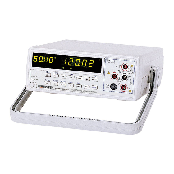
DUAL DISPLAY DIGITAL
MULTIMETER
MODEL: GDM-8246
User Manual
Good Will Instrument Co., Ltd.
GW Part No. 82DM-82460MA
Printed in Taiwan October 2002
All Rights Reserved
This manual contains proprietary information, which is protected by
copyrights. All rights are reserved. No part of this manual may be
photocopied, reproduced or translated to another language without prior
written consent of Good Will company.
The information in this manual was correct at the time of printing.
However, Good Will continues to improve products and reserves the
rights to change specification, equipment, and maintenance procedures at
any time without notice.
Good Will Instrument Co., Ltd.
No. 95-11, Pao-Chung Road, Hsin-Tien City, Taipei Hsien, Taiwan
Advertisement

Related Manuals for GW Instek GDM-8246


Summary of Contents for GW Instek GDM-8246
- Page 1 DUAL DISPLAY DIGITAL MULTIMETER MODEL: GDM-8246 User Manual All Rights Reserved This manual contains proprietary information, which is protected by copyrights. All rights are reserved. No part of this manual may be photocopied, reproduced or translated to another language without prior written consent of Good Will company.
-
Page 2: Table Of Contents
No.69 Lushan Road, Suzhou New District Jiangsu, China. INTRODUCTION………………………………………………….. declares that the below mentioned products GDM-8246 SPECIFICATION………………………………………………….. are herewith confirmed to comply with the requirements set out in the Council Directive on the Approximation of the Law of Member States relating to OPERATION INSTRUCTION……………………………………. -
Page 3: Safety Summary
DUAL DISPLAY DIGITAL MULTIMETER DUAL DISPLAY DIGITAL MULTIMETER USER MANUAL USER MANUAL 1. SAFETY SUMMARY WARNING. Warning statements identify condition or Measuring Circuit Measuring circuits are subjected to working voltage and transient stresses practices that could result in injury or loss of life. from the circuit to which they are connected during measurement or test. - Page 4 DUAL DISPLAY DIGITAL MULTIMETER USER MANUAL FOR UNITED KINGDOM ONLY NOTE: This lead/appliance must only be wired by competent persons WARNING: THIS APPLIANCE MUST BE EARTHED IMPORTANT: The wires in this lead are coloured in accordance with the following code: Green/ Yellow: Earth Blue: Neutral...
-
Page 5: Introduction
DUAL DISPLAY DIGITAL MULTIMETER DUAL DISPLAY DIGITAL MULTIMETER USER MANUAL USER MANUAL The wire which is coloured Blue must be connected to the 2. INTRODUCTION terminal which is marked with the letter N or coloured Blue This is a portable, bench-type dual display digital multimeter with a or Black. -
Page 6: Specification
DUAL DISPLAY DIGITAL MULTIMETER DUAL DISPLAY DIGITAL MULTIMETER USER MANUAL USER MANUAL 3. SPECIFICATIONS 2. TRUE RMS AC, AC+DC VOLTAGE Accuracy between 2% of range and full range. The specifications are operated under the essential conditions as follows: 20Hz- 50Hz- 2kHz- 10kHz- 20kHz-... - Page 7 DUAL DISPLAY DIGITAL MULTIMETER DUAL DISPLAY DIGITAL MULTIMETER USER MANUAL USER MANUAL 4. FREQUENCY MEASUREMENT AT ACV RANGE 6. TRUE RMS AC OR AC+DC CURRENT RANGE FREQUENCY INPUT LEVEL (SINE WAVE) ACCURACY Accuracy Between 2% of range and full range. ≧1 RANGE 20Hz-45Hz...
- Page 8 DUAL DISPLAY DIGITAL MULTIMETER DUAL DISPLAY DIGITAL MULTIMETER USER MANUAL USER MANUAL 8. RESISTANCE 11. CONTINUITY BEEPER Description Built in buzzer sounds when conductance is less than 5 ohm. RANGE RESOLUTION ACCURACY Open Voltage 3 volts maximum. 500Ω 0.01Ω 0.1%+4 Protection 450V dc or peak ac continuous.
-
Page 9: Operation Instruction
4-5. Over-range indication An input is over-range if it exceeds the full scale of the selected range. GDM-8246 indicates an input is over-range by lighting the “—OL—” pattern on display. 4-6. No specification indication On AC+Hz measured mode, when an input is less sensitivity, the secondary display show “————”. - Page 10 DUAL DISPLAY DIGITAL MULTIMETER DUAL DISPLAY DIGITAL MULTIMETER USER MANUAL USER MANUAL 4-7. Interface Operation Figure 4-1 Front Panel This instrument equips RS-232 as standard device with a D-SUB 9 PIN SHELL on the rear panel. Besides, the instrument also provides a GPIB option device with a 24 PIN SHELL in blue.
-
Page 11: Measurement Tutorial
DUAL DISPLAY DIGITAL MULTIMETER DUAL DISPLAY DIGITAL MULTIMETER USER MANUAL USER MANUAL 5-3. Resistance, capacitance, continuity beeper measurements 5. MEASUREMENT TUTORIAL 1). Press the button to select function. 2). Press [▲]or[▼]to the desired range. Press [AUTO/MAN] button 5-1. Voltage measurements (DCV, ACV, DCmV, ACmV) to change manual or auto-ranging. - Page 12 DUAL DISPLAY DIGITAL MULTIMETER DUAL DISPLAY DIGITAL MULTIMETER USER MANUAL USER MANUAL For example, if [dBm] is pressed when measuring voltage in the max 5-7. AC+DC measurements mode, the maximum value is converted to dBm. To release the dBm The function can be selected only when voltage or current function is function, press [dBm] again.
- Page 13 DUAL DISPLAY DIGITAL MULTIMETER DUAL DISPLAY DIGITAL MULTIMETER USER MANUAL USER MANUAL 5-10. HOLD and AUTO HOLD measurements 1) Select the required function and range, set maximum or The HOLD mode can keep the measured value on the primary minimum value by pressing [SHIFT][SET] and [HI] or [LO] in display.
-
Page 14: Measurement Techniques
DUAL DISPLAY DIGITAL MULTIMETER DUAL DISPLAY DIGITAL MULTIMETER USER MANUAL USER MANUAL 6. MEASUREMENT TECHNIQUES Figure 6-1: Voltage Conversion 6-1. dBm measurement technique dBm is defined as above or below a 1mW reference. A voltage measurement is converted to dBm using the following formula: dBm=10*log (1000*voltage value /reference impedance.) - Page 15 DUAL DISPLAY DIGITAL MULTIMETER DUAL DISPLAY DIGITAL MULTIMETER USER MANUAL USER MANUAL Figure 6-2: Crest Factor 6-3. AC+DC measurement A signal includes an ac component and a dc level. The relationship between the total rms value of the signal and the ac component and the dc component is: rms total= component...
-
Page 16: Maintenance
DUAL DISPLAY DIGITAL MULTIMETER DUAL DISPLAY DIGITAL MULTIMETER USER MANUAL USER MANUAL 7. MAINTENANCE 7-3. Line voltage conversion The primary winding of the power transformer is tapped to permit The following instructions are executed by qualified personnel only. operation from 100/120V, or 220/230V AC 50/60Hz line voltage. To avoid electrical shock, do not perform any servicing other than the Conversion from one line voltage to another is done by changing the operating instructions unless you are qualified to do so.
Need help?
Do you have a question about the GDM-8246 and is the answer not in the manual?
Questions and answers