Table of Contents
Advertisement
Quick Links
Download this manual
See also:
User Manual
Advertisement
Table of Contents

Subscribe to Our Youtube Channel
Related Manuals for Planet NVR-401


Summary of Contents for Planet NVR-401
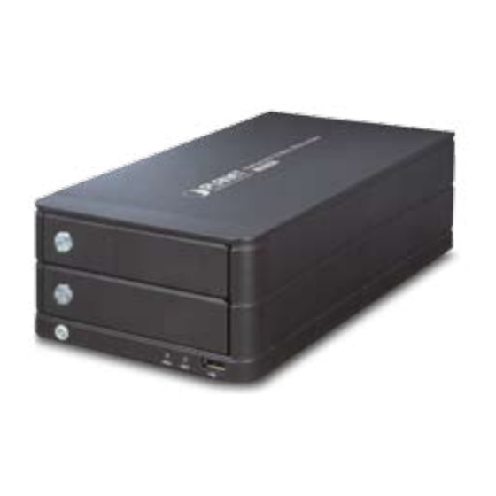
- Page 1 4-Channel Network Video Recorder NVR-401 User’s Manual Version 2.0...
- Page 2 "as is". Should the programs prove defective following their purchase, the buyer (and not PLANET, its distributor, or its dealer) assumes the entire cost of all necessary servicing, repair, and any incidental or consequential damages resulting from any defect in the software.
- Page 3 In the view of Saving the Energy and reduce the unnecessary power consuming, it is strongly suggested to switch off or remove the DC-plug for the device if this device is not intended to be active. Revision User’s Manual for PLANET 4-ch Network Video Recorder Model: NVR-401v2 Rev: 1.0 (November 2010)
-
Page 4: Table Of Contents
Table of Contents 1. Product Description ......................... 5 1.1 Product Features......................5 1.2 System Requirements..................... 6 1.3 Packet Content ....................... 6 1.4 Specification ........................7 1.5 Front / Rear Panel ......................8 1.6 LEDs Definition ......................8 1.7 Buttons ........................... 8 1.8 Connectors ........................ -
Page 5: Product Description
E-map interface in web Smart IP camera search Export record video file to AVI format Compliant with major brands. Axis, Panasonic, Sony, Planet, Canon and more Support mobile phone remote view with WinCE 6.1, Android, Symbian S60, iPhone, Blackberry 4.6... -
Page 6: System Requirements
1.2 System Requirements The following are minimum system requirements for the system to operate Network Video Recorder (NVR): Operating System Windows® XP Professional (32 bit), Windows® Server 2003 (32 bit), Windows Vista or Windows 7 Browser Microsoft Internet Explorer 7 or above Minimum Intel®... -
Page 7: Specification
1.4 Specification Product NVR-401 General Embedded Linux Ethernet 1 x RJ-45, 10/100/1000 Base-TX USB Interface 2 x USB2.0 for backup device and firmware upgrade 2 x 3.5” SATA hard disk Storage Device Max. Capacity: 3TB (1.5TB per HDD) Button Power, Reset... -
Page 8: Front / Rear Panel
1.5 Front / Rear Panel 1.6 LEDs Definition LEDs Color Description On: Power on. Power Blue Off: Power off. Blinking: HDD is accessing. Green Off: HDD is no action. 1.7 Buttons Button Description Power Press to start or shut down. Reset Press to reset NVR to factory default. -
Page 9: Connectors
1.8 Connectors Connector Description Connect your USB flash disk for firmware upgrade. DC Connector Connect the bundled power adapter. Ethernet Supports 10/100/1000Base-T interface. -
Page 10: Install Hard Disk
2. Install Hard Disk 1. Push the silver button to release the HDD tray. 2. Pull out the HDD tray. - Page 11 3. Place the HDD on the tray and secure the HDD with the screws at the bottom (as illustrate). 4. Push the tray back in the unit and press down the black bar to secure the tray. 5. Connect the bundled power adapter to the power connector on the rear panel.
-
Page 12: Connect To The Nvr
3. Connect to the NVR There are various ways you can connect to the NVR and below are the suggested methods for different network setup: The NVR is placed in a network with a DHCP server: Connect to the NVR by using “Device Search”... - Page 13 Please click “Next” to continue. Please click “Install” to start the installation.
- Page 14 Once the installation is complete, please check the “Finish”. Please go to Start => Programs => NVR => Search NVR to run the search tool. Then you will see the utility start search the network. The NVR should be located and its IP address should be displayed: Double-click on it and the program should automatically access the NVR’s web .administration page from your default browser.
- Page 15 You may change NVR’s IP address by click on the button highlighted below. You will be prompted for the NVR’s login information before proceeding to change device’s IP address. You may click on the button highlighted below to perform search again. Or double-click on any of the search results to access NVR’s web administration page.
-
Page 16: Access Nvr With Its Default Ip Address
3.2 Access NVR with its default IP address The NVR comes with a pre-configured static IP address “192.168.0.20”. However, it is only used when there is no DHCP server presented in the network. Connect the NVR and PC to your switch or hub, or connect the PC directly to the NVR using a crossover CAT.5 Ethernet cable. -
Page 17: Live View
4. Live View The NVR-401 comes with a 4-video split window view with one video displays on a larger window. Select a channel from the drop-down menu to display its video on the larger split window. You can also double-click on any of the smaller one to display its video to the larger window. -
Page 18: Retrieve Camera's Video Stream
4.1 Retrieve camera’s video stream The camera list is expanded and displayed on the Live View page. Click “All” to display videos in the 4-video mode. Click on any camera to display video in single-view mode. 4.2 Retrieve camera’s status The camera list can show each camera’s current status. -
Page 19: Ptz Control
4.4 PTZ Control PTZ control provides functions to pan, tilt, and zoom a PTZ camera as well as the ability to adjust camera focus and iris. Camera(s) that are currently being selected for live viewing will be listed in the PTZ drop-down menu. Simply select a camera then use the PTZ control panel to control the camera. -
Page 20: Perform Ptz Preset Viewing
4.5 Perform PTZ Preset Viewing There are three functions provided in the “Preset” section: Perform preset point viewing of a particular camera. Auto pan a particular camera. Perform preset point sequence viewing. Preset Point Viewing Start by selecting a PTZ camera from the drop-down list: It’s available PTZ preset points will be listed in the drop-down list shown below: Select a preset position from the drop-down list and click... - Page 21 Auto Pan Viewing Start by selecting a PTZ camera from the drop-down list: Use the Auto-Pan control buttons to pan right, left and stop auto pan. Auto-Pan * Certain cameras do not support bi-directional pan movements. Pan Left Use the “Auto-Pan” button for such cameras.
-
Page 22: Live Video Control Buttons
4.6 Live Video Control Buttons Each live video window comes with control buttons with functions described below: Take a snapshot of a live video. Turn on/off audio of a live video. Start/stop recording of a live video (manual recording). Audio post function. Full screen view of a live video Display video in its original ratio... - Page 23 Take a snapshot of a live video To take a snapshot of a live video, click the button and the snapshot of the video will be displayed in a pop up window shown like below. Right-click anywhere on the image and select “Save Image as” from the pull-down menu.
- Page 24 Full Screen View of a Live Video To view a video in full screen, click the button. To exit full screen video, double-click anywhere on the video. Turn On/Off Audio of a Live Video You can retrieve audio from a particular camera. Simply click the button to do so.
-
Page 25: Change Web Ui Display Language
4.7 Change Web UI Display Language You can change the web UI display language from the current login username link located at the upper-right hand corner. Click on the link opens up a new window which displays detail information about the user as well as a drop-down menu which lets you change the display language. -
Page 26: Playback
5. Playback Playback is a function that allows you to play one or more videos that were previously recorded by a chosen recording method or due to an event trigger. The NVR offers synchronized playback from up to 4 channels and various types of search methods are provided to help you find the footage you need quickly. - Page 27 Selected channels will be marked in red Select “Search by time chart” from the “Search Method” drop- down list and click “Go” to start the search: Results will then be displayed in a “Date/Channel” table and boxes marked in blue represent videos found in those dates:...
- Page 28 Click on any blue cell box should direct you to the hour/channel table if there were multiple videos recorded during that date: * Videos from other cameras that are recorded on the same date will also be displayed. * Move the mouse cursor on a particular cell box without clicking gives you a preview of the playback video n a small thumbnail.
- Page 29 Selected channels will be marked in red. Select “Search by event” from the “Search Method” drop-down list and click “Go” to start the search. Results will then be listed like what is shown below (displays the oldest record top down). Click on a particular result to start the playback. * You can click “Next Search”...
- Page 30 Play by specific time If you know when a recording was taken place, you may choose the “Play by start time” from the “Search Method” drop-down list. Then you will be prompted to enter a specific time and date for the recorded video.
-
Page 31: Export Playback Videos To Avi Files
5.2 Export Playback Videos to AVI Files User can export the recorded playback videos stored on NVR-401 to a local computer and save them in AVI file format. The files can then be played on the PC by a 3rd party media player such as VLC player or Windows Media player. - Page 32 Specify the starting and ending hours of the video by entering numbers in the text boxes. Hit the “Start” button to start exporting. The file will be automatically named and saved under the C:\ partition. You will be notified once the process is completed successfully The exported AVI file will be saved under the C partition.
-
Page 33: System Setup
6. System Setup 6.1 System Configurations The “System Configurations” page provides users options to setup the device quickly and properly. After properly configuring all settings in all the sub-pages, users should expect a fully working network video recorder that is ready to manage cameras on the network. -
Page 34: Time And Date
as a DHCP server, or leave it disabled if there is already a DHCP server in the network 4. Click Apply for the settings to take effect. The recorder can detect the presence of a DHCP server upon startup. It sets itself to use static IP address if there is no DHCP server currently presented in the network. -
Page 35: User Account
6.1.3 User Account The recorder can be accessed by multiple users simultaneously. You can add, remove, and edit users by using options provided in this page to keep user information organized. Each recorder comes with a built-in “admin” account with password “admin”. -
Page 36: Group Privilege
6.1.4 Group Privilege Group Privilege is where you can create multiple customized access policies for situations if you need the recorder to be accessed by users other than the administrator. You can do so by creating a group, and then remove access privileges for certain configuration pages or cameras. -
Page 37: Disk Setup
6.1.5 Disk Setup Once you install a hard disk to the recorder, you would need to initialize it so that it can be ready for recording. You can obtain basic information about the disk you installed in this page. To initialize it, simply click the “Format” button. You can also connect external USB thumb drive to the recorder for firmware upgrade. -
Page 38: Channel Configurations
6.2 Channel Configurations 6.2.1 Add a Camera The NVR provides two options for adding a new camera. Users have the option to let the recorder automatically find the cameras or it is possible to enter camera’s information and add it manually. Automatic Search: 1. - Page 39 2. After that, the search should begin and its status should be displayed. 3. Found cameras should be listed and simply select a camera from the list and press “Configure”. 4. Its corresponding information should be displayed in the “Camera Information”...
- Page 40 If cameras are marked with “*” in the search result, it means those cameras are already configured and connected to NVR. Add a camera manually Simply follow the instruction described above but instead of using the “Search” function, enter the camera’s IP address and credential in the “Camera Information”...
-
Page 41: Osd Settings
6.2.2 OSD Settings The OSD (On Screen Display) allows users to add informational text message and embed it onto the video. By default, this function is turned off. To add texts to one or more videos. 1. Select a camera you would like to add text to and choose “Display OSD”. 2. -
Page 42: Ptz Preset Settings
6.2.3 PTZ Preset Settings The recorder supports PTZ cameras and can set multiple preset points or retrieve and manage preset points that are set in the camera. This is helpful if you need to monitor multiple spots in one area from a particular camera. 1. -
Page 43: Ptz Preset Sequence
6.2.4 PTZ Preset Sequence Once you have multiple preset points defined for a camera, it is convenient for monitoring to set up the sequencing viewing among those preset point and let the recorder automatically switch between them for you. To configure preset sequence for a camera,” select a camera from the “Camera”... -
Page 44: Local Map Setting
6.2.5 Local Map Setting E-Map monitor is a function that alerts users whenever there is an event triggered (e.g. motion detected) from a camera with a geographical perspective. With this function, users can quickly identify which camera has detected an unusual event and where this event is happening. This function works by incorporating the event detection function as well as the recording function, which, as a result, helps users take all the necessary actions when an unusual event occurs. - Page 45 Then click and drag the camera icon to move the camera to define its location. Access the “Local MAP Monitor” page from the upper-right hand corner menu. When the NVR receives an event triggered from any of the cameras, their videos will be displayed on the E-Map and you can double-click on the video to enlarge it.
-
Page 46: Google Map Setting
Google Map monitor is an E-Map function that works like Local MAP. The difference is this function allow user to get the map from Internet Google map service. So you don’t have to provide a map to the NVR-401. In default, you will see the world map. - Page 47 Besides located by search address. You can also roll the central roller of your mouse to zoom-in/zoom-out the map to find out the address manually. Then click and drag the camera icon to move the camera to define its location. When the configuration finished, please press “Apply”...
-
Page 48: Event Configurations
6.3 Event Configurations The “Event Configurations” section allows users to define conditions that constitute an event, its corresponding trigger action and when it will be triggered. Such setting can reduce the management overhead and notify the administrator only when it’s necessary. 6.3.1 General Settings The general settings section can help you quickly configure when an event is triggered, how often events are triggered and the corresponding actions... -
Page 49: Di Settings
6.3.2 DI Settings This function allows users to manage camera’s digital input port right from the recorder. You can setup the recorder to receive triggers from a particular camera’s input port. 1. For cameras that come with physical digital input port, their port will be listed in the far left drop-down menu. -
Page 50: Event Servers
6.3.3 Event Servers Event servers are to be used with event trigger actions. In case of unusual motion detected by the camera or a disk failure, the recorder can send notification with the acceptable format (image/txt) to a destined event server according to the configuration. -
Page 51: Event Triggers
Configuring an SMTP server 1. Enter the hostname or the IP address of the SMTP server. 2. Enter the port of the SMTP server. 3. Specify the sender’s name in the “Sender’s name” field. 4. Enter the sender’s e-mail address. 5. - Page 52 Select Channels to Enable Event Trigger and which type of event should be triggered. Use the check box to enable event trigger on the desired channels. Define which system events should trigger the recorder to send out notifications Define how the notifications will be sent and where they will be sent to. * Event trigger may not work for cameras that are placed outside of your local network or on the Internet until the UPnP Port Forwarding”...
-
Page 53: Recording Configurations
6.4 Recording Configurations The “recording configurations” gives users the overall control of how and when a recording is performed and the quality of different types of recordings performed on each channels. It can help the recorder to operate with sufficient system resource by performing recording only when it’s necessary with adjustable recording frame rate. -
Page 54: Schedule Recording
Keep video allows you to set the NVR keep the record video in previous days. The section at the bottom allows you to turn on or off a particular recording type on any channels. You can check the box the enable NVR audio recording function. 6.4.2 Schedule Recording Here you can define the time range of the schedule recording for all channels. - Page 55 To configure a schedule recording: 1. Use the “Camera” drop-down menu and select a camera first. 2. You can use the schedule table to set the time range. Click the cell boxes then move the curser horizontally lets you set what hours to perform recording during a day.
-
Page 56: System Options
6.5 System Options System Options gives users a glance of the overall system status and allows users to perform maintenance tasks such as upgrading firmware, restore/backup device settings or reboot device ….etc. 6.5.1 Device Information The “Device Information” provides the general information of the device such as firmware version and system time. -
Page 57: Reboot The Nvr
Reboot the NVR Reboot NVR-401 after you upload a new firmware. You would need to manually reboot the system for the new firmware to take effect. Such process would prevent a recording from getting interrupted because the system would not automatically reboot itself after the new firmware is loaded onto the recorder. -
Page 58: Disk Status
Reset the NVR to Factory Default To reset the recorder back to its factory default, click “Default” button and begin the process. The process should be displayed and you should be prompted back to the “Maintenance” page after it is complete. 6.5.4 Disk Status “Disk Status”...
Need help?
Do you have a question about the NVR-401 and is the answer not in the manual?
Questions and answers