Table of Contents
Advertisement
Advertisement
Table of Contents

Related Manuals for Lynx DSX-1004


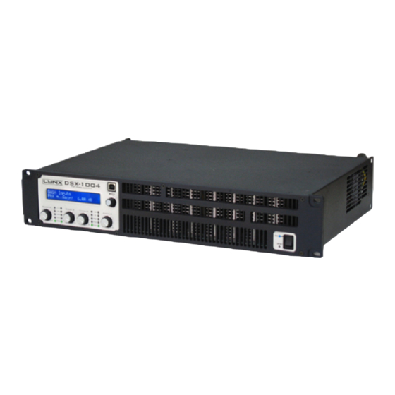
Summary of Contents for Lynx DSX-1004
-
Page 1: User Manual
USER MANUAL V.11.08 Valencia, Spain www.lynxproaudio.com... - Page 2 Calle 7 - Pol. Ind. Picassent E-46220 Picassent (Valencia) CE CERTIFICACTION, EUROPEAN PRODUCT RoHS Directive 2002/95/EC This user manual is property of Lynx Pro Audio S.L. Any reproduction of this manual, by any means is strictly prohibited. Copyright 2011. All rights reserved.
-
Page 3: Table Of Contents
1.- INTRODUCTION 1.1 Overview .....................5 1.2 Main Specifications..................5 2.- HARDWARE CONTROLS. 2.1 Front Panel ..................7 2.2 Rear Panel ..................8 3.- INSTALLATION AND OPERATION 3.1 Connections...................9 3.2 Configuration..................10 Protection systems..................11 3.4 Troubleshooting..................12 3.5 Software and usb drivers installation ..........13 Uninstall .................... - Page 4 INDEX Before starting to use the DSX amplifier, please read this instruction manual carefully. Keep these instructions in the place where the equipment will be used and with easy access to them. - Electrical appliance. The exclamation mark within a triangle identifies the presence of electricity. Use the system carefully without wet hands or feet.
-
Page 5: Overview
1 - INTRODUCTION 1.- Introduction 1.1 Overview The DSX Series Power Amps is our response to clients’ needs for a series of powerful, compact, versatile and rugged amplifiers characterised by no-compromises electronic and mechanical specifications. The DSX Series offers optional add-on modules that extend its operational capability to match any of today’s market requirements. -
Page 6: Technical Specifications
1 - INTRODUCTION Technical Specifications DSX-1004 DSX-4002 DSX-2800 DSX-2200 RMS power (8): 4 x 690 W 4 x 430 W 2 x 810 W 2 x 630 W RMS power(4): 4 x 975 W 4 x 670 W 2 x 1380 W 2 x 1100 W RMS power (2):... -
Page 7: Hardware Controls
2 - HARDWARE CONTROLS 2.- Hardware Controls 2.1 Front Panel See Figure A 1.- Signal attenuation level control knobs: Permit independent control of each channel.s attenuation (21steps). 2.- SIGNAL: This LED indicates presence of signal at the inputs. TEMP: This LED shows temperature protection is active. PMS: LED indicating PMS in operation. -
Page 8: Rear Panel
2 - HARDWARE CONTROLS 2.2 Rear Panel See Figure B 1.- Signal Input: Female Neutrik® XLR Connectors for the amplifier.s signal input. Signal Link: (2 channels models only) Male Neutrik® XLR Connectors for daisy chaining input signal to other amplifiers (parallel connected to female input connectors). 2.- Link / Dual Switch: in Link mode you can Link an Input to another adjacent input to use the same input signal. -
Page 9: Installation And Operation
3 - INSTALLATION 3. Installation and Operation 3.1 Connections The Power switch must always be on the .Off. position before plugging the amp to a properly earthed mains socket (220- 240V AC / 110V-120V AC). The input signal fed to the amplifier can be either balanced or un-balanced. The drawing below describes both ways to wire an XLR connector for the purpose. -
Page 10: Configuration
3 - INSTALLATION 3.2 Configuration The amplifier has an ensemble of minidips on the back panel, which allow for the following configurations: the highpass subsonic filter, the ICL deactivation and the bridge mode. All these configurations can be cross-set in any way, independently from the others. -
Page 11: Protection Systems
3 - INSTALLATION 3.3 Protection Systems ICL2™. - Intelligent Clip Limiter The ICL2 is an anticlip system to avoid speaker failure and provide more acceptable sound quality even when clipping occurs. With the ICL2 system you don’t lose the music .punch. but the speakers are kept under control. -
Page 12: Troubleshooting
3 - INSTALLATION CAUTION RISK OF ELECTRIC SHOCK DO NOT OPEN To avoid fire or electrocution risk do not expose the unit to rain or moisture. To avoid electric shock, do not open the unit. No user serviciable parts inside. In the case of disfunction, have the unit checked by qualified agents. Class I device. -
Page 13: Software And Usb Drivers Installation
3 - INSTALLATION 3.5.- Software and USB drivers installation. Before you install your copy of the DSX software, you must verify that your computer meets a series of minimum requirements to make it work. These requirements are: - Pentium IV or higher. - 512 Mb RAM memory. - Page 14 3 - INSTALLATION Start the installation by selecting the directory where the software will be installed. If you do not want to change it, it will be installed in the default directory, click with the mouse on the Browse button, and another window appears in which you pick where you want to install the Software.
- Page 15 3 - INSTALLATION Now the drivers installation screen will appear. Once the drivers has being installed on your PC, the program will inform you of the status of the installation. Then the next screen will report that the entire installation process has been done correctly. To complete the entire installation process of the software and drivers, the following window information appears, confirming that the process is correct and that we must restart the computer for the changes to be implemented.
- Page 16 3 - INSTALLATION TIPS: When connecting the processor for the first time, as in all peripherals that use USB, we leave a reasonable time for Windows™ to recognize the device and install the specified drivers. The first time you connect the amplifier DSX into a USB port, Windows will detect and install the device on the PC.
-
Page 17: Uninstall
3 - INSTALLATION 3.6.- Uninstall To uninstall DSX software you must follow the same steps common to any software. From the Control Panel Go to Add / Remove Software. Here select DSX and press the Add / Remove button ... We recommend making a backup of all configuration files created (with a. -
Page 18: Firmware Update
3 - INSTALLATION 3.8.- FIRMWARE Upgrade. We recommend using the USB port for such upgrades, for its reliability and speed, even when sometimes it can be more comfortable updating via the network connection. The firmware update is done automatically. The software contains the latest version of firmware. When establishing the connection, it checks the version of the processor firmware. - Page 19 3 - INSTALLATION First Step will be deleting the Flash memory to make it ready to write the new data. Once it is empty, write new Data will start. If the process is executed correctly, the next screen will appear:...
-
Page 20: Editing With Dsx Software
4 - EDITING WITH DSX 4.- Editing with DSX Software 4.1.- Main Screen. Upon entering in the DSX software, the main screen appears, which represents exactly the internal structure of processing. Here we can see the path that runs the audio signal from the inputs to the outputs in a very easy visual way, showing the different blocks and order of the signal flow. - Page 21 4 - EDITING WITH DSX Depending on the status of the connection, Real Time Button will look like: Offline Online Clicking on the red button we can choose between working in real time or not. We recommend that you make the whole configuration offline, save it into a memory, and then work on real time only to do the "final touch".
- Page 22 4 - EDITING WITH DSX Output configuration buttons. ROUTE: Clicking on this Icon you will be able to select from which of the inputs that channel will take the signal. Options are A, B, A+B, C, D and C+D (ARK 44 and 48) XOVER (Crossover).
-
Page 23: Editing In Offline Or Real Time Mode
4 - EDITING WITH DSX 4.2.- Editing in Offline or Real Time mode. Once you have some general information of the use of the mains windows, we can start working with the software. We can work with it in two options: in Offline Mode and in Real Time Mode. By default, software starts in Offline mode, which is the safest way to work on complete setups. -
Page 24: Additional Information
4 - EDITING WITH DSX 4.3.- Aditional Info. To begin with, and to avoid further oversights in the configurations that we make, we should take notes on each project, or sound equipment. We can do this by clicking the Additional Info Button. -
Page 25: Input Equalization (Parametric Or Graphic)
4 - EDITING WITH DSX 4.5.- Input EQ’s ( Graphic or Parametric) After Gain section you will find the input equalizer. Each Input has an equalizer of 29 filters selectable between graphic EQ or Parametric EQ. After pressing this button the next window appears, where you can give equalization to each main Input, and will look like: Parametric Option (PEQ): Current filter Open EQ file... -
Page 26: Signal Routing
4 - EDITING WITH DSX 4.6.- Signal Routing Already at Output section, the first button you will find is the ROUTE button. With Route buttons, you will be able to select from which input the signal will be taken through the channel Output. - Page 27 4 - EDITING WITH DSX The two columns represent the low cut (High Pass Filter) and higher cut (Low Pass Filter) in which you can configure crossover frequencies, the type of filter used for CrossOver and order of each filter to adjust the slope.
-
Page 28: Output Parametric Ecualization
4 - EDITING WITH DSX The ideal total electricity response will be in case of 4th+4th LinkWitz-Riley or 2nd+2nd with phase inverted on one of the channels. In other cases, you will be creating an enhancement of about 3dB for Butterworth and a ripple of approximately ±... - Page 29 4 - EDITING WITH DSX The frequency response is shown at the top. You will see the curves of the equalizer that is active in Show, each with the same colour as their respective indicator. You have 9 fully configurable filters on each Output.
- Page 30 4 - EDITING WITH DSX - Depending on the type of filter that you select, modifiable parameters will be activated, those will be: Frequency, Q (quality factor) and Gain. All the parameters are editable from the keyboard. The Frequency, Q and Gain can be directly changed by entering data on the keyboard and pressing enter. Q and Gain can also be edited through Arrow Up, Arrow Down.
- Page 31 4 - EDITING WITH DSX Shelving 6dB/oct f = 100,10000 G = 12, 6, -6, -12 Shelving 12dB/oct f = 100,10000 G = 12, 6, -6, -12 BandPass Q = 0.9,1.5,2.5,5,10,15,20 f = 1000 G = 12 StopBand Q = 0.9,1.5,2.5,5,10,15,20 f = 1000 LowPass Q Q = 0.3,0.5,0.8,1.5,2.5,5,10...
-
Page 32: Output Gain
4 - EDITING WITH DSX 4.9. - Output Gain From the Main screen, or from the Gain Levels window, you can adjust the levels of each output, also you can apply Mute, invert the polarity (Phase) or activate the Solo mode. By clicking on the "Link" boxes you can give the same parameters to other channels. -
Page 33: Output Delay
4 - EDITING WITH DSX You can adjust Output Gains for example: in order to get the right signal to each of the connected amplifiers, according to their own input sensitivity. And/or to compensate elctrically the diferent ways depending of the sensibility of the transducers in a multi way system, knowing that most of the times High and Mid frequencies needs an acoustical adjustment. - Page 34 4 - EDITING WITH DSX You also have the option of Temperature change, through which you can introduce the temperature (in Celsius or Fahrenheit) making the calculation of the speed of sound as accurate as possible. The calculation of the speed of sound (Vs) depending on the temperature is obtained with the following formula: Vs = 20.06 x (273+ºC) being ºC the temperature in Celsius degrees.
- Page 35 4 - EDITING WITH DSX For that we include the possibility of introducing the distances between elements on each output referring to a vertical plane. With these distances we can add the necessary delay to each channel, and visualize as the elements are lining up.
-
Page 36: Dynamics Configuration
4 - EDITING WITH DSX 4.11.- Dynamics configuration. The last section that we find on the Main window is the audio Dynamics, which consists of a block of RMS Dynamics and followed for another block of Peak limiter. Once the signal reaches this point there will be some parameters already applied, has Route selection, Gain, Crossover, Equalization and delay. -
Page 37: Rms Compression And Limitation, C.r.i Compression
4 - EDITING WITH DSX By clicking on buttons and sliders, you can access the configuration of each Dynamic, showing all the parameters (threshold, compression ratio, knee, Release time, etc.).. In the left chart it shows the dynamic curve that expresses the relationship between the level of input in dBu and output. If you do not want the dynamic active, you can press the button "Bypass"... - Page 38 4 - EDITING WITH DSX In the Compressor, the Output signal follows the Input signal if you are below the threshold. Once it exceeds, the output is mitigated depending on the chosen Ratio. In the next graphic there is a 1:2 ratio, which means that once the signal exceeds the threshold for every 2 dB increase in the input we will have 1 dB ...
- Page 39 4 - EDITING WITH DSX The third time we can configure is the HOLD. This would be the time that elapses between when we are below the Threshold until the Release enters. The adjustment of these parameters is very important and critical for the final sound quality. These speeds depend on the frequency range of the input signal.
- Page 40 4 - EDITING WITH DSX The graphic of the C.R.I. limiter shows a "normal" limiter of +4 dB compared with the C.R.I. limiters with +4 dB with a knee ± 2, 4, 6 and 8 decibels of action. There you can see that the dynamic control is becoming more progressive and we still have headroom even when the Limiter acts.
- Page 41 4 - EDITING WITH DSX CAUTION: LYNX PRO AUDIO S.L. IS NOT RESPONSIBLE FOR THE VERACITY AND ACCURACY OF THE DATA PROVIDED BY MANUFACTURERS IN TERMS OF ADMISIBLE POWER AND IMPEDANCE OF THE SPEAKERS, GAINS, SENSITIVITY AND POWER OF THE AMPLIFIERS. THEREFORE IT WILL NOT ACCEPT ANY RESPONSIBILITY FOR ADJUSTMENT OF THE LIMITERS THAT CAN DAMAGE EQUIPMENT, EXCEPT THOSE CONFIGURATIONS ON LYNX SYSTEMS.
- Page 42 4 - EDITING WITH DSX As in the screen of RMS Dynamics, if we do not want the Peak limiter to work, we can press the Bypass button to disable this action. Then the Peak Limiter screen shows a Bypass Active label To better understand how Peak limiter works, observe the following example, with the threshold values on -6 dB, 40 ms of Hold and Realease of 7 dB/s.
-
Page 43: Final Frequency Response
4 - EDITING WITH DSX 4.12.- Final Frequency Response. In the Main screen you will find this button : By pressing that button the Final Frequency Response will appear, where you can see in the same screen the cumulative effect of all process blocks such as the final response, PEQs (EQ), CrossOver (Xover), Gain and even the effect of Delays of inputs and outputs and the own electroacustic response, if we import measures from external softwares by clicking in Import Data. -
Page 44: Import Data
4 - EDITING WITH DSX In the right part of the screen we have the SHOW section, there we can activate the curves that we want to visualize. By activating ADD, it will be displayed on the screen (in black) the total frequency response, taking into account the magnitude and the phase of all ouptus that we have selected in this section. - Page 45 4 - EDITING WITH DSX Delete file Location of ASCII Open file explorer Measurement used files system Reference Level at 0 dB It is important to adjust the Reference Level to 0 dB. In this section we will introduce the average value that we believe that we have in the measurement files.
- Page 46 4 - EDITING WITH DSX CLIO: Perform MLS or Sinusoidal measure, preferably using 51,200 of sampling rate and a 1/6 octave smoothing for MLS and a resolution of at least 1/24 octave in the Sinusodial case. Once done, export as ASCII format pressing Shift + F2, which will generate a file with the name you want and extension *.txt that can be read by our software.
-
Page 47: Audio Precision
4 - EDITING WITH DSX AUDIO PRECISION: To import measure curves from AUDIO PRECISION ( *.ADX file extension) the Arkeops Software will ask for Frequency vs Magnitude file with the following format: C:\Apwin\S2\Frequency Response.at2, 10/25/07 12:14:18 Gen.Freq, Anlr.Bandpass, ,,,,,, Source 1, Data 1, ,,,,,, dBr A,... - Page 48 4 - EDITING WITH DSX WINAIR : Select MLS as analysis signal, and once you have the measure ready, one or an average of, go to "Storage" and "save as", put a name and it will be saved a *.txt file. The format should look like this: WinAIR saved file Samples per second 44100...
-
Page 49: Acoustilizer - General Considerations For Taking Measures
4 - EDITING WITH DSX General Considerations for taking Measurements. It is very important to take the measurements of the speakers correctly, so subsequent results are reliable and valid. The following list can be a useful guide to obtain good measurement data files. 1 - Take measurements of all the ways at the same distance (several meters) and with the microphone placed at the level that we consider as a central point of listening. - Page 50 4 - EDITING WITH DSX In the next graphics, it’s shown an adjustment example for the Mid and High ways in a real equipment using the transductors measures. First it’s shown only the measure of the natural response of the speakers in his box and with their corresponding Amplifier.
-
Page 51: Configuration
5 - CONFIGURATION 5.- Configuration 5.1.- Tools Menu. Once the parameters are in place for whatever configuration you need, it will be necesary to write on the processor memory what you saved on your computer hard disc, depending on the DSX model, so these will be ready to work just like you wish. - Page 52 5 - CONFIGURATION - Connect: When you press this button, you can choose to connect with the amplifier, via USB, a wrong connection will result in the software displaying a screen with an error message. - Read memory: This button allows you to read a stored configuration into the processor memories, use, edit or save it.
-
Page 53: Save And Open Configuration Files
5 - CONFIGURATION 5.2.- Save and Open Configuration Files. How to Save Configuration files. You can save at any time the current configuration by pressing in the Tools Menu The "Save Configuration" button. The files associated with DSX carry the extension *.d44 and *.d22, for amplifiers with 4 channels or 2 channels respectively, which must be respected so that we can re-open these settings. -
Page 54: Configuration Dsx
5 - CONFIGURATiON If you want to start a configuration from a blank project, and you have some active already, you will have to click on "New Configuration". The software will advise that all the parameters are going to be set to "0", losing any changes made. - Page 55 5 - CONFIGURACION We can also connect the processor via USB cable. This option is automatic, meaning it tries to connect directly when putting a USB cable, since it takes precedence over other types of connection. If the software cannot communicate with the processor, it will display the following error message: On the other hand, if you have more than one processor connected and you try to establish connection, the computer will connect to the first processor installed by Windows.
- Page 56 5 - CONFIGURATION Use the button Write to the Processor to save into the selected memory. While establishing connection Communications screen appears, showing Info of the status of the communication (initialization, checks, communications and end of this one) and the progress bar shows the percentage of the entire transmission. Once the transmission data is finished, the processor will move to that memory automatically, in order to start working in that one and "hear"...
-
Page 57: Security
5 - CONFIGURATION 5.4.- Security On many occasions you should block the access to the controls of the processor, avoiding undesired persons modifying the parameters, especially in fixed installations or when renting equipment and you do not want anyone to change any settings, like limiters for example. We have five security/blocking levels,plus one with password in every DSX model. - Page 58 5 - CONFIGURATION Once the password is activated, depending on the security level if we try to access a "blocked zone" the amplifier will ask for the password. If you do not enter it properly you will not be able to change anything. Even if you know the password, the security level will only allows you to change the settings that you was permited by this level.
-
Page 59: Updating Dsp Program
5 - CONFIGURATION 5.5.- Updating DSP Program As in all fields of computer science, evolution is constant. The DSX amplifier is a Live product in constant evolution. To ensure your DSX is always updated with the latest version of the DSP, you have the option to upgrade it through the Lynx website (www.lynxproaudio.com) you can download updates and improvements for your amplifier. -
Page 60: Declaration Of Conformity
DECLARATION OF CONFORMITY LYNX Pro Audio S.L. Calle 7 - Pol. Ind. Picassent E-46220 Picassent (Valencia) Lynx Pro Audio S.L. declares that DSX series (all models) are in conformity with the following EC directives: Low Voltage Directive 2006/95/EC Electromagnetic Compatibility EMC...
Need help?
Do you have a question about the DSX-1004 and is the answer not in the manual?
Questions and answers