
Related Manuals for Hubbell T


Summary of Contents for Hubbell T
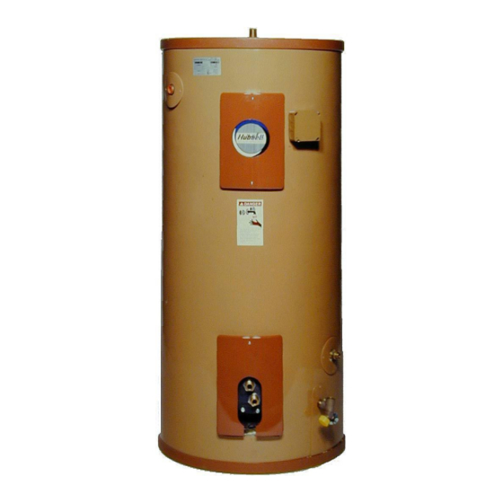
- Page 1 OPERATING AND MAINTENANCE MANUAL FOR COMMERCIAL INDIRECT POWERED WATER HEATER ELECTRIC HEATER COMPANY BASE MODEL “ T ”...
-
Page 2: Warning / Caution
A qualified installer is a person who has licensed training and a working knowledge of the applicable codes regulation, tools, equipment, and methods necessary for safe installation of an electric resistance water heater. If questions regarding installation arise, check your local plumbing and electrical inspectors for proper procedures and codes. -
Page 3: Table Of Contents
SECTION TITLE GENERAL DESCRIPTION AND CONSTRUCTION INSTALLATION SCHEDULED MAINTENANCE AND OPERATION TROUBLESHOOTING SERVICING AND REPLACEMENT OF PARTS MISCELLANEOUS CHARTS AND FORMULAS TABLE OF CONTENTS PAGE #... -
Page 5: Tank Connections
GENERAL DESCRIPTION AND CONSTRUCTION GENERAL DESCRIPTION This book describes a packaged boiler water powered indirect water heater that is a stationary, self- contained unit. The complete assembly on a standard unit consists of the storage tank, immersion heating coil, and an ASME rated combination temperature and pressure safety relief valve. Optional equipment may be supplied with your unit. -
Page 6: Control Thermostat
See drawing for voltage and power ratings. Control Thermostat The water heater may be supplied with either a surface mounted or immersion thermostatic switch to control the back-up electric heating system. See drawing for specific details. The surface mounted thermostat can be adjusted through a range of 110°... - Page 7 Temperature High Limit Switch As a safety device, either a surface mounted high temperature cut-off switch with manual reset, factory set at 190° F, or an immersion high temperature cut-off switch with manual reset, factory set at 180° F, may be provided. In the event of an over-temperature condition, the thermostat will disengage the power from the back-up electric heating system.
-
Page 8: Installation
For protection against excessive pressures and temperatures, local codes require the installation of a temperature-and-pressure (T&P) relief valve certified by a nationally recognized laboratory that maintains periodic inspection of production of listed equipment of materials, as meeting the requirements for Relief Valves and Automatic Gas Shutoff for Hot Water Supply Systems. -
Page 9: Piping Installation
PIPING INSTALLATION NOTE: The most effective means for preventing deterioration from accelerated corrosion due to galvanic and stray current is the installation of dielectric fittings/unions. The installation of these fittings is the responsibility of the installing contractor. 1. All integral components have been properly sized to meet design conditions. Piping to the unit should be sized to meet the design conditions, as dictated by good engineering practices. - Page 10 4. Install the combination temperature and pressure safety relief valve in the tapping provided. Note that this is required by law for safety considerations. Outlet to floor drain Manual Release Lever Temperature and Pressure Relief Valve 5. Install a relief valve overflow pipe to a nearby floor drain. CAUTION: No valve of any type should be installed between the relief valve and tank or in the drain line.
-
Page 11: Electrical Installation
1. Connect electrical wiring from boiler controls and circulator pump to immersion thermostat. 2. If supplied with a back-up electric heating element; enter electric enclosure with properly sized feeder leads. Be sure to properly ground the water heater. Install these power leads into the box lugs on the terminal block. -
Page 12: Quarterly Inspection
MAINTENANCE AND OPERATION The water heater is automatic in its operation. It will maintain a full tank of water at the temperature setting of the thermostat. The water heater should not be turned on without first making sure that the tank is full of water and that all air has been released. -
Page 13: Annual Inspection
ANNUAL INSPECTION 1. Flush tank as follows a. Shut off power supply. b. Close valve on hot water outlet piping. c. Open valve on drain piping. d. Cold water inlet line pressure will be strong enough to flush sediment from the bottom of the tank out through the drain. -
Page 14: Troubleshooting
SECTION IV – Symptom Gradual loss of heating capacity. Overheating. Immediate loss of heating capacity. Excessive vibration. Water hammer. * Red symptom indicates that equipment should be shut down immediately and cause of malfunction corrected before unit is re-started or serious damage may result. TROUBLESHOOTING Probable Cause Tubes are fouled. - Page 15 BACK-UP ELECTRCIAL HEATER SYSTEM (if supplied) Symptom No hot water Circuit breaker tripped at source. Reset circuit breaker. High limit switch tripped. Loose wires. Heating element inoperable. Low line voltage. Faulty thermostat. Water temperature Faulty thermostat. below settings at all times Heating element not working on all phases...
-
Page 16: Section V - Servicing & Replacement Of Parts
SECTION V - Before servicing or replacing any part make sure to turn the power supply switch to the OFF position. RELIEF VALVE 1. Disconnect power from unit. 2. Shut off incoming water and boiler water supply. 3. Lift test lever on relief valve to relieve pressure in tank. 4. - Page 17 HEATING COIL 1. Disconnect power from unit. 2. Shut off incoming cold and boiler water supply. 3. Attach hose to drain connection. 4. Lift manual release lever on relief valve to let air into system or break union on outgoing water line.
- Page 18 SURFACE TEMPERATURE HIGH LIMIT CUT-OFF (if supplied) 1. Disconnect power from unit. 2. Remove access cover. 3. Disconnect the four (4) 14 gauge wires or three (3) 14 gauge wires and a jumper, as required. Control Wires 4. Remove the two (2) mounting screws or disconnect from thermostat, as required. Mounting Screws 5.
- Page 19 IMMERSION TEMPERATURE HIGH LIMIT CUT-OFF (if supplied) 1. Disconnect power from unit. 2. Remove access cover. 3. Remove high limit cover screw and cover. 4. Disconnect the two (2) 14 gauge wires. 5. Remove capillary tube and bulb from thermowell 6.
- Page 20 HEATING ELEMENT (if supplied) 1. Disconnect power from unit. 2. Shut off incoming water supply. 3. Attach hose to drain connection. 4. Lift manual release lever on relief valve to let air into system or break union on outgoing water line. 5.
- Page 21 Single Element Operation 3 Ø Open Delta Wiring for Simultaneous Operation...
- Page 22 Interlocked for Non-Simultaneous Operation Non-Interlocked for Simultaneous Operation...
- Page 23 SURFACE MOUNTED THERMOSTAT (if supplied) 1. Disconnect power from unit. 2. Remove access cover and locate thermostat. 3. Disconnect the two (2) or three (3) 14 gauge wires and jumpers, as required. Control Wires 4. Remove two (2) mounting screws and disconnect from high limit cut-off, if required. Mounting Screws 5.
- Page 24 IMMERSION THERMOSTAT (if supplied) 1. Disconnect power from unit. 2. Remove access cover and locate thermostat. 3. Remove high limit cover screw and cover. 4. Disconnect the two (2) or three (3) 14 gauge wires, as required. 5. Remove capillary tube and bulb from thermowell.
-
Page 25: Miscellaneous Charts And Formulas
SECTION VI – MISCELLANEOUS CHARTS AND FORMULAS FORMULAS...
Need help?
Do you have a question about the T and is the answer not in the manual?
Questions and answers