Table of Contents
Advertisement
Quick Links
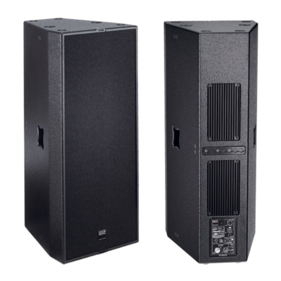
K&F LINE 212-6/-9
Die Version CA 106 F weicht in Form und Aussehen von
User's Manual
Benutzerhandbuch
Important Information,
Please Read before Use!
KLING & FREITAG GmbH
Junkersstrasse 14
D-30179 Hannover
PHONE +49 (0) 511- 96 99 70
TEL 0 (049) 511- 969 97-0
FAX
+49 (0) 511- 67 37 94
www.kling-freitag.de
dieser Abbildung ab.
Released: 08.09.2005
Stand: 08.06.2006
Version 5.0.
Version 1.0
Advertisement
Table of Contents


Need help?
Do you have a question about the LINE 212-6 and is the answer not in the manual?
Questions and answers