
Related Manuals for Vpon VP-408


Summary of Contents for Vpon VP-408
-
Page 1: User Manual
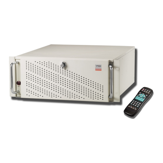
Network DVR System Your best choice for digital video recording and remote surveillance VP-408/412/416 User Manual (Version:V2.0) www.vpon21.com... -
Page 2: Important Information
When unpacking your VPON unit, check for missing or damaged items. If any item is missing, or if damage is evident, DO NOT INSTALL OR OPERATE THIS PRODUCT. Contact your dealer or us for assistance. -
Page 3: Table Of Contents
Contents 1. Overview 1.1 Introduction-------------------------------------------------------------------------------1 1.2 System requirements---------------------------------------------------------------------1 1.3 Features-------------------------------------------------------------------------------------1 1.4 Product specifications-------------------------------------------------------------------------------------2 1.5 Front panels --------------------------------------------------------------------------------------3 1.5.1 Back panels ----------------------------------------------------------------------------3 1.6 About the GUI-----------------------------------------------------------------------------------------4 1 . 6 . 1 T h e l o c a l GU I - - - - - - - - - - - - - - - - - - - - - - - - - - - - - - - - - - - - - - - - - - - - - - - - - - - - - - - - - - - - - - - - - - - 4 1.6.2 The network GUI-------------------------------------------------------------------4 2. - Page 4 3 . 1 5 . 5 T V o u t - - - - - - - - - - - - - - - - - - - - - - - - - - - - - - - - - - - - - - - - - - - - - - - - - - - - - - - - - - - - - - - - - - - - - - - - 2 3 3.15.6 OSD Text---------------- ------------------------------- -------------------------23 3 .
- Page 5 4. IR remote control operation 4.1 Introduction--------------------------------------------------------------------------------43 4.2 Main menu--------------------------------------------------------------------------------43 4.3 System setup------------------------------------------------------------------------------ 43 4.3.1 Password protect---------------------------------------------------------------------44 4.3.2 Video ( PTZ setup )-----------------------------------------------------------------45 4 . 3 . 3 Vi d e o i n p u t - - - - - - - - - - - - - - - - - - - - - - - - - - - - - - - - - - - - - - - - - - - - - - - - - - - - - - - - - - - - - - - - - 4 7 4.3.4 Disks---------------------------------------------------------------------------------47 4.3.5 TV output--------------------------------------------------------------------------- 48 4.3.6 OSD text---------------------------------------------------------------------------- 49...
- Page 6 4 . 6 . 2 S y s t e m l o g - - - - - - - - - - - - - - - - - - - - - - - - - - - - - - - - - - - - - - - - - - - - - - - - - - - - - - - - - - - - - - - - - - 6 7 4.6.3 Default settings-------------------------------------------------------------------68 4.6.4 Configuration file-------------------------------------------------------------------68 4.6.5 Revise firmware------------------------------------------------------------------68 4.7 System shutdown-----------------------------------------------------------------------68 5. VPON network operation 5.1 Introduction------------------------------------------------------------------------------69 5.2 Connecting-------------------------------------------------------------------------------69 5.3 Surveillance screen panel--------------------------------------------------------------70 5.4 Play button-------------------------------------------------------------------------------71 5.5 PTZ panel--------------------------------------------------------------------------------72...
- Page 7 6.1 Connecting to the network-------------------------------------------------------------84 6.2 Configuring Static IP Address---------------------------------------------------------84 6.3 Configuring Dynamic IP Address-----------------------------------------------------84 6.4 Finding the IP address of the VPON on the register server---------------------------------------------85 6.5 Using xDSL or cable Internet----------------------------------------------------------85 6.6 Using PPPoE---------------------------------------------------------------------------85 6.7 Using dial-up Internet----------------------------------------------------------------------------------------86 6.8 Remote access using dial-up-----------------------------------------------------------86...
-
Page 8: Overview
1.3 Features Video & audio live surveillance Plug and recording, VPON Network DVR Firmware in a DOM. Two-way audio transmission and multiple audio channels support. 1 / 4 / 6 / 7 / 8 / 9 / 10 / 13 / 16 split-screen display. -
Page 9: Product Specifications
Replaceable Graphic User Interface to meet OEM need. • Provides URL syntax for Web Page customization Support control morning software and POS /ATM solution 1.4 Product Specifications Model VP-408 VP-412 VP-416 Video Standard Support NTSC / PAL composite video, BNC video input Video Input... -
Page 10: Front Panels
1.5 Front panel Removable hard disks Reset switch Power switch Lock Cooling fans Handle 1.5.1 Back panel Printer port LAN port Video out ports Video in ports (VGA, S-video) (composite) Audio ports USB 2.0 ports COM ports USB 2.0 ports Keyboard and mouse Power input ports (PS/2) -
Page 11: About The Gui
1.6 About the GUI The VP-408/412/416 can be configured and operated using either the local GUI, or over a network. 1.6.1 The local GUI 1.6.2 The network GUI... -
Page 12: Getting Started
VP-408/412/416 using either mouse control, or IR remote controller(optional). Turn the VP-408/412/416 on using the power switch on the rear of the unit and the switch on the front panel. Front panel power switch Rear power switch The VP-408/412/416 will boot up in either IR control or mouse control running mode. -
Page 13: U D I
1. Click the SET UP button on the GUI to display the setup menu. 2. From the list on the left of the screen, click the Running Mode heading to display the running mode menu. 3. From the Control dropdown box, choose IR Control. 4. -
Page 14: Isp 5
2. Use the up and down arrow buttons to highlight the Running Mode option and press the OK button to confirm your choice. The running mode menu will be displayed on screen. 3. Use the up and down arrow buttons to highlight the Control – IR Control field. 4. -
Page 15: Introduction
3. Graphic User Interface (GUI) 3.1 Introduction VP-408/412/416 can be configured using either the supplied remote control unit (or a keyboard) or a mouse. This chapter covers mouse operation. The VP-408/412/416 must be in GUI mode for mouse operation. Under GUI mode, keyboard is used ONLY for data entry. -
Page 16: Setup Video Quality
Double click mouse right button to switch back normal live video. 3.3 Setup Video Quality Use the video quality button to set all the video parameters for the cameras connected to the VP-408/412/416. 1. First, please change to single screen as following . Select camera... -
Page 17: I / O B U T T O
Saturation - adjusts the amount of color for the selected camera. Hue - adjusts the dominant color for the selected camera. Quality (All) - adjusts the video quality for all cameras. The default setting is 80. We recommend that you do not set this to 100 to avoid slow video transmission rate and using up too much hard disk space. 3.4 I/O button Click the “I/O”... -
Page 18: Play Button
PTZ panel PTZ panel: You can do preset and recall, zoom in/out, focus, iris control to current camera. Preset buttons- Save current camera position. You can save totally16 preset positions Recall buttons- Move the camera to the selected preset position. ZOOM buttons - adjust the zoom to provide a more closer or wider view of the subject. - Page 19 Watermark Calendar Function buttons Play buttons Split-screen buttons Recording data status information Lock file Back to live surveillance Function buttons: Bookmark Alarm log Backing up the data Thumbnail Browse Search by Event Search by Text How to play recording file: Step3: Select camera to playback.
-
Page 20: Play Buttons
Date Color Meaning Have recording data White No recording data Square Today’s date Orange The day that was selected for playback Lock file: click the score bar under time line can lock file to keep the file not been erased by HDD cycle back writing Click to show normal recording status Click to show motion detection recording status... -
Page 21: Status Button
4. Status Button The status panel displays the playback status of the current recording. The aqua line (Data) indicates record data over an one hour time interval. The yellow bars (Motion) indicate the instance when motion was detected. The (GPI) indicate when a GPI event was detected. The moving orange line indicates current playback status. -
Page 22: Backing Up The Data
3.10 Backing up the recorded files If the DVR is equipped with CD/RW, DVD+RW drive, you can back up your recorded files to a CD, DVD, or USB hard drive. Note: The DVR will take some time to collect data before it can start back up process. 3.11 Thumbnail Browse Finds video images and selects them for processing individually, in whole folders, using a simple time selector and built-in image viewer .you can check out the results with the built-in viewer. -
Page 23: Search By Event
Back- Back to Thumbnail Browser window Ok - Start playback recorded file 3.12 Search by Event Searches the list of recorded files for the specified event such as a specific area of motion or a GPI Trigger that occurred within the specified time interval. Search by GPI Trigger: 1. - Page 24 Search by Motion: 1. Selection Rule – Select from one of Motion 1~16. All Time Range- Select “All Time Range”、”Today”、”Yesterday” or “User Define” for quicker searching. 2. Click “ok” to start search motion files in that specific time. 3. And then define search area . 4.
-
Page 25: Search By Text
3.13 Search by Text Searches recorded files that contain POS information of specified text. 1. After define POS text , select search starting time and camera . 2. Search results are as follow: Previous search result / Next search result / Search result list / repeat / Enable or disable pos data Note : Click the “search result list”... -
Page 26: Close Playback Screen
[ System setup] 3.15 Setup Click the Set Up button to show VP-408/412/416 configuration set up the menu. There are three parts to the Set Up menu - System Setup, Record Setup, Alarm and Motion Detection. This section explains each of the menu pages in turn. -
Page 27: Video ( Ptz Setup )
Enter new passwords for Admin and User in the corresponding fields. Set an auto lock time if required in the Auto lock after field. The auto lock function locks the system after a given time and a password is required to unlock it. Click Lock Now! to lock the system immediately. Note: If you do not have a keyboard connected to the system, you can use the on-screen keyboard to enter your passwords. - Page 28 Standard: sets the video signal format. Choose NTSC in the US, or PAL in Europe and most Asian countries. If you are not sure about this option, select Auto. VP-408/412/416 will detect the video standard automatically. Brightness: adjusts the amount of light or brightness for the selected camera according to your preference.
-
Page 29: Video Input
PTZ time out: The timeout value represents the time given to the cameras to respond to a command. PTZ ID: each camera can define different ID, please set correctly when you have up to 2 PTZ cameras in one system. Dimension: sets 320 x 240 or 640 x 480 resolution for each camera. -
Page 30: T V O U
Test button to test if the drive is working correctly. 3.15.5 TV output Use the TV Output menu to configure the video output for the VPON DVR. The VPON DVR can support standard VGA computer monitors or TV type screens. Set the device type, standard, outputs and other parameters. -
Page 31: G P I
To display the OSD text: 1. Select the desired camera from the Camera drop-down box. 2. Click the Enable field to display the text. 3. Adjust the position of the text display on the image using the X and Y parameters. A value of X=0 and Y=0 would result in the text appearing at the top left corner of the camera image. -
Page 32: T C P / I
3.15.8 TCP/IP Use the TCP/IP menu to enter TCP/IP address details for the VP-408/412/416. 3.15.9 Account Use the Account menu to set up an administrator name and password as well as the super user name and passwords. -
Page 33: Audio
3.15.11 Serial ports The RS232 serial ports (COM1 and COM2) are used to attach PTZ camera control cables, external modems, cash register or GPIO modules to the VPON DVR. Use the Serial Port menu to set parameters for the two serial ports. -
Page 34: Date/Time
There are no configurable fields on this page. Click OK or Cancel to leave the screen. 3.15.13 Date/Time Use the Date/Time menu to set the precise time and date on the system. You can also set the local time zone in the T.Zone field. 3.15.14 ISP If you are using dial-up access to the Internet, use the ISP menu to enter details of your Internet Service Provider. -
Page 35: Registry
The Registry menu enables you to set up the registry server for your device. If you are using a dynamic IP address for the VP-408/412/416, you can set up the device to post its IP address to the VPON registry server. -
Page 36: Algorithm
3.15.17 Algorithm H.263: frame size is small and suitable for Network surveillance. MPEG4: Video quality good and frame size small. JPEG: Video quality best but frame size big. 3.15.18 NTP setup Use the NTP Setup menu to enter details of the Network Time Protocol (NTP) server used to synchronize the time of the device with the network. - Page 37 After making the changes, click on the Test & Save button to verify that the server is operational. Click OK to save changes. 3.15.19 License information: 1. There are two ways to grant POS license. One is key-in license key; the other one is plug-in a key-pro. So if you plug-in a key-pro you don’t need to key in the license number again in the license setup menu.
-
Page 38: Network Neighbor
POS machine then POS text should show up with video. 3.15.20 Network Neighbor User can copy the recorded files of VP-408/412/416 to other PC through network neighbor. 1. Enable the Network Neighbor function. 2. After define the server name, workgroup and WINS server, user can find out the DVR recording files from Microsoft windows network neighbor. -
Page 39: System Log
3.15.21 System Log: Any operation will be written into system log include local operation and remote operation. User can search system log by specific time. 3.15.22 Alarm Log Any alarm will be written into alarm log including motion trigger、GPIO trigger、Disk error、Video loss 、POS event.…..etc. -
Page 40: Default Settings
Restore configuration data: 1. Select restore section and click a device, which is shown in the field. 2. Select one “*.bin” in the field 3. Click “Restore” button will pup-up a menu to ask you to over write data. Select “ok” to start to restore configuration data. -
Page 41: Revise Firmware
Click Restore Defaults?(Yes/No) to restore defaults. Click Cancel or No to retain the current settings. 3.15.25 Revise firmware Use the Revise Firmware menu to upgrade the VP-408/412/416 firmware. Click Revise Firmware?(Yes/No) to start the firmware upgrade process. Click Cancel or No to abort the attempt. -
Page 42: [Record Setup]
Use the keyboard or mouse (recommended) to select either Shutdown or Reboot. Click OK to perform the operation. Click Cancel or No to abandon. [ Record Setup] 3.16.1 DVR setup Use the DVR menu under the Record Setup tab to set the Digital Video Recorder parameters. Select either Auto Stop or Cyclic Recording. -
Page 43: Gpi Trigger
3.16.3 GPI Trigger Use the GPI Trigger menu under the Record Setup tab to enable recording video from specified cameras when triggered by an external alarm(GPI) connected to the system. For instance, you may want to record video from a camera installed at your front door when the door lock is opened. In this case, connected an alarm module (not provided ) to lock and set the front door camera to start recording. -
Page 44: Alarm Setup
A voice call message can be recorded using an internal or external microphone, and can be played back using an internal or external speaker. Up to 60 voice messages can be recorded and stored on the VP-408/412/416 and used for different alarm events. - Page 45 3. You can enter at most 20 POS events. Once the captured POS data contains one of the defined POS events, VPON triggers actions for the event. For example, you can enter VOID and NO SALE in the POS Event respectively.
-
Page 46: Gpi Alarm
3.17.2 GPI alarm Use the GPI Alarm menu under the Alarm tab to set what actions are taken when a GPI alarm is generated. You can set up the alarm through a message, a beep, a video popup, or E-mail. 3.17.3 Motion Alarm Use the Motion Alarm menu under the Alarm tab to set what actions are taken when a motion detection alarm is generated. -
Page 47: Disk Space Low
Use the keyboard or mouse (recommended) to select the required camera for video lost from the Camera drop-down box and complete all fields as described in GPI alarm. Click OK to save changes. 3.17.5 Disk space low Use the Disk Space Low menu under the Alarm tab to set what actions are taken when the disk space is insufficient to record data. -
Page 48: Pos Event
Use the keyboard or mouse (recommended) to complete all fields as described in GPI alarm. Click OK to save changes. 3.17.7 POS event Select the POS event function and start to sep up reaction when receiving the text data from POS machine. You can set up the alarm through a beep, a voice call, or E-mail. - Page 49 Motion Detection Setup Procedure 1. Camera: Select the camera for setting motion detection. 2. Enable (Yes/No): Turn On/Off the motion detection. 3. Sensitivity: Select motion sensitivity level. 4. Directly drag the square on the screen to a desired & location for Motion Detection. Each small square on the displayed grid can be set to detect motion.
-
Page 50: Ir Remote Control Operation 4.1 Introduction
4.3 System setup The System Setup menu enables you to change many different parameters of the VP-408/412/416. This section describes each option in the System Setup menu. Use the Up and Down arrow buttons to highlight an option, and use the OK button to confirm your... -
Page 51: Password Protect
Use the Password Protect option to enable password protection, set administrator and user passwords, set the auto lock period and lock the system immediately. Enabling password protection prevents unwanted users from accessing or configuring the VP-408/412/416. The Password Protect menu has the following choices: Enable - enables password protection. - Page 52 4.3.2 Video Use the Video menu to set all the video parameters for the cameras connected to the VP-408/412/416. There is one video screen for each camera with the following parameters: Standard - sets the video signal format. Choose NTSC in the US, or PAL in Europe and most Asian countries.
- Page 53 Mirror Vertical – flips the video signal from the selected camera along the vertical axis. Max Connection - limits the maximum number of connections allowed to access the VP-408/412/416 over the Internet. Set to zero to allow the maximum number of connections.
-
Page 54: Disks
Normally, video input#1 is map to position #1. But you actually can set video inputs to any position from #1 - #16, (depends on how many VP-408/412/416 cards you install) on the screen as long as there is vacancy. -
Page 55: Tv Output
4.3.5 TV output The VP-408/412/416 can be connected to a VGA monitor or a TV to view the camera video signal. Use the TV Output menu to set the following parameters for the video output port: Device - sets the output to VGA or TV. -
Page 56: Osd Text
4.3.6 OSD text A line of text can be displayed with the video from each camera connected to the VP-408/412/416. Use the OSD Text menu to enable the text and alter it. You can also set the position of the text using the X and Y parameter values. -
Page 57: Tcp/Ip
Use the TCP/IP menu to set the IP address of the VP-408/412/416, the gateway, the subnet mask, the DNS server IP address, and the HTTP port. If you want to use the VP-408/412/416 on your network, see your network administrator to obtain a valid IP address for the VP-408/412/416. -
Page 58: Account
Note: It is important that you set up a user name and password. The user is different from the administrator and has access to only the video. Use the More Users function to alter the authorities of users who access the VP-408/412/416 from the Internet. To set an Admin/User name or password: Use the Up and Down arrow buttons to select the field to change. -
Page 59: Audio
4.3.9 Audio Use the Audio menu to set up the audio parameters for the VP-408/412/416. The configurable parameters areas follow: • Mic Gain – adjusts the gain of the microphone. • Speaker – adjusts the speaker output level (volume). -
Page 60: System Information
1. You can use the Prev Page and Next Page buttons on the remote control to toggle between the COM1 menu and COM2 menu. 2. When an optional GPIO module is connected to the serial port, the VP-408/412/416 detects it automatically and provides GPIO options in the system menu. -
Page 61: Alarm
4.3.13 Alarm Use the Alarm menu to define what constitutes an alarm condition and how the VP-408/412/416 reacts when such a condition occurs. You can configure an alarm condition to be generated when motion is detected by the camera, if the video signal is lost from a camera, if the disk space is too low, if there is a disk error or if pos event. -
Page 62: Video Popup
(such as a GPI or motion alarm, or video lost from a camera) occurs. You must install a voice/fax modem on one of VP-408/412/416 COM ports, configure the COM port as a voice Call/device, and make its protocol the same as that of the voice/fax modem for the voice call function to work. -
Page 63: Set Action ( Md/Video Lost/Disk Space Low/Disk Error/Pos )
Set Action Use the Set Action option to define what action is taken by the VP-408/412/416 when an event occurs. The following options are available: Video Lost - generates an alarm when the video from the selected camera is not available. -
Page 64: Isp
The Registry Server menu enables you to set up the registry server for your device. If you are using a dynamic IP address for the VP-408/412/416, you can set up the device to post its IP address to the VPON registry server. -
Page 65: Running Mode
4.3.17 Algorithm You can change the compression algorithm used by the VP-408/412/416 to record video. The VP-408/412/416 supports MPEG, JPEG, MJPEG, and H.263 ,MPEG4 algorithms for compression. For the JPEG and MJPEG algorithms, the video quality is better but the data rate is also high. The H.263 and MPEG4 algorithm provides a good video quality with low data rate . -
Page 66: License Setup
Level 3. Full functions – Can connect maximum 16 cash registers. 4.4 Record setup Use the Record Setup menu to set all the record options for the VP-408/412/416. There are four Record Setup submenus - DVR, Record Schedule, Motion Detection, GPI Trigger and Pre-Alarm. This section covers each submenu in turn. -
Page 67: Record Schedule
You can set an alarm to be generated when the hard disk is full and send notification through a beep, E-mail, or text message. To change the DVR mode: Select the Mode option from the DVR submenu using the Up and Down arrow buttons on the remote control. -
Page 68: Motion Detection
Use the Up and Down arrow buttons to select a field to change, from the following options: Enable -enables the recording schedule. Mon through Sun - enables recording on the specified days of week. Start Hour/Minute/Second - sets the exact time when the recording starts. Stop Hour/Minute/Second - sets the exact time when the recording ends. -
Page 69: Pre- Alarm
iii. Press the Cancel button to return to the previous menu when done. 6. Select the Save option and press the OK button to save all your changes. 7. Use the Prev Page and Next Page buttons to move to the motion detection menus for all connected cameras. -
Page 70: Playback
6. Press the OK button when the value is set correctly. 4.5 Playback Use the Playback function to display a list of all recordings stored on the VP-408/412/416. Use the Up and Down arrow buttons to select a recording to play back and press the OK button to confirm. The chosen track is played. - Page 71 Right/Left arrow buttons. Motion Detection – The yellow bars represent where motion detection was set off. Searching for a file: The VP-408/412/416 playback list can be searched for a specific file. You can conduct the search based on time, event, or text.
-
Page 72: Searching For A File
4.5.2 To search for a recorded file: While viewing the play list, press the Menu button to display the menu. Select one of the following options using the Up or Down arrow buttons: Search by Time - searches the list of recorded files for the specified recording time. Search by Event - searches the list of recorded files for the specified event such as a GPIO trigger that occurred within the specified time interval. -
Page 73: Backing Up The Data
Press the OK button to confirm. The VP-408/412/416 detects if there is a backup device connected to it and starts backing up data. Note: The VP-408/412/416 will begin to collect data as soon as the above screens are displayed. When the required data has been collected, the backup can begin. - Page 74 3. After selected one of the searching way, user can see the log and press “ok” button to enter submenu to get more detail information of log. 4.6.2 System log Any operation will be written into system log include local operation and remote operation. User can search system log by specific time.
-
Page 75: Default Settings
4.6.5 Revise firmware Use the Revise Firmware option to upgrade the firmware in the VP-408/412/416. The firmware can be revised through an external read-write CD drive, a USB flash drive, or a USB thumb drive. Connect the device to the VP-408/412/416 and then use this option. -
Page 76: Vpon Network Operation
Default User Name: webmonitor Default Password: oyo The first time you attempt to view the VP-408/412/416 user interface using a web browser, an ActiveX installation procedure will begin automatically. When the following window appears, click on the Download LVSETUP.EXE link. The download will begin and the following window will appear. -
Page 77: Surveillance Screen Panel
Click to complete the installation. The following message will appear. When installation is complete you will be able to view the VP-408/412/416 Home Page. The ActiveX installation is necessary only at first time. 5.3 Surveillance screen panel The Surveillance Screen Panel is very similar to the one on the local GUI. See Surveillance screen... -
Page 78: Play Button
There is no Sequence button on the network GUI. This feature is only available on the local GUI. 5.4 Play button Click the Play button to display a list of all the available recordings stored on the VP-408/412/416 in a new browser window. -
Page 79: Ptz Panel
From field To field Query button List all button Play file on this time button Click on a video recording to play it in a separate browser window. Play a recorded video from a specific time and date by entering the time and date in the From field and clicking Play file on this time. -
Page 80: System Information
Use the setup screen to change user definable parameters for the VP-408/412/416. Choose a submenu from the list on the left and click the link to display it. 5.6.1 System information Click the System Information link to display the System Information page. -
Page 81: Audio Setting
5.6.3 Audio setting Use the Audio setting menu to set parameters such as Mic Gain, Speaker, Mic Timeout and Speaker Timeout. You can also perform a self test to test if the microphone and speaker are working correctly. There are multiple audio inputs, user can define which audio mapping to which camera. “Audio1” is audio input from motherboard. -
Page 82: Set Ntp Server
5.6.7 Set serial ports The RS232 serial ports (COM1 and COM2) are used to attach PTZ camera control cables, external modems, or GPIO modules to the VP-408/412/416. Use the Serial Port menu to set parameters for the two serial ports. -
Page 83: Alarm And Remote Control
5.6.8 Set pos Use the Set POS page to set the color and front size for each of the connected cameras. Use the serial Ports menu to set the following parameters. Click the “Done” button to save the new settings. 5.6.9 Alarm and remote control GPI devices will show NC (normally closed) or NO (normally open) as the status of the switch. -
Page 84: Set Names And On-Screen Display
5.6.10 Set names and on-screen display Use the Set Names and On-Screen Display page to set names for the server and all cameras. You can also use this page to enter the text to be displayed on screen with each camera under the Set Overlay Text option. -
Page 85: Record Schedule
5.6.13 Record schedule Use the Record Schedule page to set up to 16 automatic recording schedules. For each record schedule, select the day, and start and stop times for recording. For each camera, select off, Normal Recording, Motion Detection Recording , GPI Trigger Recording or MD&GPI Trigger Recording to record only when motion is detected. -
Page 86: Gpi Trigger Recording
5.6.15 GPI Trigger Recording Use the GPI Trigger Recording to set up to 8 automatic GPI recording schedules. Clink the “Enable” item box to start the GPI Trigger, and then set the timetable for recording the Trigger. Click “Done” button to save the new setting. 5.6.16 Set Pre-Alarm The Set Pre-Alarm page on the network GUI enables you to set the number of frames that are recorded from each camera before a trigger is generated. -
Page 87: Search
The file plays back in the browser window with the status at the bottom. Specify the resolution in the Dimension field. Select the camera whose video you want to watch in the Camera field and select the number of cameras (1, 4, 9, or 16) in the Display field. Specify a high or low Bandwidth and click Download&Save to save the video recording to your local disk. -
Page 88: Send Mail
5.6.19 Send Mail The VP-408/412/416 can send a snapshot by E-mail when triggered by an alarm. Use the Send Mail page to set E-mail details for each camera. Under the Individual Settings, specific the type of event that cause the E-mail to be sent in the Type field by choosing Motion Detect or GPI. -
Page 89: Alarm Log
Under the Individual Settings, specify the type of event that causes the E-mail to be sent in the Type field by choosing Motion Detect or Continuous. Fill in the start and stop time for monitoring the alarm, the file name and directory for FTP. Enable a snapshot of the camera of video to be uploaded by selecting cameras in the Snapshot option. -
Page 90: Configuration File
User can backup or restore system configuration values to or from a file. 5.6.24 Back to home page The Back To Home Page link will redirect you back to the VP-408/412/416 home page. 5.6.25 View video without plug-ins You can view video even if the machine you are working on does not have the plug-ins necessary for video monitoring. -
Page 91: Advance Network Setting
6.1 Connecting to the network Note: To connect the VPON to an existing LAN, set up by using the supplied IrDA remote control first. Connect an Ethernet-capable computer to the VPON LAN port using an RJ-45 UTP cable or connect both of the PC and VPON to a same hub. -
Page 92: Finding The Ip Address Of The Vpon On The Register Server
6.4 Finding the IP address of the VPON on the registry server To find the IP address of the VPON when using DHCP, you need to search the registry server which the VPON is registered to. Use a computer connected to the internet and a standard browser. Enter the FQDN of the registry server into the browser to access the server. -
Page 93: Using Dial-Up Internet
LAN. If you are using a dynamic IP address, access the registry server, then search for your VPON. If you are using a static IP address, access that address to test if the LAN has been successfully set up. -
Page 94: Appendix A: Operation Via Local Keyboard
Appendix A: Operation via local keyboard To get VP-408/412/416 up and running via local keyboard, a keyboard is required. The interface of VP-408/412/416 operation is as following figure. 2~13 14 15 18 19 1. Esc: Cancel Provide cancel and close function. When pressing “Esc”, it will close current setting menu and returns to the previous level. -
Page 95: Appendix B: Irda Mode (Ir Remote Control)
Appendix B: IrDA mode (IR Remote Control) Users can operate VPON via IR remote control or local keyboard. There will be a OSD screen on the VGA monitor. Before operating VPON via IR remote control, please make sure that VPON has... - Page 96 N. Screen Display Change display mode to single or quad. The In turns button is not used for the VPON series. The IR remote control has four gray triangular buttons surrounding the OK button, resembling a baseball diamond. These are the primary buttons that you will be using the majority of the time.
-
Page 97: Appendix C: Guide To Revise Firmware Of Vpon
1. If you want to download and update the system firmware, please check with your distributor to verify eligibility. 2. Open Windows Internet Explorer and type in your VPON DVR IP address like this: “http://VPON IP/revise.htm” 3. Browse for the saved copy of the updated firmware and click revise program then start to the update process. -
Page 98: Appendix E: View Video By Pda Or Cell Phone
You can view video as following: Appendix F: NET I/O (optional) One VPON DVR can offer to connect sixteen cash registers. We provide two devices to connect DVR and cash registers .one of device is VP-204 (NET I/O device) for connecting one cash register, the other one device is VP-204Q (NET I/O device) for connecting four cash registers at the same time. - Page 99 Go to the system menu and select “Serial Port” function to set up interface. VPON detects NET I/O automatically and NET I/O will be displayed. Note: If you plug-in many NET I/O devices, you will see VP204-1, VP204-2…in the serial port menu screen then you can set it out separately.
-
Page 100: Appendix G: Troubleshooting
3.You can access the VP-408/412/416 on the intranet, but not on the Internet. • Verify your intranet is connected to the Internet. • Verify if a valid public IP is assigned to the VP-408/412/416 or a valid public IP is mapped to a valid local IP assigned to VP-408/412/416.
Need help?
Do you have a question about the VP-408 and is the answer not in the manual?
Questions and answers