
Subscribe to Our Youtube Channel
Related Manuals for Biamp 801i


Summary of Contents for Biamp 801i
- Page 1 801i Mic/Line Mixer Operation Manual Biamp Systems, 10074 S.W. Arctic Drive, Beaverton, Oregon 97005 U.S.A. (503) 641-7287 www.biamp.com an affiliate of Rauland Borg Corp.
- Page 2 print update October 18, 2004...
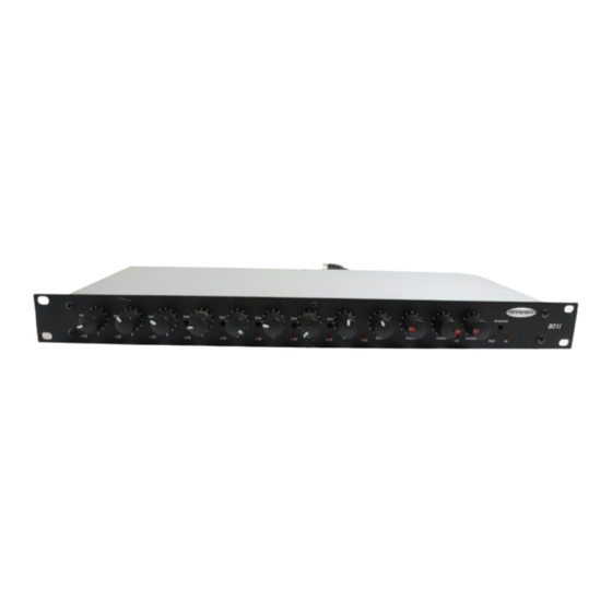
- Page 3 TABLE OF CONTENTS INTRODUCTION Front Panel pg. 2 The 801i is a single rack-space mixer, with eight mic/line inputs and one auxiliary line input. Each mic/line channel uses a differentially balanced, Rear Panel pg. 3 discrete transistor preamplifier for low noise and low distortion performance.
-
Page 4: Front Panel
Treble: This control provides high-frequency tonal adjustment (±10dB @ 10kHz) for signals at Main Patch & Main Output. On Indicator: When the power transformer is plugged in, and AC power is applied to the 801i, the red On indicator remains lit. -
Page 5: Rear Panel
Remote allows remote control of Main Output level, by enabling connect Main Output of one mixer to Stack In of the next mixer, the Remote terminals (see above). and so forth. All mixers except the final 801i should be assigned as ‘slaves’ (see Master DIP Switches below). For balanced DIP Switches (Channels 1~8 &... - Page 6 (0~+10VDC). An RP-L1 remote control panel is available as an option (see diagram below). Potentiometers are wired high (V), wiper (C), and low ( ). Ramp voltage is wired positive (C) and ground( ). The Remote port of the 801i mixer must be enabled before remote control of output level is possible (see Master DIP Switches on pg.
- Page 7 OPTIONS NOTE: The 801i chassis must be disassembled before installing input/output transformers: 1) remove plug-in barrier-strip connectors from rear panel. 2) remove top panel (2 screws at bottom of each side panel; 1 screw at top-center of front panel; 1 screw at top-center of rear panel).
- Page 8 SPECIFICATIONS & BLOCK DIAGRAM Frequency Response (20Hz~20kHz @ +4dBu): +0/-1dB Output Impedance: THD+Noise (20Hz~20kHz @ +4dBu): < 0.08% main output (balanced) 200 ohms Equivalent Input Noise (20Hz~20kHz, 150Ω term.): -123dBu channel direct (unbalanced) 100 ohms Output Noise (20Hz~20kHz): Maximum Output: master level control down <...
- Page 9 WARRANTY BIAMP SYSTEMS IS PLEASED TO EXTEND THE FOLLOWING 5-YEAR LIMITED WARRANTY TO THE ORIGINAL PURCHASER OF THE PROFESSIONAL SOUND EQUIPMENT DESCRIBED IN THIS MANUAL. BIAMP Systems expressly warrants this product to be 4. BIAMP SYSTEMS SHALL NOT IN ANY EVENT BE...
-
Page 10: Declaration Of Conformity
EN60065. The apparatus itself is outside of the scope of the LVD and presents no hazardous voltages, as defined in the LVD. For compliance, the apparatus shall be powered only from the separate CE marked BIAMP SYSTEMS power source. RF interference conducted through interconnect cabling may cause varying degrees of random signal degradation.
Need help?
Do you have a question about the 801i and is the answer not in the manual?
Questions and answers