
Related Manuals for Biamp VRAM


Summary of Contents for Biamp VRAM
- Page 1 VRAM Variable Resource Automixer Operation Manual Biamp Systems, 10074 S.W. Arctic Drive, Beaverton, Oregon 97005 U.S.A. (503) 641-7287 www.biamp.com an affiliate of Rauland Borg Corp.
- Page 2 blank print update September 7, 2005...
- Page 3 TABLE OF CONTENTS INTRODUCTION Front & Rear Panel Features pgs. 2 & 3 The VRAM Variable Resource Automixer is a 10-in / 2-out programmable automatic mixer, which is completely user tamper proof, providing no external Setup pgs. 4~9 controls. All mixer parameters are under microprocessor control, and are ®...
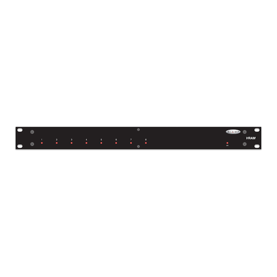
- Page 4 However, this may be an indication that the VRAM requires service. On Indicator: When AC power is applied to the VRAM, this red LED will light indicating power to the mixer is On. When power is Serial Port: This 9-pin Sub-D (male) connector provides an RS- removed, all ‘current mix’...
- Page 5 Main Out: This plug-in barrier strip provides the balanced Main Outputs from Channels 1~8 (see Logic Outputs on pg. 12). If a Out from the VRAM. For balanced output, wire high to (+), low to channel is assigned as ‘auto’ to either Main Out or Aux Out, the (-), and ground to ( ).
- Page 6 Once the software is started (and Comm Port Configuration is set), the control screens are accessed via the drop-down menus at the top of the opening screen. The Mix screen appears whenever a VRAM file is opened. Channel Settings, Automixer Settings, Button Definitions, Logic Input Definitions, Logic Output Polarity, &...
- Page 7 The Channel Settings screen appears as an overlay of the Mix screen, and is used to adjust individual input parameters. It is accessed via the Configure VRAM menu, or from the Mix screen. Individual tabs are provided for Channels 1~8 and the Aux Inputs. Right-clicking the blank area at the upper-left of a tab allows that input to be given a custom name.
- Page 8 The Automixer Settings screen is used to adjust automatic mixing functions, which affect the entire mixer. It is accessed via the Configure VRAM menu, or from the Mix screen. Channel Off Attenuation selects the amount of attenuation applied to ‘auto’ channels when they are inactive (gated off).
- Page 9 From the factory, Remote Control Buttons have equivalent ASCII characters permanently assigned to them (see RS-232 Control on pg. 14). Therefore, a Remote Control Button can be assigned specific ‘actions’, which the VRAM will then perform whenever the equivalent ASCII character for that button is received. From the factory, Remote Control Buttons have no pre- programmed functions.
- Page 10 Logic Input (or all Logic Inputs) to be cleared. Try It causes the actions currently assigned to the selected Logic Input to be performed by the VRAM. Help provides additional instruction. Close will close the Button Definitions screen.
- Page 11 Device Name allows a custom name to be given to the particular VRAM, by entering up to 30 characters of text. The Device Name will be stored in the VRAM memory, and will be displayed on the title bar of the Main screen whenever that VRAM is accessed with the software.
- Page 12 ‘low’ (less than +0.8 VDC), and is de-activated when its input goes ‘high’ (greater than +2.4 VDC). A Logic Input is controlled in one of three ways: 1) Use an NPN style ‘open-collector’ logic output from an external device (such as another BIAMP product) to short the Logic Input to ground.
- Page 13 LOGIC INPUTS Multiple contact-closures or ‘open-collector’ logic outputs may be wired in parallel to a single Logic Input (see diagram below). Logic Outputs and contact-closures should be rated for at least 5 Volts / 1mA operation. Low-current / dry-contact closures are recommended for reliability.
- Page 14 (reducing feedback problems). For example, if a speaker is located directly above microphone #1, the Logic Output for Channel 1 of the VRAM can be used to turn off that speaker relay when microphone #1 is active (see diagram on next page).
- Page 15 LOGIC OUTPUTS Logic/Relay circuit VRAM +12 Volts DC 12V Relay Power Supply − Pin #1 normally closed common Contacts normally open Logic Output #1 1N4004 Coil Diode Pin #9 Logic Outputs controlling indicators VRAM +12 Volts DC Indicator Panel Power Supply −...
- Page 16 RS-232 CONTROL The VRAM has an RS-232 Serial Port, which allows it to be controlled by a computer (see Front & Rear Panel Features on pg. 2). In addition to the BiampWin software, the VRAM offers two other methods of computer control.
- Page 17 Serial Port Data Communications Parameters: The VRAM communicates through the Serial Port at the factory selected rate of 38400 bits per second, with 8 data bits, 1 stop bit, and no parity. The VRAM utilizes a subset of the standard 7-bit ASCII character set. The eighth data bit of each character (the most significant bit) should always be 0.
- Page 18 SPECIFICATIONS & BLOCK DIAGRAM Frequency Response (20Hz~20kHz @ +4dBu): +0/-0.3dB Phantom Power: +36VDC (7mA/channel) THD + Noise (20Hz~20kHz @ +4dBu): < 0.03% Input Gain Range: Equivalent Input Noise (20Hz~20kHz, 60dB gain, 150 ohm): -126dBu mic/line inputs (variable trim) -6dB to +63dB Output Noise (20Hz~20kHz, main &...
- Page 19 WARRANTY BIAMP SYSTEMS IS PLEASED TO EXTEND THE FOLLOWING 5-YEAR LIMITED WARRANTY TO THE ORIGINAL PURCHASER OF THE PROFESSIONAL SOUND EQUIPMENT DESCRIBED IN THIS MANUAL 1. BIAMP Systems warrants to the original purchaser of new THIS WARRANTY IS IN LIEU OF ALL OTHER products that the product will be free from defects in material WARRANTIES, EXPRESS OR IMPLIED.
Need help?
Do you have a question about the VRAM and is the answer not in the manual?
Questions and answers