
Subscribe to Our Youtube Channel
Related Manuals for Biamp 301


Summary of Contents for Biamp 301
- Page 1 & Mic/Line Mixers Operation Manual Biamp Systems | 9300 S.W. Gemini Drive | Beaverton, OR | 97008 | USA | +1.503.641.7287 | www.biamp.com...
-
Page 2: Table Of Contents
301 & 601 TABLE OF CONTENTS Introduction pg. 1 Front Panel pg. 2 Rear Panel pg. 3 Remote Control pg. 4 Specifications & Block Diagram pg. 5 Warranty pg. 6 blank August, 2009... -
Page 3: Introduction
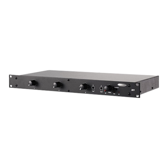
INTRODUCTION The 301 & 601 are single rack space, three input & six input mic/line mixers. Each input channel uses a differentially balanced, discrete transistor mic/line preamplifier for low noise and low distortion performance. Inputs are provided to accept signals from microphones and/or line level devices. -
Page 4: Front Panel
FRONT PANEL Trim: These screwdriver adjustable controls provide 40dB of gain adjustment to compensate for different input signal levels. For best performance, adjust Trim so the +10 Indicator flashes only on occasional peaks in signal level (see +10 Indicator below). +10 Indicator (Peak): These red LEDs indicate signal level in the channel has reached +10dB (8dB below clipping). -
Page 5: Rear Panel
(off) at the Main Out. Ch 3 / Ch 6 Duck switches: These DIP switches assign which input signals (Channels 1 & 2 on 301; Channels 1~5 on 601) will automatically trigger ducking (-15dB attenuation) on the last channel (Channel 3 on 301; Channel 6 on 601) for talk-over applications. -
Page 6: Remote Control
REMOTE CONTROL Remote Control: When using a slide potentiometer as a remote control, wire with High (T) to the voltage terminal (‘V’), Wiper (W) to the control terminal ("C"), and Low (B) to the ground terminal (‘ ’). When using a rotary potentiometer, wire with High (CW) to the voltage terminal ("V"), Wiper (W) to the control terminal ("C"), and Low (CCW) to the ground terminal ("... -
Page 7: Specifications & Block Diagram
SPECIFICATIONS & BLOCK DIAGRAM... -
Page 8: Warranty
WARRANTY BIAMP SYSTEMS IS PLEASED TO EXTEND THE FOLLOWING 5-YEAR LIMITED WARRANTY TO THE ORIGINAL PURCHASER OF THE PROFESSIONAL SOUND EQUIPMENT DESCRIBED IN THIS MANUAL 1. BIAMP Systems warrants to the original purchaser of new THIS WARRANTY IS IN LIEU OF ALL OTHER products that the product will be free from defects in material WARRANTIES, EXPRESS OR IMPLIED. -
Page 9: Ec Declaration Of Conformity
DIRECTIVES below except as noted herein. Any alterations to the product not agreed upon and directed by Biamp Systems Corporation will invalidate this declaration. Product Models: 301, 601, 801i...
Need help?
Do you have a question about the 301 and is the answer not in the manual?
Questions and answers