
Related Manuals for ESTeem 192C


Summary of Contents for ESTeem 192C
- Page 1 ESTEEM USERS MANUAL MODELS 192C/CHP/F/M/MHP Firmware Versions 1.51 and above September 2005 Electronic Systems Technology, Inc.
- Page 2 This manual and the firmware described in it are copyrighted by Electronic Systems Technology (EST), with all rights reserved. Under the copyright laws, this manual or the firmware internal to the ESTeem unit may not be copied, in whole or part, without the written consent of EST.
-
Page 3: Table Of Contents
Saving a Program Restoring Factory Defaults CHAPTER 2 – MODES OF OPERATION Command Mode Converse Mode Transparent Mode Semi-Transparent Mode Hardware Mode Control CHAPTER 3 – PROGRAMMING ESTEEM FEATURES Digi-Repeater Global Broadcast Auto Transmit Auto Connect Multi-Connect Remote Programming Security... - Page 4 Weather Proofing Coaxial Connectors Grounding Lightning Arrestors Reference Material Model 192C/F Outdoor Antenna Fixed Base Hardware Diagram Model 192CHP Outdoor Antenna Fixed Base Hardware Diagram Model 192M Outdoor Antenna Fixed Base Hardware Diagram Model 192MHP Outdoor Antenna Fixed Base Hardware Diagram...
-
Page 5: Before You Start
The following section will describe the installation and use of this valuable utility program. ESTEEM UTILITY The ESTeem Utility is designed to assist the ESTeem user in programming and troubleshooting. The Utility covers basic operation, programming, PLC applications, and diagnostics of the ESTeem. - Page 6 The power requirements for that product will be displayed. The ESTeem model AA174 power supply can be used with all ESTeem products. If you are using the ESTeem in a solar power application, press Calculate Solar Consumption button for the Amp/Hours required.
- Page 7 ENTER. Follow the instructions on the screen to establish a communication link between modems. 17. This second test will allow you to use the remote ESTeem as a digi-repeater for your local modem. This procedure is explained in the window and can test communication with only one computer.
-
Page 8: Basic Esteem Programming
HELP Functions Figure 10: Test Radio Communication The ESTeem has over eighty software commands to aid the user in their application. The HELP command allow the user to list the various software commands and their respective values. From the COMMAND mode, type HELP<cr>. Your display should list the following: Help switches are: (Lists all settings). -
Page 9: Saving A Program
Restoring Factory Defaults The ESTeem has a very simple procedure to restore the program variables in the unit to the factory default setting. When the FA<Enter> command is entered from the command mode the ESTeem will be configured from a variable table located in its EPROM. -
Page 10: Chapter 2 - Modes Of Operation
Example: CMD:ADD 15 <Enter> This enters the source address of the ESTeem to the decimal value of 15. The first three letters ADD were enough for the ESTeem to uniquely identify the command for ADDress. The number of characters that need to be typed varies depending upon the command being entered. -
Page 11: Transparent Mode
The TRANSPARENT Mode allows the ESTeem to pass all data characters (O-255 or 0-FF hex) using 8 data bits. To program the ESTeem in the TRANSPARENT mode the TRANSPARent command must be enabled and switch Bit 2 to ON (RS-232C Setup Switch). The TRANSPARent command will defeat the SENDPAC and COMMAND variables and put the ESTeem in the transparent mode when Bit 2 is ON. -
Page 12: Semi-Transparent Mode
COMMAND Mode to CONVERSE (or TRANSPARENT Mode) via a hardware control line. The hardware line is located on pin 19 of the RS-232C connector. If MODEC = ON, a "low or 0" on pin 19 (-3 to -15 vdc) will put the ESTeem in the COMMAND Mode and a "high or one"... -
Page 13: Chapter 3 - Programming Esteem Features
Any ESTeem in your radio network can function as a repeater for any other ESTeem. This is independent of the fact that the ESTeem being used as a repeater is linked or connected to another node, therefore an ESTeem can function as a repeater, operational node, or both at the same time. -
Page 14: Global Broadcast
SENDPAC (send packet) variable. The Auto Transmit feature is a timer that is enabled in the ESTeem that monitors traffic in and out of the RS-232C port. If there are characters in the RS-232C buffer, the termination control timer starts from the time the last receive or transmitted character is updated in the buffer. -
Page 15: Auto Connect
ESTEEM FEATURES AUTO CONNECT The Auto Connect feature allows the user to program the ESTeem to perform a CONNECT to another ESTeem when data is sent to the RS-232C communications port. To enable this feature perform the following from the COMMAND MODE: SETCON (1-255) = Address of destination ESTeem. -
Page 16: Multi-Connect
The first time around the pole a CONNECT data packet (RF transmission) will be initiated. When a link is established, it is held internally in the ESTeem connect table. The next time around the pole to the same address, the link status will be checked in the ESTeem table. -
Page 17: Remote Programming
The Remote Programming feature allows the user to remotely program ESTeems in his network. When a connection has been made with the remote ESTeem the RPG: prompt will be displayed showing that you are now in the COMMAND mode of that remote ESTeem. -
Page 18: Hardware Ring Line
The PACKM [ON/OFF] command places the ESTeem in a special packet monitor mode. When this feature is enabled the ESTeem is placed in a receive only mode and will not function as a normal ESTeem. The ESTeem will monitor and report the status of all message traffic within the network in the following format, the actual packet message will not be outputted. -
Page 19: Using The Infrared Communications Port
Note: With Switch 2 (RS-232 Setup) in the On position the ESTeem defaults the IR port to the command mode. The IR dongle has a range of approximately three feet, directly in front of the port. The dongle is powered by the serial port and requires no additional power sources. -
Page 20: Updating Flash Memory
UPDATING FLASH MEMORY The ESTeem Model 192 stores its operating system in flash memory that can be updated without returning the modem the to the factory. To upload the latest operating file, please contact Customer Support at 509-735-9092 or e-mail support@esteem.com to request the latest flash memory update file for your product. -
Page 21: Transparent Auto-Connect
Listed below are different application programs to aid the user in programming the ESTeem. TRANSPARENT AUTO-CONNECT This mode is used for a dedicated point to point application. The ESTeem will initiate the radio link when data is received by the RS-232/422/485 port. -
Page 22: Transparent Auto-Connect Global
This mode is usually used for a point to multi-point applications when a customers devices include their own addressing protocol to communicate between devices. The ESTeem packet addressing and acknowledge protocol is defeated. All ESTeems will receive the data transmission. The 32 bit CRC error checking on received data is still enabled. This program is used in all ESTeems , the only difference is the unit addresses. -
Page 23: Interactive Terminal Applications
EST has available complete Engineering Reports for each PLC manufacturer make which will be provided at no charge by calling EST Customer Support on 509-735-9092. All Engineering Reports are also available on the ESTeem Utility Resource Disk (EST P/N AA109) in Adobe™ PDF format. -
Page 24: Chapter 5 - Rs-232C/422/485 Interfacing
ESTeem RS-232C connector must be connected to the data input of the device you are connected to; otherwise, the ESTeem won't work. Likewise, the data input to pin 2 of the ESTeem must be connected to the data output of the device you are connected to. -
Page 25: Flow Control
ESTeem. The CTS signal on pin 5 is used to control the data into the ESTeem. When CTS is set (high on pin 5) the modem is ready to receive data. When CTS is reset (low on pin 5) the ESTeem is not ready to receive data. -
Page 26: Memory Buffers
RS-232C connector. The factory default setting is OFF. When this command is enabled the ESTeem will monitor the DTR signal on pin 20. If the DTR line being supplied to the ESTeem, from the user, is at a SPACE (high) condition then the ESTeem is enabled. -
Page 27: Rs-422/485 Configuration
RS-422/485 CONFIGURATION The ESTeem will support the requirements of the EIA Standard RS-422/485. This is a four (4) wire interface consisting of the TRANSMIT DATA (-), TRANSMIT DATA (+), RECEIVE DATA (-), AND RECEIVE DATA (+) or a two (2) wire interface using B (+) and A (-). - Page 28 RS-232C/422/485 COMRATE Tables The ESTeem Model 192 uses the COMRATE software command to set the communication port speed when Bit 1 on the RS-232 Setup Switches is in the ON position. The ESTeem Utility Program will calculate the required COMRATE value and download to the ESTeem in Step 3 of the Starting Out Menu or by selecting ESTeem Setup>Configure ESTeem Serial Port from the Terminal...
-
Page 29: Coaxial Cable
It is noted that a ¼ wave antenna that does not have ground plane radials requires a ground plane to operate at maximum efficiency. This can simply be a conducting surface under the antenna that is a ¼ wavelength in diameter. For the Model 192C (450-470 MHz) this is approximately 6.5 inches. -
Page 30: Grounding
Wrap the connector assembly with a non-adhesive silicone tape, EST part number AA243, for weather proofing (See Note 2). Ensuring to overlap onto the coax cable approximately 1 1/2 inches and follow the instructions on the ESTeem AA243 technical bulletin. - Page 31 CHAPTER 6 ANTENNA SETUPS Revised: 28 Apr 11 EST P/N AA104...
- Page 32 CHAPTER 6 ANTENNA SETUPS Revised: 28 Apr 11 EST P/N AA104...
- Page 33 CHAPTER 6 ANTENNA SETUPS Revised: 28 Apr 11 EST P/N AA104...
- Page 34 CHAPTER 6 ANTENNA SETUPS Revised: 28 Apr 11 EST P/N AA104...
- Page 35 CHAPTER 6 ANTENNA SETUPS Revised: 28 Apr 11 EST P/N AA104...
- Page 36 CHAPTER 6 ANTENNA SETUPS Revised: 28 Apr 11 EST P/N AA104...
- Page 37 CHAPTER 6 ANTENNA SETUPS Revised: 28 Apr 11 EST P/N AA104...
- Page 38 CHAPTER 6 ANTENNA SETUPS Revised: 28 Apr 11 6-10 EST P/N AA104...
- Page 39 Programming The ESTeem Model 192 For SWR Measurements Configure the hardware as per the above diagram. Turn Switch 2 on the RS-232 Setup Switch (located on the rear of the ESTeem) to the OFF position. Reset the ESTeem (front panel push button).
-
Page 40: Chapter 7 - Theory Of Operation
Once this packet of data is formed, it’s transmitted in a "burst," one ESTeem to another, hence the term "packet burst communications". Now, if more than one packet is required to send the data then the ESTeem goes into full automatic mode and transmits additional packets. -
Page 41: Spectrum Utilization
DATA PRIVACY Data privacy in the ESTeem is provided by three levels of data encoding in the firmware and by the user being able to define over four security and communications parameters (Unit Address, Network ID, and Operating Frequency) that allow communications access to the modem giving over 100 million combinations. -
Page 42: Effective Baud Rate
(ACK) from the destination modem before another packet is transmitted. All radio transmitters have a fixed delay time, this is the amount of time it takes the transmitter to stabilize once it is energized before it can send data. In the ESTeem the delay is approximately 15 milliseconds one way which includes transmitter turn-on time and packet frame overhead or a total turn around time accounting for the (ACK) of 30 milliseconds. -
Page 43: Appendix A - Fcc Information (Usa Only)
APPENDIX A FCC INFORMATION INFORMATION TO USERS WARNING: This equipment has been tested and found to comply with the limits for a Class A digital device, pursuant to Part 15 of the FCC Rules. These limits are designed to provide reasonable protection against harmful interference when the equipment is operated in a commercial environment. -
Page 44: Other Information
APPENDIX A FCC INFORMATION Other Information Model 192C Model 192M 25 KHz Channel Spacing, 19,200 bps 25 KHz Channel Spacing, 19,200 bps FCC Type Acceptance No: ENPESTEEM192 U.S.A. Type Acceptance: ENPESTEEM192M Emissions Designator: 17K6F1D Emission Designator: 17K6F1D 12.5 KHz Channel Spacing, 9,600 bps 12.5 KHz Channel Spacing, 9,600 bps... -
Page 45: Federal Communications Commission Field Offices
APPENDIX A FCC INFORMATION FEDERAL COMMUNICATIONS COMMISSION FIELD OFFICES ALASKA HAWAII NEW YORK 1011 E. Tudor Rd. 300 Almoana Blvd. 1307 Federal Building Rm 240 Box 2955 P.O. Box 50023 111 W. Huron Anchorage, AK 99510 Honolulu, HI Buffalo, NY 14202 CALIFORNIA ILLINOIS 201 Varick Street... -
Page 46: Appendix Bspecifications
APPENDIX B SPECIFICATIONS Model 192C/CHP/F/M Overall Specifications SWITCHES: DATA BUFFERS: POWER REQUIREMENTS: • • Models 192C & 192F CPU Reset Transmit 4000 bytes • • RS-232C/422/485 Setup Receive 4000 bytes • 10.8 to 16 VDC @ 400 ma Rx 2 W RF 1.5 A Tx... - Page 47 APPENDIX B SPECIFICATIONS Model 192C/CHP/F/M/MHP Overall Specifications ESTeem Model 192C ESTeem Model 192CHP Frequency Range 450 to 470 MHz 450 to 470 MHz Frequency Selection Digitally Synthesized - Software Selectable Digitally Synthesized - Software Selectable Frequency Stability +/- 1 ppm +/- 2.5 ppm...
- Page 48 APPENDIX B SPECIFICATIONS Model 192C/CHP/F/M/MHP Overall Specifications ESTeem Model 192F Frequency Range 400 to 420 MHz Frequency Selection Digitally Synthesized - Software Selectable Frequency Stability +/- 1 ppm Frequency Selectability 6.25KHz 19,200 bps @ 25 KHz Channel Spacing Canada: 2163 195 214A...
- Page 49 APPENDIX B SPECIFICATIONS Model 192C/CHP/F/M/MHP Overall Specifications ESTeem Model 192M ESTeem Model 192MHP Frequency Range 150 to 174 MHz 150 to 174 MHz Frequency Selection Digitally Synthesized - Software Selectable Digitally Synthesized - Software Selectable Frequency Stability +/- 2.5 ppm +/- 2.5 ppm...
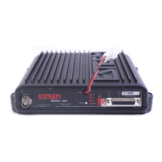
- Page 50 APPENDIX B SPECIFICATIONS Model 192C/CHP/F/M/MHP Case Diagram Revised: 13 Apr 05 APX B- 5 EST P/N AA104...
- Page 51 APPENDIX B SPECIFICATIONS Model 192C/CHP/F Antenna Specifications Model No: AA19C & AA19F Antenna Type: Omni-Directional, ½ Wave Applications: Mobile Mount. Frequency: 450 to 470 MHz - AA19C 400 to 420 MHz - AA19F Polarization: Vertical Impedance: 50 ohms Gain: 2 db.
- Page 52 APPENDIX B SPECIFICATIONS Model 192C/CHP/F Antenna Specifications Model No: AA202C & AA202F Antenna Type: Directional, DC grounded, 5 element yagi. Applications: Fixed base. Frequency: 450 to 470 MHz - AA202C 400 to 420 MHz - AA202F Polarization: Vertical or Horizontal...
- Page 53 APPENDIX B SPECIFICATIONS Model 192M/MHP Antenna Specifications Model No: AA19M Antenna Type: Omni-Directional, ½ Wave over ¼ Wave. Applications: Mobile Mount. 9.5 in. Whip Frequency: 150 to 174 MHz Polarization: Vertical Impedance: 50 ohms Drawing Not Gain: Unity To Scale 1 in.
- Page 54 APPENDIX B SPECIFICATIONS Model 192M/MHP Antenna Specifications Model: AA202M Antenna Type: Directional, 3 Element Yagi, DC Ground Applications: Fixed base mounting. Frequency: 150 to 174 MHz Polarization: Vertical or Horizontal Impedance: 50 ohms Gain: 7.1 dB VSWR: < 1.5 Front To Back Ratio: 17 dB Horizontal Beamwidth:72 degrees Model AA202M...
-
Page 55: Appendix C - Esteem Message Tables
ESTeem Command Error Messages Listed below are the ESTeem Command Error Messages and their definitions. To receive these messages, TYPSYSTEM must be ON (See Appendix D, Definitions). All System Status Message have a bell (O7H or CTRL G) preceding the message except when Messform is ON. - Page 56 ESTeem System Status Messages Listed below are the ESTeem System Status Messages and their definitions. To receive these messages, TYPSYSTEM must be ON (See APPENDIX D, DEFINITIONS). All System Status Messages have a bell (O7H or CTRL G) preceding the message except when Messform is ON.
- Page 57 ESTeem System Error Messages Listed below are the ESTeem System Error Messages and their definitions. To receive these messages, TYPSYSTEM must be ON (See APPENDIX D, DEFINITIONS). All System Status Messages have a bell (O7H or CTRL G) preceding the message except when Messform is ON.
-
Page 58: Software Commands
APPENDIX D SOFTWARE COMMANDS Listed below are the software commands and their factoy default setting. HELP CONTROL HELP SETUP HELP PLC APPENDRU = 255 ADDRESS A_BCTRL = OFF CONNECT COMMAND CUTLER = OFF CONVERS EDIT = ON = OFF DISCONNE MESSFORM = OFF GE_CTRL... - Page 59 This command is used in conjunction with the ROUTE Command. ASQuelch (0, 255) This command defines the squelch threshold of the receiver. This command is only used on the Model 192CHP. The ESTeem will auto adjust this setting. AUtolf (on/off) This command enables the auto line feed sent to the terminal after each carriage return.
- Page 60 On: Enabled Off: Disabled DArate (0 or 64) This command sets the RF data rate on the Model 192C/CHP/F/M products. This value is set at the factory and should not be changed. Factory default = 0. 0 = 19,200 bps...
- Page 61 If DTR is at a mark condition, then the ESTeem modem will be disabled. The normal operation of this line is for the ESTeem modem to have status on the external device, out-putting to pin 20. This line can act as a status to the ESTeem when the external device is ready to transmit or receive data.
- Page 62 APPENDIX D SOFTWARE COMMANDS GE_CTRL This command enables the General Electric controller protocol. For further information please reference the EST Engineering Report on General Electric controller interfacing. Enabled. OFF: Disabled. Factory default = OFF. HElp HELP switches are: HELP Displays this Help menu. HELP ALL Displays All commands switches and arguments.
- Page 63 Factory default = OFF. MOdecontr (on/off) The mode of the ESTeem modem is controlled by pin 19 of the RS-232C connector. A low (0) directs the ESTeem into the COMMAND mode. A high (1) directs the ESTeem into CONVERSE/TRANSPARENT mode.
- Page 64 APPENDIX D SOFTWARE COMMANDS MULTID (on/off) This command when enabled allows the ESTeem User to send data to another ESTeem from the CONVERSE MODE by specifying the routing address before the data. Enabled. OFF: Disabled. Factory default = OFF. Example Of Transmitted Data: [001]DATA Routes data to an ESTeem addressed 1.
- Page 65 POLLed (on/off) When enabled the ESTeem will only transmit the contents of its internal transmit buffer when it receives an ENQ (hex 5) from a polling ESTeem. During non polled times the ESTeem transmit buffer will be continuously updated from data being received by RS-232C/422 port.
- Page 66 Factory default = ON. RESet The software reset command for the ESTeem. The execution of this command resets the internal electronics in the ESTeem. RESTore The restore command. The execution of this command restores the ESTeem command variables and switches configurations stored in nonvolatile memory.
- Page 67 SECURITY (off or 1- 100000) The security command disables programming the ESTeem. 1 to 100000 This feature is enabled when you enter a number from 1 to 100000. When enabled the ESTeem will return a Security ON message. To disable security enter SECURity xxxxxx.
- Page 68 APPENDIX D SOFTWARE COMMANDS Serial Number command. When executed from the Command Model will output the ESTeem serial number of the unit that is defined at the time of manufacturer. SQDCTRL (on/off) This function enables the Square D controller protocol. For further detail Reference the EST Engineering Report on Square D controller interfacing.
- Page 69 This command enables the System and Error Message Commands. Enabled. OFF: Disabled. Factory default = ON. VERSION This command will display the current software version being used by the ESTeem. XHflow (on/off) This command enables hardware flow control. Enabled. OFF: Disabled.
Need help?
Do you have a question about the 192C and is the answer not in the manual?
Questions and answers