Table of Contents
Advertisement
Quick Links
BLOOMFIELD INDUSTRIES
2 ERIK CIRCLE, P. O. Box 280
Verdi, NV 89439
Customer Service (775) 345-0444 Ext.502
fax: (775) 345-0569
www.wellsbloomfield.com
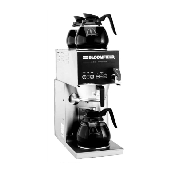
Model 1016BVM Brewer
with optional
8900-series glass decanters
75936
p/n
Rev. E ECN-12821
PRINTED IN UNITED STATES OF AMERICA
OWNERS MANUAL
for
E.B.C Electronic Brew
Control™
COFFEE BREWERS
MODEL:
1016BVM
Includes:
Installation
Operation
Use & Care
Servicing Instructions
This instruction is for the
exclusive use of licensees
and employees of
McDonalds Systems, Inc.
M912
912
05
0210 cps
Advertisement
Table of Contents

Subscribe to Our Youtube Channel
Related Manuals for Bloomfield 1016BVM


Summary of Contents for Bloomfield 1016BVM
- Page 1 Operation Use & Care Servicing Instructions This instruction is for the exclusive use of licensees and employees of McDonalds Systems, Inc. Model 1016BVM Brewer with optional 8900-series glass decanters PRINTED IN UNITED STATES OF AMERICA 75936 Rev. E ECN-12821 M912...
- Page 2 The prices charged by Bloomfield Industries for its products installation or eighteen (18) months from the date of shipment are based upon the limitations in this warranty.
-
Page 3: Table Of Contents
EXPLODED VIEW & PARTS LIST WIRING DIAGRAMS INTRODUCTION Thank You for purchasing this Bloomfield Industries coffee brewer. Proper installation, professional operation and consistent maintenance of this appliance will ensure that it gives you the very best performance and a long, economical service life. -
Page 4: Features & Operating Controls
1016BVM FEATURES AND OPERATING CONTROLS Fig. 1 1016BVM Features and Operating Controls... -
Page 5: Precautions & General Information
PRECAUTIONS AND GENERAL INFORMATION WARNING: Electric Shock Hazard All servicing requiring access to non-insulated components must be performed by qualified service personnel. Do not open any access panels which require the use of tools. Failure to heed this warning can result in electrical shock. WARNING: Injury Hazard All installation procedures must be performed by qualified personnel with full knowledge of all applicable electrical and plumbing codes. -
Page 6: Installation Instructions
90 PSI at anytime, a pressure regulator must be operation of the brewer. installed in the water supply line to limit the pressure to not more Bloomfield recommends 1/4" than 90 PSI in order to avoid damage to lines and solenoid. copper tubing for installation of A water shut-off valve should be installed on the incoming water less than 12 feet and 3/8"... - Page 7 IMPORTANT: Before connecting to electricity, make sure automatic brewers are connected to the water supply. Model 1016BVM is equipped with a cord and twist-lock plug. It requires a 120/240 volt 30 amp circuit (50/60 Hz, 3 wire plus ground, with NEMA L14-20R Twist-Lock Receptacle).
-
Page 8: Operation
1016BVM OPERATION Fig. 3 Brewer Operation Diagram IMPORTANT: A. START-UP Tank must be full of water For initial start-up, or if the brewer has not been used for an before pressing POWER extended period of time: key " ". Heating ♦... - Page 9 1016BVM OPERATION (continued) WATER HEATER Water temperature is sensed by an electronic water temperature probe inserted into the water tank. This temperature signal is fed to the controller. The setpoint temperature is adjustable. The controller sends a command signal to the...
- Page 10 OPERATION (continued) IMPORTANT: ELECTRONIC FEATURES DO NOT energize this brewer until the water tank Energizing the Brewer has been filled. Dry firing When electric power is applied to the unit, all the lights will flash four will damage heating times and four beeps will sound. The unit will be elements.
- Page 11 OPERATION (continued) Quality Timer Coffee looses its freshness as it sits on a warmer. The Quality Timer flashes the warmer lights 30 minutes after the last brew to remind you that the coffee is nearing the end of its useful life. After Hours™...
-
Page 12: Brewing Coffee
BREWING COFFEE CAUTION: A. PREPARATION Burn Hazard Place one (1) genuine Bloomfield paper filter in the Exposed surfaces of the brew chamber. brewer, brew chamber and decanter may be HOT to Add a pre-measured amount the touch, and can cause of fresh coffee grounds. -
Page 13: Cleaning Instructions
CLEANING INSTRUCTIONS CAUTION: PROCEDURE: Clean Coffee Brewer Burn Hazard PRECAUTIONS: Disconnect brewer from electric power. Allow brewer to cool. Brewing and serving temperatures of coffee are FREQUENCY: Daily extremely hot. Hot coffee will cause TOOLS: Mild Detergent, Clean Soft Cloth or Sponge serious skin burns. -
Page 14: Troubleshooting Suggestions
Repair/replace as needed Coffee level too high or low Timer out of adjustment Adjust controller. See page 16 Too many filter papers or wrong Use one (1) genuine Bloomfield filter paper filter per brew Brew chamber overflows Brew chamber dispense hole... -
Page 15: Error Detection
ERROR DETECTION The 1016BVM brewer is designed to perform a continuous internal CAUTION diagnosis, and to signal faults by flashing all the lights. In fault ELECTRIC SHOCK mode, warmers, heating element and water fill solenoid are turned HAZARD “off”, and most keypad functions are disabled. -
Page 16: Servicing Instructions
SERVICING INSTRUCTIONS CAUTION ACCESS PANELS Electric Shock TOP PANEL: Hazard Remove top panel to access hot water tank, thermo probe, Opening access panels or heating elements, brew circuit tubing, faucet valve and piping. removing warmer plates on this brew may expose uninsulated Top panel is held by two screws at the front and a retaining lip at the rear. - Page 17 SERVICING INSTRUCTIONS (continued) TEMPERATURE ADJUSTMENT CAUTION Electric Shock Unplug power cord or turn circuit breaker OFF. Remove top Hazard panel. Remove button plug from front panel These procedures involve exposed electrical circuits. These procedures are to be performed by qualified technical personnel only.
- Page 18 SERVICING INSTRUCTIONS (continued) BREW TIME ADJUSTMENT IMPORTANT: Water pressure must be between 20 p.s.i and The amount of water dispensed automatically during a brew cycle 90 p.s.i. flowing pressure. is controlled by the SOLENOID TIME dial of the controller. If water pressure exceeds this Place empty decanter under brew chamber.
- Page 19 SERVICING INSTRUCTIONS (continued) REPLACE SOLENOID Unplug power cord. Turn OFF and disconnect water supply from brewer inlet fitting. Remove front panel. Remove two screws holding access door in place. Remove access door and solenoid. Unscrew inlet fitting cap to release solenoid from door. Remove wiring from solenoid.
- Page 20 SERVICING INSTRUCTIONS (continued) RESET HI-LIMIT Allow brewer to cool. Remove front panel. Press red button on hi-limit until it clicks and stays in. Reassemble in reverse order. Test for function and proper operation. REPLACE CONTROLLER Unplug power cord OFF. Remove front panel. Remove timer faceplate. Use needle nose pliers to disengage three barbed fittings holding controller to bracket.
- Page 21 SERVICING INSTRUCTIONS (continued) SERVICING INSTRUCTIONS (continued) REPLACE POWER BOARD Unplug power cord or turn circuit breaker OFF. Shut off water supply valve. Remove front panel. Remove water tank lid (see page 16), then pull tank from cabinet to allow access to board. Note position of wires at power board, then remove wires.
- Page 22 SERVICING INSTRUCTIONS (continued) CAUTION - PROCEDURE: Delime the Water Tank CHEMICAL BURN HAZARD PRECAUTIONS: Disconnect brewer from electric power. Allow brewer to cool. Deliming chemicals are caustic. Wear appropriate protective FREQUENCY: As required (Brewer slow to heat) gloves and goggles during this procedure.
- Page 23 Should deliming hoses become necessary, 8. Reinstall wiring to heating element and thermostat. Bloomfield recommends Reassemble piping for the faucet. Verify that all internal replacing the hoses. components are dry, then reinstall the top panel.
-
Page 24: Exploded View & Parts List
EXPLODED VIEW & PARTS LIST (continued) - Page 25 EXPLODED VIEW & PARTS LIST (continued) ITEM PART # DESCRIPTION ITEM PART # DESCRIPTION 8540-4 ASSY TUBE FORMED NUT KEP 6-32 LG PATTERN ZI 8706-210 HOSE POLY-BRAID BUSHING HEYCO 1/2" 85752 SOLENOID 120V BYPASS .15GPM FITTING CONDUIT STRAIGHT 3/4 81732 ASSY LEG LEVELLING 8706-75 BUTTON PLUG 2"...
- Page 26 EXPLODED VIEW & PARTS LIST SERVICE KITS FAUCET REPAIR KITS 82573 Handle (item 12a) 82575 Seat Cup (item 12c) 82576 Faucet Repair Kit (Includes 12a Handle, 12c Seat Cup, 12d Spring, 12h Stem, 12j Pin & 12k Bonnet 82682 Retainer Clip (item 12b) 84804 Aerator Replacement Kit (Includes 12e O-Ring, 12f Aerator Disk &...
-
Page 27: Wiring Diagrams
1016BVM WIRING DIAGRAM... - Page 28 Bloomfield Industries proudly supports CFESA Commercial Food Equipment Service Association Prepared for Bloomfield Industries, Inc. Division of Carrier Commercial Refrigeration In US and Canada Telephone: 775-689-5700 Fax: 888-492-2783 Fax: 800-356-5142 ( for orders only website: www.wellsbloomfield.com PRINTED IN UNITED STATES OF AMERICA...
Need help?
Do you have a question about the 1016BVM and is the answer not in the manual?
Questions and answers