Table of Contents
Advertisement
Quick Links
WELLS BLOOMFIELD, LLC
2 ERIK CIRCLE, P. O. Box 280 Verdi, NV 89439
telephone: 775-689-5707
www.wellsbloomfield.com
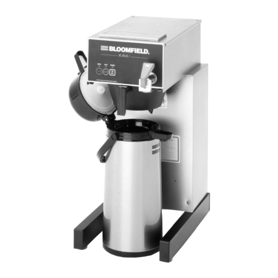
1088M
with optional
7759 Airpot
E.B.C.™ brewers are protected under
U. S. Patent # 5, 704,275
Other U. S. and Canadian patents pending.
77264
p/n
Rev.B ECN-13380
fax: 775-689-5976
PRINTED IN UNITED STATES OF AMERICA
Place this chapter in the Beverage
Section of the Equipment Manual
OWNERS MANUAL
for
E. B. C.™
Electronic Brew
Control ™
AIRPOT
COFFEE BREWER
MODEL:
1088M
Includes:
Installation
Use & Care
Servicing Instructions
This instruction is for the
exclusive use of licensees
and employees of
McDonalds Systems, Inc.
918
07
M918
1105 cps
Advertisement
Table of Contents

Related Manuals for Bloomfield 1088M


Summary of Contents for Bloomfield 1088M
- Page 1 WELLS BLOOMFIELD, LLC 2 ERIK CIRCLE, P. O. Box 280 Verdi, NV 89439 Place this chapter in the Beverage telephone: 775-689-5707 fax: 775-689-5976 Section of the Equipment Manual www.wellsbloomfield.com OWNERS MANUAL E. B. C.™ Electronic Brew Control ™ AIRPOT COFFEE BREWER...
-
Page 2: Warranty Statement
The prices charged by Bloomfield Industries for its products original installation or eighteen (18) months from the date of are based upon the limitations in this warranty. -
Page 3: Table Of Contents
WIRING DIAGRAMS SPECIFICATIONS AMPS POWER SUPPLY MODEL STYLE VOLTS WATTS 1ø CORD 1088 AIRPOT 115/230 3500 15.2 Requires 3 wire + gnd 3 WIRE cord not supplied APPLICABILITY This manual applies to the following Bloomfield products: 1088M... -
Page 4: Features & Operating Controls
FEATURES AND OPERATING CONTROLS Fig. 1 Features & Operating Controls... -
Page 5: Precautions & General Information
PRECAUTIONS AND GENERAL INFORMATION WARNING: ELECTRIC SHOCK HAZARD All servicing requiring access to non-insulated components must be performed by qualified service personnel. Do not open any access panels which require the use of tools. Failure to heed this warning can result in electrical shock. WARNING: INJURY HAZARD All installation procedures must be performed by qualified personnel with full knowledge of all... -
Page 6: Installation Instructions
A waterline filter is recommended in areas where water quality criteria to insure successful may cause taste and/or odor problems. operation of the brewer. Bloomfield recommends 1/4" copper tubing for installation of less than 25 feet and 3/8" for more than 25 feet from a 1/2"... - Page 7 IMPORTANT: The ground Model 1088M is equipped with a cord and twist-lock plug. prong of the plug is part of a It requires a 120/240 volt 20 amp circuit (50/60 Hz, 3 wire plus system designed to protect you ground, with NEMA L14-20R Twist-Lock Receptacle).
-
Page 8: Operation
OPERATION Fig. 4 Brewer Operation Diagram IMPORTANT: A. START-UP Tank must be full of water For initial start-up, or if the brewer has not been used for an before connecting brewer extended period of time: to electrical power. ♦ Be sure spray disk and brew gasket are properly installed in the Heating elements will be damaged if allowed to brew head. - Page 9 OPERATION (continued) WATER HEATER Water temperature is sensed by an electronic water temperature probe inserted into the water tank. This temperature signal is fed to the controller. The setpoint temperature is adjustable. The controller sends a command signal to the power board based upon a comparison between the setpoint temperature and actual temperature.
- Page 10 OPERATION (continued) IMPORTANT: ELECTRONIC FEATURES DO NOT energize this brewer until the water tank Energizing the Brewer has been filled. Dry firing When electric power is applied to the unit, all the lights will flash four will damage heating times and four beeps will sound. The unit will be elements.
- Page 11 OPERATION (continued) Quality Timer is normally Quality Timer set for 30 minutes. It can Coffee looses its freshness as it sits on a warmer. The Quality Timer be set for 20 minutes by flashes the warmer lights 30 minutes after the last brew to remind you moving a jumper on the controller.
-
Page 12: Brewing Coffee
BREWING COFFEE B. PREPARATION CAUTION BURN HAZARD Place one (1) genuine Bloomfield PAPER paper filter in the brew chamber. FILTER Exposed surfaces of the Add a pre-measured amount of brewer, brew chamber and fresh coffee grounds. airpot or server may be... -
Page 13: Cleaning Instructions
CLEANING INSTRUCTIONS PROCEDURE: Clean Coffee Brewer CAUTION BURN HAZARD PRECAUTIONS: Disconnect brewer from electric power. Allow brewer to cool. Brewing and serving temperatures of coffee are FREQUENCY: Daily extremely hot. Hot coffee will cause TOOLS: Mild Detergent, Clean Soft Cloth or Sponge serious skin burns. -
Page 14: Troubleshooting Suggestions
Coffee level too high or low Timer out of adjustment Adjust controller. See page 16 Brew chamber overflows Too many filter papers or wrong Use one (1) genuine Bloomfield filter paper filter per brew Brew chamber dispense hole Thoroughly clean brew chamber... - Page 15 ERROR DETECTION This brewer is designed to perform a continuous internal CAUTION diagnosis, and to signal faults by flashing all the lights. In fault ELECTRIC SHOCK mode, warmers, heating element and water fill solenoid are turned HAZARD “off”, and most keypad functions are disabled. Live electrical circuits may Error detection (all lights flashing) will occur under two conditions: be exposed while performing...
-
Page 16: Servicing Instructions
SERVICING INSTRUCTIONS CAUTION ACCESS PANELS SHOCK HAZARD TOP PANEL: Opening access panels or Remove top panel to access hot water tank, thermo probe, removing warmer plates on this heating elements, brew circuit tubing, faucet valve and piping. brew may expose uninsulated Top panel is held by two screws at the rear and a retaining lip at electrical components. - Page 17 SERVICING INSTRUCTIONS (continued) TEMPERATURE ADJUSTMENT CAUTION SHOCK HAZARD Place empty decanter under brew chamber. Energize brewer and allow unit to heat. When HEAT light goes out, press These procedures involve BREW key. Use a temperature probe with needle tip to read exposed electrical circuits.
- Page 18 SERVICING INSTRUCTIONS (continued) IMPORTANT: Water pressure BREW TIME ADJUSTMENT must be between 20 p.s.i and The amount of water dispensed automatically during a brew cycle 90 p.s.i. flowing pressure. is controlled by the SOLENOID TIME dial of the controller. If water pressure exceeds this value, or if water pressure Place empty decanter under brew chamber.
- Page 19 SERVICING INSTRUCTIONS (continued) REPLACE SOLENOID Unplug power cord. Turn OFF and disconnect water supply from brewer inlet fitting. Remove front panel. Remove two screws holding access door in place. Remove access door and solenoid. Unscrew inlet fitting cap to release solenoid from door. Remove wiring from solenoid.
- Page 20 SERVICING INSTRUCTIONS (continued) REPLACE HOT WATER FAUCET COIL IMPORTANT: When replacing water faucet coil, also replace (Symptom: Brewer drips continuously from brew head, except seal gaskets. when faucet valve is turned OFF.) Remove tank lid assembly per above. Remove two hex nuts hot water coil to cover. Pull coil from mounting holes.
- Page 21 SERVICING INSTRUCTIONS (continued) SET CONTROLLER JUMPERS Placing the jumper across Q1 sets Quality Time at 20 Minutes. Placing the jumper across Q2 sets Quality Time at 30 Minutes. Removing jumpers from both Q1 or Q2 disables Quality Timer. Placing the jumper across V1 sets Valve Time Range to - 180 seconds.
-
Page 22: Deliming Instructions
SERVICING INSTRUCTIONS (continued) CAUTION PROCEDURE: Delime the Water Tank CHEMICAL BURN PRECAUTIONS: Disconnect brewer from electric power. HAZARD Allow brewer to cool. Deliming chemicals are caustic. Wear appropriate protective FREQUENCY: As required (Brewer slow to heat) gloves and goggles during this procedure. - Page 23 Should deliming hoses become necessary, 8. Reinstall wiring to heating element and thermostat. Reinstall Bloomfield recommends the hi-limit thermostat (if removed). For automatic brewers, replacing the hoses. reassemble piping for the faucet. Verify that all internal components are dry, then reinstall the top panel.
-
Page 24: Exploded Views & Parts Lists
1088M EXPLODED VIEW & PARTS LIST HOT WATER TANK ASSEMBLY HOT WATER TANK ASSEMBLY ITEM PART NO. DESCRIPTION 8043-5 Hold Down Strap 8043-506 Nut, 8-32 SS Acorn 83644 Temperature Probe 8512-41 Seal Washer 8043-12 Tank Cover Gasket 8043-30 Seal Gasket... - Page 25 1088M EXPLODED VIEW & PARTS LIST (continued) ELECTRICAL COMPONENTS ITEM PART NO. DESCRIPTION 83763 Switch, Plug 1080-10 Keypad 8718-5 Cord & Cap Assembly 8552-18 Terminal Strip 35-210 Strain Relief 85753 Solenoid Valve (does not include quick-disconnect or inlet fitting) 83644...
- Page 26 1088M EXPLODED VIEW & PARTS LIST (continued) INTERNAL PLUMBING COMPONENTS ITEM PART NO. DESCRIPTION 8540-3 Faucet Outlet Tube Assembly 8540-4 Formed Inlet Tube Assembly 8572-26 Needle Valve (Faucet Shut-Off) Assy 85681 Inlet Tube Assembly Braided 8540-30 Elbow 8043-26 Tube Outlet Water 4-3/4 SS...
- Page 27 1088M EXPLODED VIEW & PARTS LIST (continued) CABINET COMPONENTS ITEM PART NO. DESCRIPTION 8543-42 Spray Head Gasket 82727 Spray Disk 8543-45 Spray Head Retainer 8706-75 Button Plug (Timer) Cap, Plastic, Lower Support Support, Lower 8033-55 Leveler, Adjustable Leg 8033-56 Cap, Adjustable Leg...
-
Page 28: Wiring Diagrams
1088M WIRING DIAGRAM MODEL VOLTS WATTS AMPS 1088M 115/230 3500 15.2...
Need help?
Do you have a question about the 1088M and is the answer not in the manual?
Questions and answers