ATEN VS172 User Manual
2/4 port dvi dual link splitter with audio
Hide thumbs
Also See for VS172:
- User manual (12 pages) ,
- Quick start manual (2 pages) ,
- Quick start manual (59 pages)
Table of Contents
Advertisement
Quick Links
Advertisement
Table of Contents

Related Manuals for ATEN VS172


Summary of Contents for ATEN VS172
- Page 1 2/4-Port DVI Dual Link Splitter with Audio VS172 / VS174 User Manual www.aten.com...
-
Page 2: Fcc Information
VS172 / VS174 User Manual FCC Information Warning: This is a class A product. In a domestic environment this product may cause radio interference in which case the user may be required to take adequate measures. FEDERAL COMMUNICATIONS COMMISSION INTERFERENCE... -
Page 3: User Information
VS172 / VS174 User Manual User Information Online Registration Be sure to register your product at our online support center: International http://eservice.aten.com Telephone Support For telephone support, call this number: International 886-2-8692-6959 China 86-10-5255-0110 Japan 81-3-5615-5811 Korea 82-2-467-6789 North America... -
Page 4: Package Contents
* Features may have been added to the VS172 / VS174 since this manual was printed. Please visit our website to download the most up-to-date version. -
Page 5: Table Of Contents
VS172 / VS174 User Manual Contents FCC Information ..........ii SJ/T 11364-2006. -
Page 6: About This Manual
VS172 / VS174 User Manual About this Manual This User Manual is provided to help you get the most from your VS172 / VS174 system. It covers all aspects of installation, configuration and operation. An overview of the information found in the manual is provided below. -
Page 7: Conventions
For information about all ATEN products and how they can help you connect without limits, visit ATEN on the Web or contact an ATEN Authorized Reseller. Visit ATEN on the Web for a list of locations and telephone numbers: International http://www.aten.com... - Page 8 VS172 / VS174 User Manual This Page Intentionally Left Blank viii...
-
Page 9: Introduction
EDID mode, mute the audio or upgrade the firmware version locally from one console. The VS172 / VS174 is easy to operate and can be cascaded to three levels and handle up to 8 (VS172) / 64 monitors (VS174), which makes them the ideal... -
Page 10: Features
RS-232 Chain Control – use RS-232 commands to control cascaded devices via a DVI cable EDID Expert – selects the optimum EDID settings via RS-232 Note: The VS172 / VS174 AP and GUI operation instructions can be downloaded from the ATEN website (www.aten.com). -
Page 11: Requirements
An audio out port (optional – for audio accompaniment to the display) Cables Two (VS172) or four (VS174) sets of DVI cable are required to properly operate this DVI Switch (not included). Note: 1. Cables are not included in this package. Since the quality of the display is affected by the quality and the length of the cables, we strongly recommend that you purchase high quality cables. -
Page 12: Components
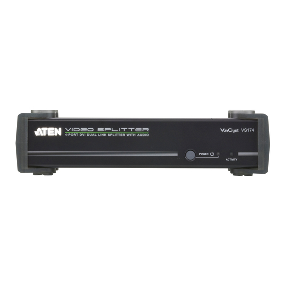
Use this button to turn on the unit or wake it from standby button mode. Power LED Lights green to indicate that the VS172 / VS174 is receiving power and is up and running. Lights orange to indicate that the VS172 / VS174 is in standby mode. -
Page 13: Rear View
1. Introduction Rear View VS172 VS174 Component Description Power Jack The power adapter cable plugs in here. A/V Input The cables from your source device’s DVI video and Section speaker ports plug in here. A/V Output The cables from your DVI monitors and speakers plug in Section here. - Page 14 VS172 / VS174 User Manual This Page Intentionally Left Blank...
-
Page 15: Hardware Setup
To prevent damage to your installation it is important that all devices are properly grounded. 1. Use a grounding wire to ground the VS172 / VS174 by connecting one end of the wire to the grounding terminal, and the other end of the wire to a suitable grounded object. -
Page 16: Single Stage Installation
VS172 / VS174’s Audio In port. 3. Plug your DVI monitors and speakers into the A/V Out ports. 4. (Optional) To edit the VS172 / VS174 system settings through the RS-232 port, connect the hardware / software controller here. -
Page 17: Cascading
To provide even more audio/video display, additional units can be cascaded from the VS172 / VS174’s A/V Out ports. Simply use additional male to male DVI and audio cables to connect an A/V Out port on the parent splitter to the A/V In port of the child splitter. - Page 18 VS172 / VS174 User Manual This Page Intentionally Left Blank...
-
Page 19: Operation
The 2/4-Port DVI Dual Link Splitter with Audio offers easy and flexible source device selection through the RS-232 serial interface. RS-232 Serial Interface The VS172 / VS174’s built-in bi-directional RS-232 serial interface allows system control through a high-end controller, such as a PC or home automation/home theater software. - Page 20 All output ports Control Description Turn on the VS172 / VS174 Turn off the VS172 / VS174 Note: Each command string can be separated with a space. The Port command string can be skipped and the default value will be used.
- Page 21 3. Operation Command for Cascaded Splitters Serial port commands for cascaded splitters require identifying the chain of ports to which the target device is connected. The formula for Switch Port commands are as follows: Switch Command + Output + Port + Port at first stage + Port at second stage + Control [Enter] First stage unit Second stage unit/s...
- Page 22 Extended Display Identification Data (EDID) is a data format that contains a display's basic information and is used to communicate with the video source/ system. You can set up which EDID mode the VS172 / VS174 uses with the following command:...
- Page 23 3. Operation Mute Commands Enable or disable audio coming from the output port(s) using the following command: Mute Command + Output + Port + Control [Enter] The following tables show the possible values and formats for the Output, Port and Control commands: Command Description mute...
- Page 24 The firmware upgrade command works only for the unit connected to the local PC or hardware / software controller. In order to upgrade the firmware of other VS172 / VS174 units in the cascade, manually connect them, one by one, to the local PC.
-
Page 25: Read Commands
Description Displays the status of the port Displays status of all ports Control Description version Displays the firmware version of the VS172 / VS174 edid Displays the EDID mode setting of device 01 video Displays the video status (on/off) audio Displays the audio status (on/off) Note: Each command string can be separated with a space. -
Page 26: Reset Commands
VS172 / VS174 User Manual Reset Commands Reset the VS172 / VS174 to default factory settings using the following command: Reset Command + Output + Port [Enter] The following tables show the possible values and formats for the Output and... -
Page 27: Appendix
Appendix Safety Instructions General Read all of these instructions. Save them for future reference. Follow all warnings and instructions marked on the device. Do not place the device on any unstable surface (cart, stand, table, etc.). If the device falls, serious damage will result. Do not use the device near water. - Page 28 VC1080 User Manual Never push objects of any kind into or through cabinet slots. They may touch dangerous voltage points or short out parts resulting in a risk of fire or electrical shock. Do not attempt to service the device yourself. Refer all servicing to qualified service personnel.
-
Page 29: Technical Support
Appendix Technical Support International For online technical support – including troubleshooting, documentation, and software updates: http://eservice.aten.com For telephone support, see Telephone Support, page iii: North America Email Support support@aten-usa.com Online Troubleshooting http://www.aten-usa.com/support Technical Documentation Support Software Updates Telephone Support 1-888-999-ATEN ext 4988 When you contact us, please have the following information ready beforehand: Product model number, serial number, and date of purchase. -
Page 30: Specifications
VC1080 User Manual Specifications Function VS172 VS174 Computer Connections Connectors Video In 1 x DVI-D female (White) Audio In 1 x Mini stereo jack (Green) RS-232 1 x DB-9 Female (Black) Video Out 2 x DVI-D F (White) 4 x DVI-D F (White)
Need help?
Do you have a question about the VS172 and is the answer not in the manual?
Questions and answers