Table of Contents
Advertisement
Advertisement
Table of Contents

Related Manuals for Bosch NTC-255-PI


Summary of Contents for Bosch NTC-255-PI
- Page 1 IP Camera 200 Series NTC-255-PI Installation and Operation Manual...
-
Page 3: Table Of Contents
3.7.1 Camera positioning Resetting the camera Browser connection System requirements Establishing the connection 4.2.1 Password protection in camera Protected network Connection established 4.4.1 LIVEPAGE 4.4.2 RECORDINGS 4.4.3 SETTINGS Bosch Security Systems Installation and Operation Manual AR18-10-B012 | v1.5 | 2011.01... -
Page 4: Table Of Contents
Picture Settings 6.4.2 Encoder Profile 6.4.3 Encoder Streams 6.4.4 Audio 6.4.5 Installer Menu Recording 6.5.1 Storage Management 6.5.2 Recording Profiles 6.5.3 Retention Time 6.5.4 Recording Scheduler 6.5.5 Recording Status AR18-10-B012 | v1.5 | 2011.01 Installation and Operation Manual Bosch Security Systems... -
Page 5: Ip Camera 200 Series Table Of Contents | En
System Log / Event Log 7.1.5 Saving snapshots 7.1.6 Recording video sequences 7.1.7 Running recording program Recordings page 7.2.1 Controlling playback Troubleshooting LED indicators Resolving problems Customer service Bosch Security Systems Installation and Operation Manual AR18-10-B012 | v1.5 | 2011.01... -
Page 6: En | Table Of Contents
| Table of Contents IP Camera 200 Series Maintenance Repairs 9.1.1 Transfer and disposal Technical Data 10.1 Specifications 10.1.1 Accessories AR18-10-B012 | v1.5 | 2011.01 Installation and Operation Manual Bosch Security Systems... -
Page 7: Safety
If not avoided, this could result in minor or moderate bodily injury. CAUTION! Low risk: Indicates a potentially hazardous situation. If not avoided, this could result in property damage or risk of damage to the device. Bosch Security Systems Installation and Operation Manual AR18-10-B012 | v1.5 | 2011.01... -
Page 8: Important Safety Instructions
10. Attachments, changes or modifications - Only use attachments/accessories specified by the manufacturer. Any change or modification of the equipment, not expressly approved by Bosch, could void the warranty or, in the case of an authorization agreement, authority to operate the equipment. -
Page 9: Fcc & Ices Compliance
Federal Communications Commission, helpful: How to Identify and Resolve Radio-TV Interference Problems. This booklet is available from the U.S. Government Printing Office, Washington, DC 20402, Stock No. 004-000-00345-4. Bosch Security Systems Installation and Operation Manual AR18-10-B012 | v1.5 | 2011.01... -
Page 10: Ul Certification
Please dispose of these devices at an environmentally compatible recycling facility, per European Directive 2002/96/EC More information For more information please contact the nearest Bosch Security Systems location or visit www.boschsecurity.com AR18-10-B012 | v1.5 | 2011.01 Installation and Operation Manual... -
Page 11: Copyrights
Digital Equipment Corporation not be used in advertising or publicity pertaining to distribution of the software without specific, written prior permission. This software is based in part on the work of the Independent JPEG Group. Bosch Security Systems Installation and Operation Manual AR18-10-B012 | v1.5 | 2011.01... - Page 12 | Safety IP Camera 200 Series AR18-10-B012 | v1.5 | 2011.01 Installation and Operation Manual Bosch Security Systems...
-
Page 13: Introduction
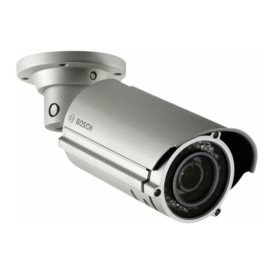
Introduction | en Introduction Features The Bosch NTC-255-PI infrared IP bullet camera is a ready-to- use, robust network camera. This camera offers a cost effective solution for a broad range of applications. The robust aluminum camera body is designed for outdoor surveillance or indoor areas where water ingress might occur. -
Page 14: Unpacking
– Installation paper sticker – Quick installation guide – CD ROM – Bosch Video Client – Documentation – Tools If equipment has been damaged during shipment, repack it in the original packaging and notify the shipping agent or supplier. WARNING! -
Page 15: Installation
Using the special screwdriver bit supplied, loosen the top adjustment screw (1) in the housing. Slide the sun hood (2) to the desired position. Tighten the top adjustment screw (1). Bosch Security Systems Installation and Operation Manual AR18-10-B012 | v1.5 | 2011.01... -
Page 16: Mounting
Attach the camera and base unit securly to the surface using the two supplied M4 screws. CAUTION! Do not point the camera/lens into direct sunlight as this may damage the sensors. AR18-10-B012 | v1.5 | 2011.01 Installation and Operation Manual Bosch Security Systems... -
Page 17: Network (And Power) Connector
Power can be supplied to the camera via the Ethernet cable compliant with the Power-over-Ethernet (IEEE 802.3af) standard. CAUTION! This equipment is only to be connected to PoE networks without routing to outside plant. Bosch Security Systems Installation and Operation Manual AR18-10-B012 | v1.5 | 2011.01... -
Page 18: Power Connection
Remove the 2-pole connector from the camera cable tree. Loosen the screws and insert the wires. Tighten the screws and reconnect the 2-pole connector to the power connector of the camera cable tree. AR18-10-B012 | v1.5 | 2011.01 Installation and Operation Manual Bosch Security Systems... -
Page 19: I/O Connector
Relay output switching capability: Max. voltage 24 VAC or 24 VDC. Max. 1 A continuous, 12 VA. – Relay in: Short or +5 VDC activation. – Alarm input configurable as active low or active high. Bosch Security Systems Installation and Operation Manual AR18-10-B012 | v1.5 | 2011.01... -
Page 20: Audio Connectors
Connect audio devices to the Line In and Line Out connectors. – Line in: 9 kOhm typical, 200 mVrms – Line out: 16 Ohm minimum 200 mVrms (earphone compatible) AR18-10-B012 | v1.5 | 2011.01 Installation and Operation Manual Bosch Security Systems... -
Page 21: Camera Set-Up
To help set up the camera, connect a monitor to the BNC connector of the camera cable tree. This connector provides a composite video signal (with sync) for installation purposes only. Bosch Security Systems Installation and Operation Manual AR18-10-B012 | v1.5 | 2011.01... -
Page 22: Camera Positioning
Tighten the screw. To obtain a horizontal horizon (3), rotate the camera body as necessary to align the picture shown on the monitor. AR18-10-B012 | v1.5 | 2011.01 Installation and Operation Manual Bosch Security Systems... -
Page 23: Resetting The Camera
If the camera cannot be connected because the IP address has changed, short circuit the reset connector for approximately 7 seconds to recall the factory default values. The factory default IP address is 192.168.0.1 Bosch Security Systems Installation and Operation Manual AR18-10-B012 | v1.5 | 2011.01... - Page 24 | Installation IP Camera 200 Series AR18-10-B012 | v1.5 | 2011.01 Installation and Operation Manual Bosch Security Systems...
-
Page 25: Browser Connection
A computer with Microsoft Internet Explorer can be used to receive live images from the camera, control cameras, and replay stored sequences. The camera is configured over the network using a browser or via the Bosch Video Client (supplied with the product). System requirements –... -
Page 26: Password Protection In Camera
If the connection is not established, the maximum number of possible connections may already have been reached. Depending on the device and network configuration, up to 25 web browsers, or 50 Bosch VMS connections are supported. 4.2.1 Password protection in camera A camera offers the option of limiting access across various authorization levels. -
Page 27: Connection Established
Refer to Section 7.2 Recordings page, page 95 for more information. 4.4.3 SETTINGS Click SETTINGS in the application title bar to configure the camera and the application interface. A new page containing Bosch Security Systems Installation and Operation Manual AR18-10-B012 | v1.5 | 2011.01... - Page 28 Section 6 Advanced Mode, page 35 for more information on advanced settings. Note: It is recommended that only expert users or system administrators use the Advanced Mode. AR18-10-B012 | v1.5 | 2011.01 Installation and Operation Manual Bosch Security Systems...
-
Page 29: Basic Mode
Note: When entering names do not use any special characters, for example &. Special characters are not supported by the internal recording management system. Bosch Security Systems Installation and Operation Manual AR18-10-B012 | v1.5 | 2011.01... -
Page 30: Device Access
Define and change a separate password for each level while logged in as service or if the device is not protected by a password. Enter the password (19 characters maximum) for the selected level. AR18-10-B012 | v1.5 | 2011.01 Installation and Operation Manual Bosch Security Systems... -
Page 31: Date/Time
Click Sync to PC to apply the system time from your computer to the device. Note: It is important to ensure that the date/time is correct for recording. An incorrect date/time setting could prevent correct recording. Bosch Security Systems Installation and Operation Manual AR18-10-B012 | v1.5 | 2011.01... -
Page 32: Network
On to activate the automatic acceptance of DHCP-assigned IP addresses. Note: Certain applications (for example, Bosch Video Management System) use the IP address for the unique assignment of the device. If using these applications, the DHCP server must... -
Page 33: Encoder
This page provides general information on the hardware and firmware system, including version numbers. No items can be changed on this page but they can be copied for information purposes when troubleshooting. Bosch Security Systems Installation and Operation Manual AR18-10-B012 | v1.5 | 2011.01... - Page 34 | Basic Mode IP Camera 200 Series AR18-10-B012 | v1.5 | 2011.01 Installation and Operation Manual Bosch Security Systems...
-
Page 35: Advanced Mode
Note: When entering names do not use any special characters, for example &. Special characters are not supported by the internal recording management system. Bosch Security Systems Installation and Operation Manual AR18-10-B012 | v1.5 | 2011.01... -
Page 36: General
Assign a camera name to assist in identifying it. The name simplifies the management of multiple devices in more extensive systems, for example the VIDOS or Bosch VMS software. The camera name is used for remote identification, for example, in the event of an alarm. Enter a name that makes it as easy as possible to identify the location unambiguously. - Page 37 The new password is only saved after clicking Set. Therefore, click Set immediately after entering and confirming the password, even if assigning a password at another level. Bosch Security Systems Installation and Operation Manual AR18-10-B012 | v1.5 | 2011.01...
-
Page 38: Date/Time
Click Generate to fill the table with the preset values from the camera. Select the region or the city which is closest to the system's location from the list box below the table. AR18-10-B012 | v1.5 | 2011.01 Installation and Operation Manual Bosch Security Systems... -
Page 39: Display Stamping
Top, at the Bottom, or at a position of choice using the Custom option, or it can be set to Off for no overlay information. Bosch Security Systems Installation and Operation Manual AR18-10-B012 | v1.5 | 2011.01... - Page 40 Select On for the transmitted video images to be watermarked. After activation, all images are marked with an icon. The icon indicates if the sequence (live or saved) has been manipulated. AR18-10-B012 | v1.5 | 2011.01 Installation and Operation Manual Bosch Security Systems...
-
Page 41: Web Interface
Enter the path for a suitable image for the device logo in this field. The image can be stored on a local computer, a local network, or at an Internet address. Bosch Security Systems Installation and Operation Manual AR18-10-B012 | v1.5 | 2011.01... -
Page 42: Livepage Functions
Allow snapshots Specify whether the icon for saving individual images should be displayed below the live image. Individual images can only be saved if this icon is visible. AR18-10-B012 | v1.5 | 2011.01 Installation and Operation Manual Bosch Security Systems... -
Page 43: Logging
File for system log Enter the path for saving the system log here. If necessary, click Browse to find a suitable folder. Bosch Security Systems Installation and Operation Manual AR18-10-B012 | v1.5 | 2011.01... -
Page 44: Camera
The red gain adjustment offsets the factory white point alignment (reducing red introduces more cyan). G-gain The green gain adjustment offsets the factory white point alignment to optimize the white point. AR18-10-B012 | v1.5 | 2011.01 Installation and Operation Manual Bosch Security Systems... - Page 45 – On: the IR illumination is always on. – Off: the IR illumination is always off. Default Click Default to set all video values to their factory setting. Bosch Security Systems Installation and Operation Manual AR18-10-B012 | v1.5 | 2011.01...
- Page 46 ISDN (1B) QVGA resolution for ISDN connections at 50 kbps maximum – MODEM QVGA resolution for analog modem connections at 22 kbps maximum – QVGA resolution for GSM connections AR18-10-B012 | v1.5 | 2011.01 Installation and Operation Manual Bosch Security Systems...
- Page 47 The value entered here must be at least 10% higher than the value entered in the Target bit rate field. If the value entered here is too low, it is automatically adjusted. Bosch Security Systems Installation and Operation Manual AR18-10-B012 | v1.5 | 2011.01...
- Page 48 P-frame quality This setting adjusts the maximum image quality of the P-frames. The basic setting Auto automatically adjusts to the optimum combination of movement and image definition (focus). AR18-10-B012 | v1.5 | 2011.01 Installation and Operation Manual Bosch Security Systems...
- Page 49 A value of 51 results in a very high refresh rate and lower image quality. Default Click Default to return the profile to the factory default values. Bosch Security Systems Installation and Operation Manual AR18-10-B012 | v1.5 | 2011.01...
- Page 50 Click Preview << to close the preview displays. Note: Deactivate the display of the video images if the performance of the computer is adversely affected by the decoding of the data stream. AR18-10-B012 | v1.5 | 2011.01 Installation and Operation Manual Bosch Security Systems...
- Page 51 Select G.711 or L16 as the audio Recording format. The default value is G.711. Select L16 if you want better audio quality with higher sampling rates. This requires approximately eight times the G.711 bandwith. Bosch Security Systems Installation and Operation Manual AR18-10-B012 | v1.5 | 2011.01...
-
Page 52: Installer Menu
Note: Shutter time is affected by frame rate in auto framerate mode. For example, if the frame rate is 30 IPS, the longest shutter time available is 1/30s. AR18-10-B012 | v1.5 | 2011.01 Installation and Operation Manual Bosch Security Systems... -
Page 53: Recording
A Video Recording Manager (VRM) can control all recording when accessing an iSCSI system. The VRM is an external program for configuring recording tasks for video servers. For further information, contact your local customer service at Bosch Security Systems. 6.5.1 Storage Management Device manager... - Page 54 These are indicated in the Status column by the status Online. Check the box in the Rec. 1 or Rec. 2 column to specify which data stream should be recorded on the storage AR18-10-B012 | v1.5 | 2011.01 Installation and Operation Manual Bosch Security Systems...
- Page 55 Click a storage medium in the Managed storage media list to select it. Click Remove below the list. The storage medium is deactivated and removed from the list. Bosch Security Systems Installation and Operation Manual AR18-10-B012 | v1.5 | 2011.01...
-
Page 56: Recording Profiles
– Off: no automatic recording takes place. In the Stream list box, select Stream 1, Stream 2 or I-frames only for standard recordings. AR18-10-B012 | v1.5 | 2011.01 Installation and Operation Manual Bosch Security Systems... - Page 57 Video loss alarm) that is to trigger a recording. Select the Virtual alarm sensors that are to trigger a recording, via RCP+ commands or alarm scripts, for example. Bosch Security Systems Installation and Operation Manual AR18-10-B012 | v1.5 | 2011.01...
-
Page 58: Retention Time
VGA for complete frame rate and high image quality. Enter the required retention time in hours or days for each recording. Recording 1 corresponds to Stream 1; Recording 2 corresponds to Stream 2. AR18-10-B012 | v1.5 | 2011.01 Installation and Operation Manual Bosch Security Systems... -
Page 59: Recording Scheduler
Click the date to be deleted. Click OK. The selection is removed from the table and the window is closed. Repeat for any other dates to be deleted. Bosch Security Systems Installation and Operation Manual AR18-10-B012 | v1.5 | 2011.01... -
Page 60: Recording Status
The graphic indicates the recording activity. An animated graphic is seen when recording is taking place. 6.5.5 Recording Status Details of the recording status are displayed here for information. These settings cannot be changed. AR18-10-B012 | v1.5 | 2011.01 Installation and Operation Manual Bosch Security Systems... -
Page 61: Alarm
Only ten passwords can be defined here. Define a general password if more than ten connections are required, for example, when connections are initiated by a controlling system such as VIDOS or Bosch Video Management System. Bosch Security Systems Installation and Operation Manual... - Page 62 If a particular video output is selected and a split image is set for this output on the receiver, select the decoder from Decoder in the receiver that is to be used to AR18-10-B012 | v1.5 | 2011.01 Installation and Operation Manual Bosch Security Systems...
- Page 63 Select On to automatically re-established a connection to one of the previously specified IP addresses after each reboot, connection breakdown, or network failure. Audio Select On to transmit the audio stream with an alarm connection. Bosch Security Systems Installation and Operation Manual AR18-10-B012 | v1.5 | 2011.01...
-
Page 64: Video Content Analyses (Vca)
Select a VCA configuration and make the required settings. If necessary, click the Default button to return all settings to their default values. AR18-10-B012 | v1.5 | 2011.01 Installation and Operation Manual Bosch Security Systems... -
Page 65: Vca Configuration- Profiles
No further alarm is triggered during the aggregation time. The post-alarm time set for alarm recordings only starts once the aggregation time has expired. Bosch Security Systems Installation and Operation Manual AR18-10-B012 | v1.5 | 2011.01... - Page 66 The sensor reacts to variations in the brightness of the video image. The darker the observation area, the higher the value that must be selected. AR18-10-B012 | v1.5 | 2011.01 Installation and Operation Manual Bosch Security Systems...
- Page 67 Detect tampering of cameras and video cables by means of various options. Run a series of tests at different times of the day and night to ensure that the video sensor is operating as intended. Bosch Security Systems Installation and Operation Manual AR18-10-B012 | v1.5 | 2011.01...
- Page 68 Activate this function if tampering associated with exposure to extreme light (for instance, shining a flashlight directly on the objective) should trigger an alarm. The average brightness of the scene provides a basis for recognition. AR18-10-B012 | v1.5 | 2011.01 Installation and Operation Manual Bosch Security Systems...
- Page 69 If the selected area is too homogenous, so that concealing and moving the structure would not trigger an alarm, then an alarm is triggered immediately to indicate the inadequate reference image. Bosch Security Systems Installation and Operation Manual AR18-10-B012 | v1.5 | 2011.01...
- Page 70 Right-click any fields to deactivate. Click OK to save the configuration. Click the close button (X) in the window title bar to close the window without saving the changes. AR18-10-B012 | v1.5 | 2011.01 Installation and Operation Manual Bosch Security Systems...
-
Page 71: Vca Configuration - Scheduled
Assign the individual holidays to the VCA profiles, as described above. Deleting Holidays Delete defined holidays at any time: Click Delete. A new window opens. Click the date to delete. Bosch Security Systems Installation and Operation Manual AR18-10-B012 | v1.5 | 2011.01... - Page 72 | Advanced Mode IP Camera 200 Series Click OK. The item is deleted from the table and the window closes. The process must be repeated for deleting additional days. AR18-10-B012 | v1.5 | 2011.01 Installation and Operation Manual Bosch Security Systems...
-
Page 73: Vca Configuration - Event Triggered
A delay period may be useful in avoiding false alarms or frequent triggering. During the delay period, the Silent MOTION+ configuration is always enabled. Bosch Security Systems Installation and Operation Manual AR18-10-B012 | v1.5 | 2011.01... -
Page 74: Audio Alarm
The name makes it easier to search for or identify the alarm in extensive video monitoring systems, for example with the Bosch Video Client and Bosch Video Management System programs. You can also use the name in the Forensic Search program function as a filter option for quick search in recordings. -
Page 75: Alarm E-Mail
Obtain information on operating your cellphone from your cellphone provider. Attach JPEG from camera Check the box to specify that JPEG images are sent from the camera. Bosch Security Systems Installation and Operation Manual AR18-10-B012 | v1.5 | 2011.01... - Page 76 This makes it easier to identify the origin of the e-mail. Test e-mail Click Send Now to test the e-mail function. An alarm e-mail is immediately created and sent. AR18-10-B012 | v1.5 | 2011.01 Installation and Operation Manual Bosch Security Systems...
-
Page 77: Interfaces
For example, if you want an alarm-activated lamp to stay on after the alarm ends, select Bistable. If you wish an alarm- activated siren to sound for ten seconds, for example, select 10 s. Bosch Security Systems Installation and Operation Manual AR18-10-B012 | v1.5 | 2011.01... - Page 78 &.) Trigger relay Click the button to switch the relay manually (for example, for testing purposes or to operate a door opener). AR18-10-B012 | v1.5 | 2011.01 Installation and Operation Manual Bosch Security Systems...
-
Page 79: Network
If a DHCP server is employed in the network for the dynamic assignment of IP addresses, activate acceptance of IP addresses automatically assigned to the device. Certain applications (Bosch Video Management System, Archive Player, Configuration Manager) use the IP address for the unique assignment of the device. If using these applications,... - Page 80 To limit connections to SSL encryption, set the Off option in the HTTP browser port, the RCP+ port, and Telnet support. This deactivates all unencrypted connections allowing connections on the HTTPS port only. AR18-10-B012 | v1.5 | 2011.01 Installation and Operation Manual Bosch Security Systems...
- Page 81 DynDNS.org and register the required host name for the device on that site. Note: Information about the service, registration process and available host names can be found at DynDNS.org. Bosch Security Systems Installation and Operation Manual AR18-10-B012 | v1.5 | 2011.01...
- Page 82 To transfer the IP address of the device, click the Register button. Status The status of the DynDNS function is displayed here for information purposes; these settings cannot be changed. AR18-10-B012 | v1.5 | 2011.01 Installation and Operation Manual Bosch Security Systems...
-
Page 83: Advanced
Enter the user name that the Radius server uses for the camera in the Identity field. Enter the Password that the Radius server expects from the camera. Bosch Security Systems Installation and Operation Manual AR18-10-B012 | v1.5 | 2011.01... -
Page 84: Multicast
The prerequisite for multicast operation is a multicast-capable network that uses the UDP and IGMP protocols. Other group membership protocols are not supported. The TCP protocol does not support multicast connections. AR18-10-B012 | v1.5 | 2011.01 Installation and Operation Manual Bosch Security Systems... - Page 85 A value can be entered to specify how long the multicast data packets are active on the network. If multicast is to be run via a router, the value must be greater than 1. Bosch Security Systems Installation and Operation Manual AR18-10-B012 | v1.5 | 2011.01...
-
Page 86: Ftp Posting
Path on FTP server Enter an exact path to post the images on the FTP server. Max. bit rate Enter a limit for the bit rate in kbps. AR18-10-B012 | v1.5 | 2011.01 Installation and Operation Manual Bosch Security Systems... -
Page 87: Service
The latest firmware can be obtained from your customer service center or from the Bosch Security Systems download area. To update the firmware: First, store the firmware file on your hard disk. - Page 88 Once all files have been successfully uploaded, the device must be rebooted. In the address field of the browser, enter /reset after the camera's IP address, for example: 192.168.0.10/reset The new SSL certificate is valid. AR18-10-B012 | v1.5 | 2011.01 Installation and Operation Manual Bosch Security Systems...
-
Page 89: System Overview
Keep this information at hand when seeking technical support. Select the text on this page with a mouse and copy it so that it can be pasted into an e-mail if required. Bosch Security Systems Installation and Operation Manual AR18-10-B012 | v1.5 | 2011.01... - Page 90 | Advanced Mode IP Camera 200 Series AR18-10-B012 | v1.5 | 2011.01 Installation and Operation Manual Bosch Security Systems...
-
Page 91: Operation Via The Browser
When accessing the camera with a browser, the processor load and network information is available in the upper right of the window next to the Bosch logo. Move the mouse cursor over the icons to display numerical values. This information can help with problem solving or when fine tuning the device. -
Page 92: Image Selection
An automatic reconnection procedure is started in the background to recover from this error. No video recorded Watermarking not valid AR18-10-B012 | v1.5 | 2011.01 Installation and Operation Manual Bosch Security Systems... -
Page 93: Digital I/O
Event Log field. These messages can be saved automatically in a file. To delete the entries from the fields, click the icon in the top right-hand corner of the relevant field. Bosch Security Systems Installation and Operation Manual AR18-10-B012 | v1.5 | 2011.01... -
Page 94: Saving Snapshots
Click the recording icon again to stop recording. Play back saved video sequences using the Player from Bosch Security Systems. 7.1.7 Running recording program The hard drive icon below the camera images on the Livepage changes during an automatic recording. -
Page 95: Recordings Page
A green arrow above the bar indicates the position of the image currently being played back within the sequence. Bosch Security Systems Installation and Operation Manual AR18-10-B012 | v1.5 | 2011.01... - Page 96 Jump to the following bookmark Bookmarks are only valid while in the Recordings page; they are not saved with the sequences. All bookmarks are deleted when leaving the page. AR18-10-B012 | v1.5 | 2011.01 Installation and Operation Manual Bosch Security Systems...
-
Page 97: Troubleshooting
Customer service If a fault cannot be resolved, please contact your supplier or system integrator, or contact Bosch Security Systems Customer Service directly. The Installer should write down all information regarding the unit so that it can be referenced for warranty or repair. The... - Page 98 | Troubleshooting IP Camera 200 Series AR18-10-B012 | v1.5 | 2011.01 Installation and Operation Manual Bosch Security Systems...
-
Page 99: Transfer And Disposal
Defective or superfluous devices and parts should be disposed of professionally or taken to your local collection point for hazardous materials. Bosch Security Systems Installation and Operation Manual AR18-10-B012 | v1.5 | 2011.01... - Page 100 100 en | Maintenance IP Camera 200 Series AR18-10-B012 | v1.5 | 2011.01 Installation and Operation Manual Bosch Security Systems...
-
Page 101: Technical Data
Switch rating: Max. 1 A 24 VAC/VDC Audio Input Line in jack connector Audio Output Line out jack connector Audio Two-way, full duplex communication Audio compression G.711, L16 (live and recording) Bosch Security Systems Installation and Operation Manual AR18-10-B012 | v1.5 | 2011.01... - Page 102 Temperature Humidity 10% to 80% relative humidity (non-condensing) 10.1.1 Accessories Contact a Bosch representative in your area for the latest available accessories or visit our website at www.boschsecurity.com AR18-10-B012 | v1.5 | 2011.01 Installation and Operation Manual Bosch Security Systems...
- Page 104 Bosch Security Systems www.boschsecurity.com © Bosch Security Systems, 2011...
Need help?
Do you have a question about the NTC-255-PI and is the answer not in the manual?
Questions and answers