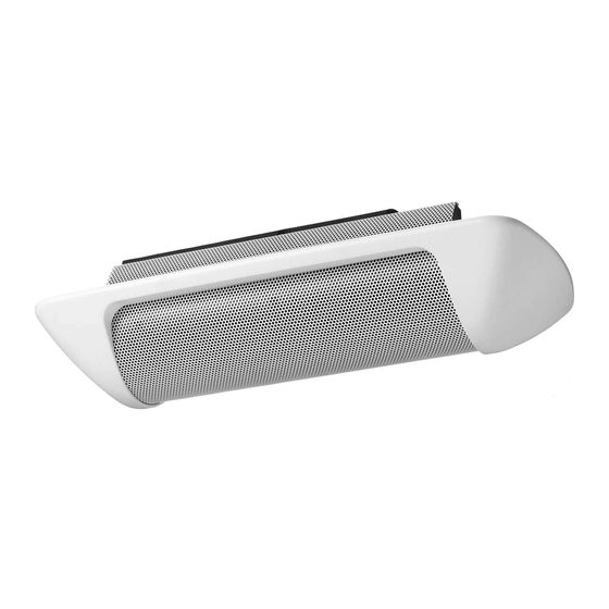
Toa H-1 Operating Instructions Manual
Speaker system
Hide thumbs
Also See for H-1:
- Operating instructions manual (12 pages) ,
- User manual (60 pages) ,
- Brochure & specs (6 pages)
Table of Contents
Advertisement
Quick Links
See also:
User Manual
SPEAKER SYSTEM
Please follow the instructions in this manual to obtain the optimum results from this unit.
We also recommend that you keep this manual handy for future reference.
TABLE OF CONTENTS
......................................................................................................................... 3
5.1. Direct Wall/Ceiling Mounting Without Using an Electrical Box ........................................ 5
5.2. Mounting the Speaker to an Electrical Box Using The Adapter Frame ........................... 8
5.3. Mounting the Speaker Directly to an Electrical Box ......................................................... 9
5.4. Removing the Trim Piece ................................................................................................ 9
Accessories .......................................................................................................................... 12
............................................................................................... 2
............................................................................................ 3
............................................................................................................ 4
.............................................................................................................. 11
.......................................................................................................... 12
OPERATING INSTRUCTIONS
..................................................... 10
.......................................................... 11
H-1
Advertisement
Table of Contents

Summary of Contents for Toa H-1
-
Page 1: Table Of Contents
OPERATING INSTRUCTIONS SPEAKER SYSTEM Please follow the instructions in this manual to obtain the optimum results from this unit. We also recommend that you keep this manual handy for future reference. TABLE OF CONTENTS 1. SAFETY PRECAUTIONS ....................2 2. GENERAL DESCRIPTION .................... -
Page 2: Safety Precautions
1. SAFETY PRECAUTIONS • Before installation or use, be sure to carefully read all the instructions in this section for correct and safe operation. • Be sure to follow all the precautionary instructions in this section, which contain important warnings and/or cautions regarding safety. -
Page 3: General Description
• The speaker's built-in crossover network circuitry features sharp cut-off characteristics that realize uniform energy radiation while suppressing unwanted input signals to the woofer or tweeter. • The H-1 Speaker System is designed with an emphasis on installation ease and safety, as well as easier conduit wiring when an electrical box is installed. -
Page 4: Nomenclature
Connector for impedance selection 255.6 (10 ") Detachable input connector 254 (10") • Accessory (Adapter Panel) 287.2 230.8 (For mounting the H-1 speaker) 255.6 (10 ") (For mounting to an electrical box) 254 (10") (For mounting to an electrical box) Unit : mm... -
Page 5: Installation
5. INSTALLATION 5.1. Direct Wall/Ceiling Mounting Without Using an Electrical Box Step 1. Adapter Panel mounting 1-1. Using the supplied hole pattern sheet as a guide, 287.2 (Adapter Panel) make an opening of the specified size in the wall or 268 (Mounting hole) ceiling panel. - Page 6 1-4. Clamp the wall or ceiling panel using the two board clamps, and secure with the clamp screws. Step 2. Wiring and impedance changes 2-1. Pull the cables out of the mounting hole in the wall or ceiling, then strip the insulation back about 5mm from the cable ends.
- Page 7 3-1. Align the four inward-facing holes in the speaker's mounting bracket with the corresponding holes in the Adapter Panel mounting tabs, then mount the speaker to the panel using the four supplied screws (M4 x 25 screws with both the spring washers and plain washers). H-1 speaker...
-
Page 8: Mounting The Speaker To An Electrical Box Using The Adapter Frame
5.2. Mounting the Speaker to an Electrical Box Using The Adapter Panel The H-1 speaker system can be mounted to walls or ceilings using an electrical box*. Mount the Adapter Panel to the electrical box as shown below. Further mounting procedures are the same as detailed in Steps 2 and 3. -
Page 9: Mounting The Speaker Directly To An Electrical Box
Electrical box Memo Electrical box mounting screws are attached to the H-1 speaker. H-1 speaker Note: The distance between the wall or ceiling surface and the box bottom surface must be 45 mm or more. When using the Raco 953 electrical box, be careful in installation because it is shallow. -
Page 10: Repainting The Grille And Trim Piece
6. REPAINTING THE GRILLE AND TRIM PIECE Follow the procedures below to change the color of the grille. 1. Remove the speaker's angle adjustment screw (1 piece). 2. Detach either of the two mounting brackets attached to the speaker. Mounting bracket Angle adjustment screw Grille mounting screw 3. -
Page 11: Protection Circuitry Information
8. EQUALIZATION • The H-1 is designed to provide good quality sound without additional equalization. However, by equalizing it as shown below, sounds can be made more powerful and intelligible. • Using a digital signal processor, make the following equalization setting. -
Page 12: Specifications
UNC No. 8-32 x 32 mm ....... 4 Spring washer ........4 Plain washer ........4 Traceability Information for Europe (EMC directive 2004/108/EC) Manufacturer: Authorized representative: TOA Corporation TOA Electronics Europe GmbH 7-2-1, Minatojima Nakamachi, Chuo-ku, Kobe, Hyogo, Suederstrasse 282, 20537 Hamburg, Japan Germany URL: http://www.toa.jp/ 533-06-075-1A...


Need help?
Do you have a question about the H-1 and is the answer not in the manual?
Questions and answers