HIKVISION Digital Video Recorder User Manual
Digital video recorder
Hide thumbs
Also See for Digital Video Recorder:
- User manual (198 pages) ,
- Quick operation manual (39 pages) ,
- Quick start manual (37 pages)
Table of Contents
Advertisement
Quick Links
Advertisement
Table of Contents

Related Manuals for HIKVISION Digital Video Recorder


Summary of Contents for HIKVISION Digital Video Recorder
-
Page 1: Digital Video Recorder
Digital Video Recorder User Manual UD.6L0202D1252A01... - Page 2 The content of this manual is furnished for informational use only, is subject to change without notice, and should not be construed as a commitment by Hangzhou Hikvision Digital Technology Co., Ltd. (Hikvision). Hikvision assumes no responsibility or liability for any errors or inaccuracies that may appear in the book.
- Page 3 User Manual of Digital Video Recorder Regulatory information FCC information This equipment has been tested and found to comply with the limits for a digital device, FCC compliance pursuant to part 15 of the FCC Rules. These limits are designed to provide reasonable protection against harmful interference when the equipment is operated in a commercial environment.
-
Page 4: Preventive And Cautionary Tips
User Manual of Digital Video Recorder Preventive and Cautionary Tips Before connecting and operating your DVR, please be advised of the following tips: • Ensure unit is installed in a well-ventilated, dust-free environment. • Unit is designed for indoor use only. - Page 5 User Manual of Digital Video Recorder Thank you for purchasing our product. If there is any question or request, please do not hesitate to contact dealer. This manual is applicable to the models listed in the following table. Series Model...
-
Page 6: Product Key Features
User Manual of Digital Video Recorder Product Key Features General Support HD-SDI camera connection; Each channel supports dual-stream. Main stream supports up to 1080P resolution and sub-stream supports up to 4CIF resolution; Independent configuration for each channel, including resolution, frame rate, bit rate, image quality, etc. - Page 7 User Manual of Digital Video Recorder and manual recording; Searching record files by events (alarm input/motion detection); Customization of tags, searching and playing back by tags; Locking and unlocking of record files; Local redundant recording; Searching and playing back record files by channel number, recording type, start time, end time, etc.;...
- Page 8 User Manual of Digital Video Recorder Remote parameters setup; remote import/export of device parameters; Remote viewing of the device status, system logs and alarm status; Remote keyboard operation; Remote locking and unlocking of control panel and mouse;...
-
Page 9: Table Of Contents
User Manual of Digital Video Recorder Table of Contents Product Key Features ..........................6 Chapter 1 Introduction ..........................12 Front Panels ........................... 13 IR Remote Control Operations ...................... 20 USB Mouse Operation ........................22 Input Method Description ......................23 Rear Panel ............................. 24 Chapter 2 Getting Started .......................... - Page 10 User Manual of Digital Video Recorder Chapter 6 Playback ............................73 Playing Back Record Files ......................74 6.1.1 Playing Back by Channel ..................... 74 6.1.2 Playing Back by Time ......................76 6.1.3 Playing Back by Event Search ..................... 78 6.1.4 Playing Back by Tag ......................
- Page 11 User Manual of Digital Video Recorder 9.4.2 Exporting Network Packet ....................138 9.4.3 Checking Network Status ....................140 9.4.4 Checking Network Statistics ....................140 Chapter 10 HDD Management ......................... 142 10.1 Initializing HDDs ........................143 10.2 Managing Network HDD ......................144 10.3 Managing eSATA ........................
-
Page 12: Chapter 1 Introduction
User Manual of Digital Video Recorder Chapter 1 Introduction... -
Page 13: Front Panels
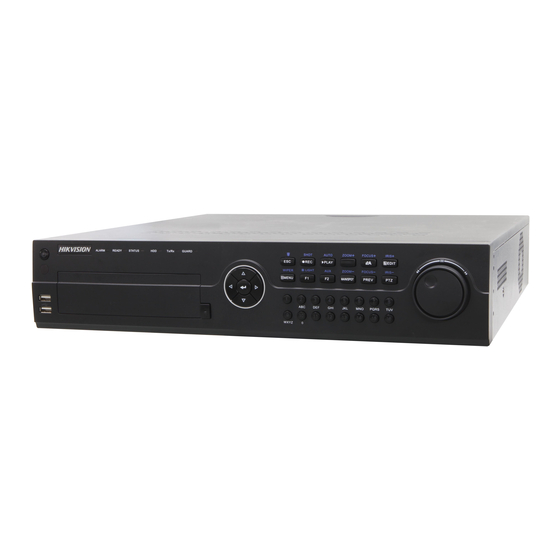
User Manual of Digital Video Recorder 1.1 Front Panels Figure 1. 1 Front Panel of DS-7204HFHI-SE & DS-7200HFHI-SL Figure 1. 2 Front Panel of DS-7208HFHI-SE Table 1. 1 Description of Front Panel Name Function Description Power indicator turns yellow when the power switch on the real POWER panel is turned on. - Page 14 User Manual of Digital Video Recorder Name Function Description Receiver for IR remote. IR Receiver Universal Serial Bus (USB) ports for additional devices such as USB Interface USB mouse and USB Hard Disk Drive (HDD). Switch between the numeric or letter input and functions of the SHIFT composite keys.
- Page 15 User Manual of Digital Video Recorder Name Function Description In Live View mode, these buttons can be used to cycle through channels. In PTZ control mode, it can control the movement of the PTZ camera. The ENTER button is used to confirm selection in any of the menu modes.
- Page 16 User Manual of Digital Video Recorder Name Function Description Enter numeral “1”; 1/MENU Access the main menu interface. Enter numeral “2”; Enter letters “ABC”; The F1 button when used in a list field will select all items in the list.
- Page 17 User Manual of Digital Video Recorder Name Function Description The ENTER button is used to confirm selection in any of the menu modes. It can also be used to tick checkbox fields. ENTER In Playback mode, it can be used to play or pause the video.
- Page 18 User Manual of Digital Video Recorder Name Function Description Switch to the corresponding channel in Live view or PTZ Control mode. Input numbers and characters in Edit mode. Alphanumeric Buttons Switch between different channels in Playback mode. The light of the button is blue when the corresponding channel is recording;...
- Page 19 User Manual of Digital Video Recorder Name Function Description It is also used to switch between input methods (upper and lowercase alphabet, symbols and numeric input). Edit text fields. When editing text fields, it will also function as a Backspace button to delete the character in front of the cursor.
-
Page 20: Ir Remote Control Operations
User Manual of Digital Video Recorder 1.2 IR Remote Control Operations The DVR may also be controlled with the included IR remote control, shown in Figure 1. 6. Batteries (2× AAA) must be installed before operation. Figure 1. 6 Remote Control The keys on the remote control closely resemble the ones found on the front panel. - Page 21 User Manual of Digital Video Recorder Name Description Alphanumeric Buttons Same as Alphanumeric buttons on front panel. EDIT Button Same as EDIT/IRIS+ button on front panel. A Button Same as A/FOCUS+ button on front panel. Same as REC/SHOT button on front panel.
-
Page 22: Usb Mouse Operation
User Manual of Digital Video Recorder 1.3 USB Mouse Operation A regular 3-button (Left/Right/Scroll-wheel) USB mouse can also be used with this DVR. To use a USB mouse: 1. Plug USB mouse into one of the USB interfaces on the front panel of the DVR. -
Page 23: Input Method Description
User Manual of Digital Video Recorder 1.4 Input Method Description Figure 1. 7 Soft Keyboard Description of the buttons on the soft keyboard: Table 1. 7 Description of the Soft Keyboard Icons Icons Description Icons Description English Capital English Numbers... -
Page 24: Rear Panel
User Manual of Digital Video Recorder 1.5 Rear Panel Figure 1. 8 DS-7204HFHI-SL Figure 1. 9 DS-7208HFHI-SL Figure 1. 10 DS-7204HFHI-SE Figure 1. 11 DS-7204HFHI-ST Figure 1. 12 DS-7208HFHI-SE and DS-7208HFHI-ST Item Description VIDEO IN HD-SDI interface for video input. - Page 25 User Manual of Digital Video Recorder Item Description HDMI HDMI video output connector. USB Port Universal Serial Bus (USB) port for additional devices. Network Interface Connector for network RS-485 Interface Connector for RS-485 devices. Power Supply DC 12V power supply.
- Page 26 User Manual of Digital Video Recorder Item Description Ground LINE IN BNC connector for audio input. eSATA Connects external SATA HDD, CD/DVD-RW. RS-232 Interface Connector for RS-232 devices. RS-485 termination switch. Termination Switch Up position is not terminated. Down position is terminated with 120Ω resistance.
-
Page 27: Chapter 2 Getting Started
User Manual of Digital Video Recorder Chapter 2 Getting Started... -
Page 28: Starting Up And Shutting Down The Dvr
User Manual of Digital Video Recorder 2.1 Starting Up and Shutting Down the DVR Purpose: Proper startup and shutdown procedures are crucial to expanding the life of the DVR. Before you start: Check that the voltage of the extra power supply is the same with the DVR’s requirement, and the ground connection is working properly. - Page 29 User Manual of Digital Video Recorder 1. Press and hold the POWER button on the front panel for 3 seconds. 2. Enter the administrator’s username and password in the dialog box for authentication. 3. Click the Yes button. Do not press the POWER button again when the system is shutting down.
-
Page 30: Using The Wizard For Basic Configuration
User Manual of Digital Video Recorder 2.2 Using the Wizard for Basic Configuration By default, the Setup Wizard will start once the DVR has loaded, as shown in Figure 2. 3. Steps: 1. Please select the system language in the drop-down list on your demand. - Page 31 User Manual of Digital Video Recorder Figure 2. 5 Login Window 4. Enter the admin password. By default, the password is 12345. 5. To change the admin password, check the New Admin Password checkbox. Enter the new password and confirm the password in the given fields.
- Page 32 User Manual of Digital Video Recorder DS-8100HFHI-ST Other Models Figure 2. 7 Network Configuration 8. Click Next button after you having configured the network parameters, which will take you to the HDD Management window, shown in Figure 2. 8. Figure 2. 8 HDD Management 9.
- Page 33 User Manual of Digital Video Recorder Figure 2. 9 Record Settings 11. Click Copy to copy the recording setting to other cameras. 12. Click OK to save the settings and exit the wizard.
-
Page 34: Chapter 3 Live View
User Manual of Digital Video Recorder Chapter 3 Live View... -
Page 35: Introduction Of Live View
User Manual of Digital Video Recorder 3.1 Introduction of Live View Live view shows you the video image getting from each camera in real time. The DVR will automatically enter Live View mode when powered on. It is also at the very top of the menu hierarchy, thus hitting the ESC many times (depending on which menu you’re on) will bring you to the Live View mode. -
Page 36: Operations In Live View Mode
User Manual of Digital Video Recorder 3.2 Operations in Live View Mode In live view mode, there are many functions provided. The functions are listed below. • Single Screen: show only one screen on the monitor. • Multi-screen: show multiple screens on the monitor simultaneously. -
Page 37: Using The Mouse In Live View
User Manual of Digital Video Recorder 3.2.2 Using the Mouse in Live View Table 3. 4 Mouse Operation in Live View Name Description Menu Enter the main menu of the system by right clicking the mouse. Single Screen Switch to the single full screen by choosing channel number from the dropdown list. -
Page 38: Using An Auxiliary Monitor
User Manual of Digital Video Recorder DS-7200HFHI-SL&SE&ST DS-7300HFHI-ST & DS-8100HFHI-ST Figure 3. 1 Right-click Menu 3.2.3 Using an Auxiliary Monitor Certain features of the Live View are also available while in an Aux monitor. These features include: • Single Screen: Switch to a full screen display of the selected camera. Camera can be selected from a dropdown list. -
Page 39: Quick Setting Toolbar In Live View Mode
User Manual of Digital Video Recorder Figure 3. 2 Switch Main and Aux Output 2. Use the mouse wheel to double-click on the screen again to switch to the Aux output, or click Cancel to cancel the operation. 3. Select the Menu Output Mode to Main CVBS from the right-click menu on the CVBS output monitor. - Page 40 User Manual of Digital Video Recorder record during the last five minutes. Digital Zoom can zoom in the selected area to the full screen. Click and draw to select the area to zoom in, as shown in Figure 3. 5.
-
Page 41: Channel-Zero Encoding
User Manual of Digital Video Recorder 3.3 Channel-zero Encoding This chapter is only applicable to DS-7300HFHI-ST and DS-8100HFHI-ST. Purpose: Sometimes you need to get a remote view of many channels in real time from web browser or CMS(Client Management System) software, in order to decrease the bandwidth requirement without affecting the image quality, channel-zero encoding is supported as an option for you. -
Page 42: Adjusting Live View Settings
User Manual of Digital Video Recorder 3.4 Adjusting Live View Settings Purpose: Live View settings can be customized according to different needs. You can configure the output interface, dwell time for screen to be shown, mute or turning on the audio, the screen number for each channel, etc. -
Page 43: User Logout
User Manual of Digital Video Recorder 3.5 User Logout Purpose: After logging out, the monitor turns to the live view mode and if you want to do some operation, you need to enter user name and password to log in again. -
Page 44: Chapter 4 Ptz Controls
User Manual of Digital Video Recorder Chapter 4 PTZ Controls... -
Page 45: Configuring Ptz Settings
User Manual of Digital Video Recorder 4.1 Configuring PTZ Settings Purpose: Follow the procedure to set the parameters for PTZ. The configuring of the PTZ parameters should be done before you set the PTZ camera. Before you start: Check that the PTZ and the DVR are connected properly through RS-485 interface. -
Page 46: Setting Ptz Presets, Patrols & Patterns
User Manual of Digital Video Recorder 4.2 Setting PTZ Presets, Patrols & Patterns Before you start: Please make sure that the presets, patrols and patterns should be supported by PTZ protocols. 4.2.1 Customizing Presets Purpose: Follow the steps to set the Preset location which you want the PTZ camera to point to when an event takes place. -
Page 47: Calling Presets
User Manual of Digital Video Recorder 4.2.2 Calling Presets Purpose: This feature enables the camera to point to a specified position such as a window when an event takes place. Call preset in the PTZ setting interface: Steps: 1. Enter the PTZ Control interface. -
Page 48: Customizing Patrols
User Manual of Digital Video Recorder 3. Double-click the preset you want to call in the Preset list. 4.2.3 Customizing Patrols Purpose: Patrols can be set to move the PTZ to a set of different key points sequentially and have it stay there for a set duration before moving on to the next key point. -
Page 49: Calling Patrols
User Manual of Digital Video Recorder Repeat the above steps to add more key points. You can also click to delete the corresponding key point and click to delete all the key points. Figure 4. 8 KeyPoints Deletion 4.2.4 Calling Patrols Purpose: Calling a patrol makes the PTZ to move according the predefined patrol path. -
Page 50: Customizing Patterns
User Manual of Digital Video Recorder toolbar, to show the PTZ control panel. 2. Choose Patrol on the control bar. 3. Double-click the patrol you want to call, or click to select the patrol and click to call the patrol. -
Page 51: Calling Patterns
User Manual of Digital Video Recorder 4. Click to save the pattern. Repeat the above steps to save more patterns. 4.2.6 Calling Patterns Purpose: Follow the procedure to move the PTZ camera according to the predefined patterns. Calling pattern in the PTZ setting interface Steps: 1. -
Page 52: Ptz Control Panel
User Manual of Digital Video Recorder 4.3 PTZ Control Panel In the Live View mode, you can press the PTZ Control button on the front panel or on the remote control, or choose the PTZ Control icon to enter the PTZ panel. -
Page 53: Chapter 5 Record Settings
User Manual of Digital Video Recorder Chapter 5 Record Settings... -
Page 54: Configuring Encoding Parameters
User Manual of Digital Video Recorder 5.1 Configuring Encoding Parameters Before you start: 1. Make sure that the HDD has already been installed. If not, please install a HDD and initialize it. (Menu>HDD>General) Figure 5. 1 HDD- General 2. Click Advance to check the storage mode of the HDD. - Page 55 User Manual of Digital Video Recorder 1) Select the Record tab to configure. 2) Select a camera number in the camera dropdown list. You can configure the stream type, the resolution, the video quality and other parameters on demand for Main Stream(Normal) and Main Stream(Event) respectively.
- Page 56 User Manual of Digital Video Recorder see Chapter 10.4.2 Setting HDD Property. 3. Set encoding parameters for sub-stream. 1) Select the Substream tab. Figure 5. 5 Sub-stream Encoding 2) Select a camera in the camera dropdown list. 3) Configure the parameters.
-
Page 57: Configuring Record Schedule
User Manual of Digital Video Recorder 5.2 Configuring Record Schedule Purpose: Set the record schedule, and then the camera will automatically start/stop recording according to the configured schedule. Steps: 1. Enter the Record Schedule interface. Menu> Record> Schedule DS-7200HFHI-SL&SE&ST DS-7300HFHI-ST and DS-8100HFHI-ST Figure 5. - Page 58 User Manual of Digital Video Recorder Figure 5. 7 Edit Schedule- All Day To arrange other schedule, leave the All Day checkbox blank and set the Start/End time. Figure 5. 8 Edit Schedule- Set Time Period Up to 8 periods can be configured for each day. And the time periods cannot be overlapped each other.
- Page 59 User Manual of Digital Video Recorder The Holiday option is available when you enable holiday schedule in Holiday settings. See Chapter 5.6 Configuring Holiday Record. Click OK to save setting and back to upper level menu. Draw the schedule Click on the color icon to select a record type in the event list on the right-side of the interface.
- Page 60 User Manual of Digital Video Recorder Figure 5. 12 Copy Schedule to Other Channels 5. Click Apply in the Record Schedule interface to save the settings.
-
Page 61: Configuring Motion Detection Record
User Manual of Digital Video Recorder 5.3 Configuring Motion Detection Record Purpose: Follow the steps to set the motion detection parameters. In the live view mode, once a motion detection event takes place, the DVR can analyze it and do many actions to handle it. Enabling motion detection function can trigger certain channels to start recording, or trigger full screen monitoring, audio warning, notifying the surveillance center, sending email and so on. - Page 62 User Manual of Digital Video Recorder Figure 5. 15 Motion Detection Handling 5) Select the channels which you want the motion detection event to trigger recording. 6) Click Apply to save the settings. 7) Click OK to back to the upper level menu.
-
Page 63: Configuring Alarm Triggered Record
User Manual of Digital Video Recorder 5.4 Configuring Alarm Triggered Record The DS-7200HFHI-SL&SE&ST series DVR does not support the alarm input by default. Purpose: Follow the procedure to configure alarm triggered recording. Steps: 1. Enter the Alarm setting interface. Menu> Configuration> Alarm Figure 5. - Page 64 User Manual of Digital Video Recorder Figure 5. 18 Alarm Handling Choose the alarm triggered recording channel. Check the checkbox to select channel. Click Apply to save settings. Click OK to back to the upper level menu. Repeat the above steps to configure other alarm input parameters.
-
Page 65: Manual Record
User Manual of Digital Video Recorder 5.5 Manual Record Purpose: Follow the steps to set parameters for the manual record. Using manual record, you don’t need to set a schedule for recording. Steps: 1. Enter the Manual settings interface. Menu> Manual Figure 5. -
Page 66: Configuring Holiday Record
User Manual of Digital Video Recorder 5.6 Configuring Holiday Record Purpose: Follow the steps to configure the record schedule on holiday for that year. You may want to have different plan for recording on holiday. Steps: 1. Enter the Record setting interface. - Page 67 User Manual of Digital Video Recorder 5) Click Apply to save settings. 6) Click OK to exit the Edit interface. 4. Configure the record schedule. Please refer to the Chapter 5.2 Configuring Record Schedule, while you may choose Holiday in the Schedule dropdown list, or you can draw the schedule on the timeline of Holiday.
-
Page 68: Configuring Redundant Recording
User Manual of Digital Video Recorder 5.7 Configuring Redundant Recording Purpose: Enabling redundant recording, which means saving the record files not only in the R/W HDD but also in the redundant HDD, will effectively enhance the data safety and reliability. - Page 69 User Manual of Digital Video Recorder Figure 5. 27 Encoding Record 2) Select Camera you want to configure. 3) Check the checkbox of Redundant Record. 4) Click Apply to save settings. If the encoding parameters can also be used to other channels, click Copy and choose the channel you want to...
-
Page 70: Configuring Hdd Group For Recording
User Manual of Digital Video Recorder 5.8 Configuring HDD Group for Recording Purpose: You can group the HDDs and save the record files in certain HDD group. Steps: 1. Enter HDD setting interface. Menu>HDD>Advanced Figure 5. 28 HDD General 2. Select Advanced on the left bar. -
Page 71: Files Protection
User Manual of Digital Video Recorder 5.9 Files Protection Purpose: You can lock the recorded files or set the HDD property to Read-only to protect the record files from being overwritten. Protect file by locking the record files Steps: 1. Enter Playback setting interface. - Page 72 User Manual of Digital Video Recorder Figure 5. 32 Unlocking Attention Protect file by setting HDD property to Read-only Before you start: To edit HDD property, you need to set the storage mode of the HDD to Group. See Chapter 10.4 Managing HDD Group.
-
Page 73: Chapter 6 Playback
User Manual of Digital Video Recorder Chapter 6 Playback... -
Page 74: Playing Back Record Files
User Manual of Digital Video Recorder 6.1 Playing Back Record Files 6.1.1 Playing Back by Channel Purpose: Play back the recorded video files of a specific channel in the live view mode. Channel switch is supported. OPTION 1 Choose a channel in live view mode using the mouse and click the button in the quick setting toolbar. - Page 75 User Manual of Digital Video Recorder DS-7200HFHI-SL&SE&ST DS-7300HFHI-ST & DS-8100HFHI-ST Figure 6. 2 Right-click Menu under Live View Front Panel: press PLAY button to play back record files of the channel under single-screen live view mode. Under multi-screen live view mode, the recorded files of the top-left channel will be played back.
-
Page 76: Playing Back By Time
User Manual of Digital Video Recorder Figure 6. 4 Toolbar of Playback Table 6. 1 Detailed Explanation of Playback Toolbar Button Operation Button Operation Button Operation Button Operation Audio on/ Start/Stop 30s forward 30s reverse Mute clipping Add default Speed down... - Page 77 User Manual of Digital Video Recorder If there are record files for that camera in that day, in the calendar, the icon for that day is displayed as . Otherwise it is displayed as In the Playback interface: The toolbar in the bottom part of Playback interface can be used to control playing process, as shown in Figure 6.
-
Page 78: Playing Back By Event Search
User Manual of Digital Video Recorder Playback progress bar: use the mouse to click any point of the progress bar or drag the progress bar to locate special frames. 6.1.3 Playing Back by Event Search Purpose: Play back recording files on one or several channels searched out by restricting event type (e.g. alarm input and motion detection). - Page 79 User Manual of Digital Video Recorder Figure 6. 9 Motion Search Interface 4. Click Search button to get the search result information. You may refer to the right-side bar for the result. Figure 6. 10 Search Result Bar (Alarm In and Motion) 5.
- Page 80 User Manual of Digital Video Recorder 7. Playback management. The toolbar in the bottom part of Playback interface can be used to control playing process. Figure 6. 11 Interface of Playback by Event Figure 6. 12 Toolbar of Playback by Event Table 6.
-
Page 81: Playing Back By Tag
User Manual of Digital Video Recorder 6.1.4 Playing Back by Tag Purpose: Video tag allows you to record related information like people and location of a certain time point during playback. You are also allowed to use video tag(s) to search for record files and position time point. - Page 82 User Manual of Digital Video Recorder Steps: 1. Select the Tag from the drop-down list in the Playback interface. 2. Choose channels, edit start time and end time, and then click Search to enter Search Result interface. You can enter keyword in the textbox to search the tag on your command.
-
Page 83: Playing Back By System Logs
User Manual of Digital Video Recorder Figure 6. 17 Toolbar of Playback by Tag Table 6. 4 Detailed Explanation of Playback-by-tag Toolbar Button Operation Button Operation Button Operation Button Operation Audio on/ Start/Stop 30s forward 30s reverse Mute clipping Add default... - Page 84 User Manual of Digital Video Recorder Figure 6. 18 System Log Search Interface 3. Choose a log with record file and click button to enter Playback interface. If there is no record file at the time point of the log, the message box “No result found” will pop up.
-
Page 85: Playing Back External File
User Manual of Digital Video Recorder 6.1.6 Playing Back External File Purpose: Perform the following steps to look up and play back files in the external devices. Steps: 1. Enter Tag Search interface. Menu>Playback 2. Select the External File in the drop-down list on the top-left side. -
Page 86: Auxiliary Functions Of Playback
User Manual of Digital Video Recorder 6.2 Auxiliary Functions of Playback 6.2.1 Playing Back Frame by Frame Purpose: Play video files frame by frame, in order to check image details of the video when abnormal events happen. Steps: • Using a Mouse Go to Playback interface and click button until the speed changes to Single frame. - Page 87 User Manual of Digital Video Recorder 3. Click and drag the mouse to draw area(s). You can click button to set the full screen as target searching area. After drawing area(s), press button to execute smart search in this area.
-
Page 88: Digital Zoom
User Manual of Digital Video Recorder Button Operation Button Operation Button Operation Button Operation Pause reverse Pause play/ play/ Play/ Reverse play/ Stop Speed up Single-frame Single-frame play reverse play customized Speed down default tag management Scaling Process bar Video type... - Page 89 User Manual of Digital Video Recorder You can play back record files of multi-channel reversely. Up to 16-ch (with 1920*1080 resolution) simultaneous reverse playback is supported. Steps: 1. Enter Playback interface. Menu>Playback 2. Check more than one checkboxes to select multiple channels and click to select a date on the calendar.
-
Page 90: Chapter 7 Backup
User Manual of Digital Video Recorder Chapter 7 Backup... -
Page 91: Backing Up Record Files
User Manual of Digital Video Recorder 7.1 Backing up Record Files Before you start: Please insert the backup device(s) into the device. 7.1.1 Quick Export Purpose: Export record files to backup device(s) quickly. Steps: 1. Enter Video Export interface. Menu>Export>Normal 2. -
Page 92: Backing Up By Normal Video Search
User Manual of Digital Video Recorder Stay in the Exporting interface until all record files are being exported. Figure 7. 3 Export Finished 4. Check backup result. Choose the record file in Export interface and click button to check it. - Page 93 User Manual of Digital Video Recorder Figure 7. 5 Result of Normal Video Search for Backup 3. Select record files you want to back up. Click button to play the record file if you want to check it. Check the checkbox before the record files you want to back up.
- Page 94 User Manual of Digital Video Recorder Figure 7. 7 Export by Normal Video Search using USB Writer Stay in the Exporting interface until all record files are exported with pop-up message box “Export finished”. Figure 7. 8 Export Finished 5. Check backup result.
- Page 95 User Manual of Digital Video Recorder Figure 7. 10 Checkup of Export Result using USB Writer Backup using eSATA HDDs Steps: 1. Enter Record>Advanced and set the usage of eSATA HDD at “Export”. Menu>Record>Advanced Choose eSATA and set its usage at Export. Click Yes when pop-up message box “System will reboot automatically if the usage of eSATA is changed.
- Page 96 User Manual of Digital Video Recorder Figure 7. 11 Result of Normal Video Search for Backup 4. Export. Click Export button and start backup. Please format the eSATA first when using it for the first time. If the inserted eSATA HDD is not recognized: •...
-
Page 97: Backing Up By Event Search
User Manual of Digital Video Recorder Figure 7. 13 Export Finished 5. Check backup result. Choose the record file in Export interface and click button to check it. The Player player.exe will be exported automatically during record file export. Figure 7. 14 Checkup of Export Result Using eSATA HDD 7.1.3 Backing up by Event Search... - Page 98 User Manual of Digital Video Recorder 3) Click Search button to enter the Search Result interface. Figure 7. 15 Event Search for Backup- Motion Figure 7. 16 Event Search for Backup- Alarm Input 3. Select record files to export. 1) Select an alarm input in the list and click Quick Export button to enter Export interface.
- Page 99 User Manual of Digital Video Recorder Figure 7. 18 Result of Video Search by Alarm Input 4) Click Details button to view detailed information of the record file, e.g. start time, end time, file size, etc. The size of the currently selected files is displayed in the lower-right corner of the window.
- Page 100 User Manual of Digital Video Recorder 4. Export. Click the Export button and start backing up. If the inserted USB device is not recognized: • Click the Refresh button. • Reconnect device. • Check for compatibility from vendor. You can also format USB flash drive or USB HDDs via the device.
-
Page 101: Backing Up Video Clips
User Manual of Digital Video Recorder Figure 7. 23 Checkup of Event Export Result Using USB Flash Drive 7.1.4 Backing up Video Clips Purpose: You may also select video clips to export directly during Playback, using USB devices, such as USB flash drives, USB HDDs, and USB writers. - Page 102 User Manual of Digital Video Recorder 4. Click Yes to save video clips and enter Export interface, or click No to quit without saving video clips. Figure 7. 25 Attention to Video Clip Saving 5. Export. Click Export button and start backup.
- Page 103 User Manual of Digital Video Recorder The Player player.exe will be exported automatically during record file export. Figure 7. 28 Checkup of Video Clips Export Result Using USB Flash Drive...
-
Page 104: Managing Backup Devices
User Manual of Digital Video Recorder 7.2 Managing Backup Devices Management of USB flash drives and USB HDDs. Steps: 1. Enter Search Result interface of record files. Menu>Export>Normal Set search condition and click Search button to enter Search Result interface. - Page 105 User Manual of Digital Video Recorder Figure 7. 31 USB Flash Drive Management Click New Folder button if you want to create a new folder in the backup device. Select a record file or folder in the backup device and press button if you want to delete it.
- Page 106 User Manual of Digital Video Recorder At least one record file shall be selected. Figure 7. 33 Result of Normal Video Search for Backup 3. Backup device management. Figure 7. 34 USB Writer Management Click Erase button if you want to erase the files from a re-writable CD/DVD.
-
Page 107: Chapter 8 Alarm Settings
User Manual of Digital Video Recorder Chapter 8 Alarm Settings... -
Page 108: Setting Motion Detection
User Manual of Digital Video Recorder 8.1 Setting Motion Detection Steps: 1. Enter Motion Detection interface of Camera Management and choose a camera you want to set up motion detection. Menu> Camera> Motion Figure 8. 1 Motion Detection Setup Interface 2. - Page 109 User Manual of Digital Video Recorder Figure 8. 3 Set Trigger Camera of Motion Detection 4. Set arming schedule of the channel. Select Arming Schedule tab to set the channel’s arming schedule. Choose one day of a week and up to eight time periods can be set within each day. Or you can click the Copy button to copy the time period settings to other day(s).
- Page 110 User Manual of Digital Video Recorder Figure 8. 5 Copy Settings of Motion Detection...
-
Page 111: Setting Sensor Alarms
User Manual of Digital Video Recorder 8.2 Setting Sensor Alarms Purpose: Set up handling method of an external sensor alarm. Steps: 1. Enter Alarm Settings of System Configuration and select an alarm input. Menu> Configuration> Alarm Select Alarm Input tab to enter Alarm Input Settings interface. - Page 112 User Manual of Digital Video Recorder Figure 8. 8 Set Arming Schedule of Alarm Input 6. If necessary, select PTZ Linking tab and set PTZ linkage of the alarm input. Set PTZ linking parameters and click the OK button to complete the settings of the alarm input.
- Page 113 User Manual of Digital Video Recorder Figure 8. 10 Copy Settings of Alarm Input...
-
Page 114: Detecting Video Loss
User Manual of Digital Video Recorder 8.3 Detecting Video Loss Purpose: Detect video loss of a channel and take alarm response action(s). Steps: 1. Enter Video Loss interface of Camera Management and select a channel you want to detect. Menu> Camera> Video Loss Figure 8. - Page 115 User Manual of Digital Video Recorder 4. Select Handling tab to set up alarm response action of video loss (please refer to Chapter 8.6 Setting Alarm Response Actions). 5. Click the OK button to complete the video loss settings of the channel.
-
Page 116: Detecting Video Tampering
User Manual of Digital Video Recorder 8.4 Detecting Video Tampering Purpose: Trigger alarm when the lens is covered and take alarm response action(s). Steps: 1. Enter Video Tampering interface of Camera Management and select a channel you want to detect video tampering. - Page 117 User Manual of Digital Video Recorder 8.6 Setting Alarm Response Actions). Repeat the above steps to set arming schedule of other days of a week. You can also use Copy button to copy an arming schedule to other days. 4) Click the OK button to complete the video tampering settings of the channel.
-
Page 118: Handling Exceptions
User Manual of Digital Video Recorder 8.5 Handling Exceptions Purpose: Exception settings refer to the handling method of various exceptions, e.g. • HDD Full: The HDD is full. • HDD Error: Writing HDD error, unformatted HDD, etc. • Network Disconnected: Disconnected network cable. -
Page 119: Setting Alarm Response Actions
User Manual of Digital Video Recorder 8.6 Setting Alarm Response Actions Purpose: Take alarm response actions will be activated when an alarm or exception occurs, including Full Screen Monitoring, Audible Warning (buzzer), Notify Surveillance Center, Send Email and Trigger Alarm Output. - Page 120 User Manual of Digital Video Recorder Choose one day of a week and up to 8 time periods can be set within each day. Time periods shall not be repeated or overlapped. Figure 8. 17 Set Arming Schedule of Alarm Output 3.
-
Page 121: Triggering Or Clearing Alarm Output Manually
User Manual of Digital Video Recorder 8.7 Triggering or Clearing Alarm Output Manually Purpose: Sensor alarm can be triggered or cleared manually. If “Manually Clear” is selected in the dropdown list of dwell time of an alarm output, the alarm can be cleared only by clicking Clear button in the following interface. -
Page 122: Chapter 9 Network Settings
User Manual of Digital Video Recorder Chapter 9 Network Settings... -
Page 123: Configuring General Settings
User Manual of Digital Video Recorder 9.1 Configuring General Settings Purpose: Network settings must be properly configured before you operate DVR over network. Steps: 1. Enter the Network Settings interface. Menu > Configuration > Network DS-8100HFHI-ST Other Models Figure 9. 1 Network Settings Interface 2. - Page 124 User Manual of Digital Video Recorder 4. After having configured the general settings, click the Apply button to save the settings. Working Mode There are two 10M/100M/1000M NIC cards provided by the DS-8100HFHI-ST series device, and it allows the device to work in the Multi-address, Load Balance and Net-fault Tolerance modes.
-
Page 125: Configuring Advanced Settings
User Manual of Digital Video Recorder 9.2 Configuring Advanced Settings 9.2.1 Configuring PPPoE Settings Purpose: The DVR also allows access by Point-to-Point Protocol over Ethernet (PPPoE). Steps: 1. Enter the Network Settings interface. Menu > Configuration > Network 2. Select the PPPoE tab to enter the PPPoE Settings interface. - Page 126 User Manual of Digital Video Recorder Figure 9. 3 DDNS Settings Interface 3. Check the DDNS checkbox to enable this feature. 4. Select DDNS Type. Five different DDNS types are selectable: IPServer, DynDNS, PeanutHull, NO-IP and HiDDNS. IPServer: Enter Server Address for IPServer.
- Page 127 User Manual of Digital Video Recorder Figure 9. 7 NO-IP Settings Interface HiDDNS: 1) The Server Address of the HiDDNS server appears by default: www.hik-online.com. 2) Enter the Device Domain Name. You can use the alias you registered in the HiDDNS server or define a new device domain name.
- Page 128 User Manual of Digital Video Recorder Figure 9. 10 Register the Device The device name can only contain the lower-case English letter, numeric and ‘-’; and it must start with the lower-case English letter and cannot end with ‘-’. Access the Device via Web Browser or Client Software After having successfully registered the device on the HiDDNS server, you can access your device via web browser or Client Software with the Device Domain Name (Device Name).
-
Page 129: Configuring Ntp Server
User Manual of Digital Video Recorder Figure 9. 11 Access Device via iVMS4200 5. Click the Apply button to save and exit the interface. 9.2.3 Configuring NTP Server Purpose: A Network Time Protocol (NTP) Server can be configured on your DVR to ensure the accuracy of system date/time. -
Page 130: Configuring Snmp
User Manual of Digital Video Recorder 9.2.4 Configuring SNMP Purpose: You can use SNMP protocol to get device status and parameters related information. Steps: 1. Enter the Network Settings interface. Menu > Configuration > Network 2. Select the SNMP tab to enter the SNMP Settings interface. - Page 131 User Manual of Digital Video Recorder Before you start: If you want to enable the UPnP™ function of the device, you must enable the UPnP™ function of the router to which your device is connected. When the network working mode of the device is set as multi-address, the Default Route of the device should be in the same network segment as that of the LAN IP address of the router.
-
Page 132: Configuring The Remote Alarm Host
User Manual of Digital Video Recorder the other ports should be between 1 and 65535 and the value must be different from each other. If multiple devices are configured for the UPnP™ settings under the same router, the value of the port No. -
Page 133: Configuring Multicast
User Manual of Digital Video Recorder System) software (e.g., iVMS-4200) is installed, and the Alarm Host Port must be the same as the alarm monitoring port configured in the software (default port is 7200). Figure 9. 20 Configure Alarm Host 4. -
Page 134: Configuring Server And Http Ports
User Manual of Digital Video Recorder Figure 9. 22 RTSP Settings Interface 3. Enter the RTSP port in the text field of RTSP Service Port. The default RTSP port is 554, and you can change it according to different requirements. - Page 135 User Manual of Digital Video Recorder Before configuring the Email settings, the DVR must be connected to a local area network (LAN) that maintains an SMTP mail server. The network must also be connected to either an intranet or the Internet depending on the location of the e-mail accounts to which you want to send notification.
- Page 136 User Manual of Digital Video Recorder 5. You can click the Test button to test whether your Email settings work. The corresponding Attention message box pops up. Figure 9. 25 Email Testing Attention...
-
Page 137: Checking Network Traffic
User Manual of Digital Video Recorder 9.3 Checking Network Traffic Purpose: You can check the network traffic to obtain real-time information of DVR such as linking status, MTU, sending/receiving rate, etc. Steps: 1. Enter the Network Traffic interface. Menu > Maintenance > Net Detect Figure 9. -
Page 138: Configuring Network Detection
User Manual of Digital Video Recorder 9.4 Configuring Network Detection Purpose: You can obtain network connecting status of DVR through the network detection function, including network delay, packet loss, etc. 9.4.1 Testing Network Delay and Packet Loss Steps: 1. Enter the Network Traffic interface. - Page 139 User Manual of Digital Video Recorder 3. Select the backup device from the dropdown list of Device Name. Click the Refresh button if the connected local backup device cannot be displayed. When it fails to detect the backup device, please check whether it is compatible with the DVR. You can format the backup device if the format is incorrect.
-
Page 140: Checking Network Status
User Manual of Digital Video Recorder 9.4.3 Checking Network Status Purpose: You can also check the network status and quick set the network parameters in this interface. Steps: Click Status on the right bottom of the page. Figure 9. 31 Checking Network Status If the network is normal the following message box pops out. - Page 141 User Manual of Digital Video Recorder 1. Enter the Network Statistics interface. Menu > Maintenance> Net Detect 2. Click the Network Stat. tab to enter the Network Statistics menu. Figure 9. 34 Network Stat. Interface 3. View the bandwidth of Remote Live View, bandwidth of Remote Playback, and bandwidth of Net Total Idle.
-
Page 142: Chapter 10 Hdd Management
User Manual of Digital Video Recorder Chapter 10 HDD Management... -
Page 143: Initializing Hdds
User Manual of Digital Video Recorder 10.1 Initializing HDDs Purpose: A newly installed hard disk drive (HDD) must be initialized before it can be used with your DVR. Steps: 1. Enter the HDD Information interface. Menu > HDD>General. Figure 10. 1 HDD Information Interface 2. -
Page 144: Managing Network Hdd
User Manual of Digital Video Recorder 10.2 Managing Network HDD Purpose: You can add the allocated NAS or disk of IP SAN to DVR, and use it as network HDD. Steps: Enter the HDD Information interface. Menu > HDD>General Figure 10. 5 HDD Information Interface 2. - Page 145 User Manual of Digital Video Recorder Figure 10. 7 Add NAS Disk • Add IP SAN: 1) Enter the NetHDD IP address in the text field. 2) Click the Search button to the available IP SAN disks. 3) Select the IP SAN disk from the list shown below.
-
Page 146: Managing Esata
User Manual of Digital Video Recorder 10.3 Managing eSATA Purpose: When there is an external eSATA device connected to DVR, you can configure eSATA for the use of Record or Export, and you can manage the eSATA in the DVR. -
Page 147: Managing Hdd Group
User Manual of Digital Video Recorder 10.4 Managing HDD Group 10.4.1 Setting HDD Groups Purpose: Multiple HDDs can be managed in groups. Video from specified channels can be recorded onto a particular HDD group through HDD settings. Steps: 1. Enter the Storage Mode interface. -
Page 148: Setting Hdd Property
User Manual of Digital Video Recorder Figure 10. 14 Local HDD Settings Interface 7. Select the Group number for the current HDD. The default group No. for each HDD is 1. 8. Click the OK button to confirm the settings. - Page 149 User Manual of Digital Video Recorder Figure 10. 16 Set HDD Property 3. Set the HDD property to R/W, Read-only or Redundancy. 4. Click the OK button to save the settings and exit the interface. 5. In the HDD Information menu, the HDD property will be displayed in the list.
-
Page 150: Configuring Quota Mode
User Manual of Digital Video Recorder 10.5 Configuring Quota Mode Purpose Each camera can be configured with allocated quota for the storage of recorded files. Steps 1. Enter the Storage Mode interface. Menu > HDD > Advanced 2. Set the Mode to Quota, as shown in Figure 10. 17. - Page 151 User Manual of Digital Video Recorder Figure 10. 19 Copy Settings to Other Camera(s) 6. Select the camera (s) to be configured with the same quota settings. You can also click the checkbox of Analog to select all cameras. 7. Click the OK button to finish the Copy settings and back to the Storage Mode interface.
-
Page 152: Checking Hdd Status
User Manual of Digital Video Recorder 10.6 Checking HDD Status Purpose: You may check the status of the installed HDDs on DVR so as to take immediate check and maintenance in case of HDD failure. Checking HDD Status in HDD Information Interface Steps: 1. -
Page 153: Checking S.m.a.r.t Information
User Manual of Digital Video Recorder 10.7 Checking S.M.A.R.T Information Purpose: The S.M.A.R.T. (Self-Monitoring, Analysis and Reporting Technology) is a monitoring system for HDD to detect and report on various indicators of reliability in the hopes of anticipating failures. Steps: 1. -
Page 154: Detecting Bad Sector
User Manual of Digital Video Recorder 10.8 Detecting Bad Sector Purpose: You can detect the bad sector of the HDD to check the status of the HDD. Steps: 1. Enter the HDD Detect interface. Menu>HDD>HDD Detect Figure 10. 23 Bad Sector Detection 2. -
Page 155: Configuring Hdd Error Alarms
User Manual of Digital Video Recorder 10.9 Configuring HDD Error Alarms Purpose: You can configure the HDD error alarms when the HDD status is Uninitialized or Abnormal. Steps: 1. Enter the Exception interface. Menu > Configuration > Exceptions 2. Select the Exception Type to HDD Error from the dropdown list. -
Page 156: Chapter 11 Camera Settings
User Manual of Digital Video Recorder Chapter 11 Camera Settings... -
Page 157: Configuring Osd Settings
User Manual of Digital Video Recorder 11.1 Configuring OSD Settings Purpose: You can configure the OSD (On-screen Display) settings for the camera, including date /time, camera name, etc. Steps: 1. Enter the OSD Configuration interface. Menu > Camera > OSD 2. -
Page 158: Configuring Privacy Mask
User Manual of Digital Video Recorder 11.2 Configuring Privacy Mask Purpose: You are allowed to configure the four-sided privacy mask zones that cannot be viewed or recorded by the operator. Steps: 1. Enter the Privacy Mask Settings interface. Menu > Camera > Privacy Mask 2. -
Page 159: Chapter 12 Dvr Management And Maintenance
User Manual of Digital Video Recorder Chapter 12 DVR Management and Maintenance... -
Page 160: Viewing System Information
User Manual of Digital Video Recorder 12.1 Viewing System Information 12.1.1 Viewing Device Information Steps: 1. Enter the System Information interface. Menu > Maintenance > System Info 2. Click the Device Info tab to enter the Device Information menu to view the device name, model, serial No. , firmware version and encoding version, as shown in Figure 12. -
Page 161: Viewing Alarm Information
User Manual of Digital Video Recorder Figure 12. 3 Record Information Interface 12.1.4 Viewing Alarm Information This function is only supported by DS-7300HFHI-ST and DS-8100HFHI-ST series DVR. Steps: 1. Enter the System Information interface. Menu > Maintenance > System Info 2. -
Page 162: Viewing Hdd Information
User Manual of Digital Video Recorder DS-8100HFHI-ST Other Models Figure 12. 5 Network Information Interface 12.1.6 Viewing HDD Information Steps: 1. Enter the System Information interface. Menu > Maintenance > System Info 2. Click the HDD tab to enter the HDD Information menu to view the HDD status, free space, property, etc., as shown in Figure 12. -
Page 163: Searching And Exporting Log Files
User Manual of Digital Video Recorder 12.2 Searching and Exporting Log Files Purpose: The operation, alarm, exception and information of the DVR can be stored in log files, which can be viewed and exported at any time. Steps: 1. Enter the Log Search interface. - Page 164 User Manual of Digital Video Recorder Figure 12. 9 Log Details 6. If you want to export the log files, click the Export button to enter the Export menu, as shown in Figure 12. Figure 12. 10 Export Log Files 7.
-
Page 165: Importing/Exporting Configuration Files
User Manual of Digital Video Recorder 12.3 Importing/Exporting Configuration Files Purpose: The configuration files of the DVR can be exported to local device for backup; and the configuration files of one DVR can be imported to multiple DVR devices if they are to be configured with the same parameters. -
Page 166: Upgrading System
User Manual of Digital Video Recorder 12.4 Upgrading System Purpose: The firmware on your DVR can be upgraded by local backup device or remote FTP server. 12.4.1 Upgrading by Local Backup Device Steps: 1. Connect your DVR with a local backup device where the update firmware file is located. -
Page 167: Restoring Default Settings
User Manual of Digital Video Recorder 12.5 Restoring Default Settings Steps: 1. Enter the Default interface. Menu > Maintenance > Default Figure 12. 14 Restore Factory Default 2. Click the OK button to restore the default settings. Except the network parameters (including IP address, subnet mask, gateway, MTU, default route and... -
Page 168: Chapter 13 Others
User Manual of Digital Video Recorder Chapter 13 Others... -
Page 169: Configuring General Settings
User Manual of Digital Video Recorder 13.1 Configuring General Settings Purpose: You can configure the output resolution, system time, mouse pointer speed, etc. Steps: 1. Enter the General Settings interface. Menu > Configuration > General 2. Select the General tab. -
Page 170: Configuring Dst Settings
User Manual of Digital Video Recorder 13.2 Configuring DST Settings Steps: 1. Enter the General Settings interface. Menu >Configuration>General 2. Choose DST Settings tab. Figure 13. 2 DST Settings Interface You can check the checkbox before the Auto DST Adjustment item. -
Page 171: Configuring More Settings
User Manual of Digital Video Recorder 13.3 Configuring More Settings Steps: 1. Enter the General Settings interface. Menu > Configuration > General 2. Click the More Settings tab to enter the More Settings interface, as shown in Figure 13. 3. -
Page 172: Managing User Accounts
User Manual of Digital Video Recorder 13.4 Managing User Accounts Purpose: There is a default account in the DVR: Administrator. The Administrator user name is admin and the password is 12345. The Administrator has the permission to add and delete user and configure user parameters. - Page 173 User Manual of Digital Video Recorder will be displayed on the list, as shown in Figure 13. 6. Figure 13. 6 Added User Listed in User Management Interface 5. Select the user from the list and then click the button to enter the Permission settings interface, as shown in Figure 13.
-
Page 174: Deleting A User
User Manual of Digital Video Recorder • Local Manual Operation: Locally starting/stopping manual recording and alarm output of the selected camera(s). • Remote Manual Operation: Remotely starting/stopping manual recording and alarm output of the selected camera(s). • Local Playback: Locally playing back recorded files of the selected camera(s). - Page 175 User Manual of Digital Video Recorder Figure 13. 10 Edit User Interface-operator and guest Figure 13. 11 Edit User Interface-admin 4. Edit the parameters. • Operator and Guest You can edit the user information, including user name, password, permission level and MAC address.
-
Page 176: Logging Out/Shutting Down/Rebooting Device
User Manual of Digital Video Recorder 13.5 Logging out/Shutting down/Rebooting Device Steps: 1. Enter the Shutdown interface. Menu > Shutdown Figure 13. 12 Shutdown Menu 2. Click the Logout button to log out, or Click the Shutdown button to shut down the device, or Click the Reboot button to reboot the device. -
Page 177: Chapter 14 Appendix
User Manual of Digital Video Recorder Chapter 14 Appendix... -
Page 178: Glossary
1080P and the sub-stream having a maximum resolution of CIF. • DVR: Acronym for Digital Video Recorder. A DVR is device that is able to accept video signals from analog cameras, compress the signal and store it on its hard drives. -
Page 179: Troubleshooting
User Manual of Digital Video Recorder Troubleshooting No image displayed on the monitor after the device is starting up normally. Possible Reasons: a) No VGA or HDMI connections. b) Connection cable is damaged. c) Input mode of the monitor is incorrect. - Page 180 User Manual of Digital Video Recorder 2) If not, please contact the engineer from our company to do the further process. Live view stuck when video outputs locally. Possible Reasons: a) The frame rate has not reached the real-time frame rate.
- Page 181 User Manual of Digital Video Recorder Possible Reasons: a) The time setting of system is incorrect. b) The search condition is incorrect. c) The HDD is error or not detected. Steps: 1. Verify the system time setting is correct. Select “Menu > Configuration > General > General”, and verify the “Device Time” is correct.
- Page 182 User Manual of Digital Video Recorder...
Need help?
Do you have a question about the Digital Video Recorder and is the answer not in the manual?
Questions and answers