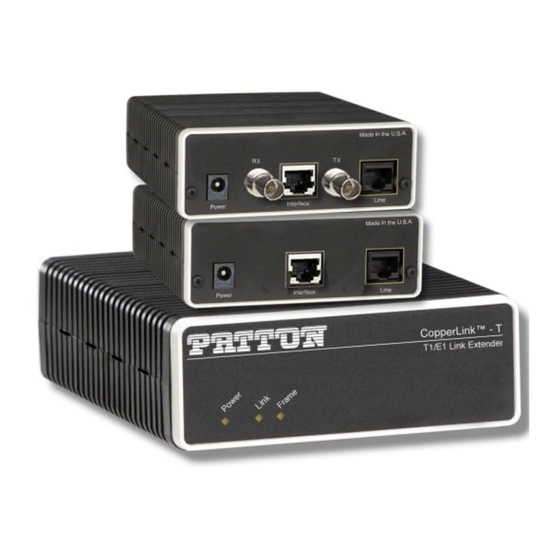
Summary of Contents for Patton electronics 2113
- Page 1 USER MANUAL MODELS 2113 & 2115 CopperLink™-T T1/E1 Extenders Part# 07M2113-UM SALES OFFICE Doc# 03331U2-001, (301) 975-1000 Rev. A TECHNICAL SUPPORT Revised 1/17/07 (301) 975-1007 An ISO-9001Certified Company...
-
Page 2: Table Of Contents
CONTENTS Warranty Information ..............4 Radio and TV Interference............4 CE Declaration of Conformity ............4 FCC Part 68.................. 5 Industry Canada Notice ..............5 Compliance................... 6 EMC....................6 Safety ................... 6 PSTN Regulatory................6 Service..................7 Alternate Patton support for Europe, Middle East, and Africa (EMEA) .................. - Page 3 Factory Default Dip Switch Configuration......18 B.1 Switch S1 - Factory Default configuration ........18 B.2 Switch S2 - Factory Default configuration ........18...
-
Page 4: Warranty Information
Under no condition shall Patton Electronics be liable for any damages incurred by the use of this product. These damages include, but are not limited to, the following: lost profits, lost savings and incidental or consequential damages arising... -
Page 5: Fcc Part 68
The safety advice in the documentation accompanying this product shall be obeyed. The conformity to the above directive is indicated by the CE sign on the device. 1.3 FCC PART 68 This equipment complies with Part 68 of FCC rules and the requirements adopted by ACTA. -
Page 6: Compliance
This Declaration of Conformity means that the equipment meets certain telecommunications network protective, operational and safety require- ments. The Department does not guarantee the equipment will operate to the user's satisfaction. Before installing this equipment, users should ensure that it is permissible to be connected to the facilities of the local telecommunications company. -
Page 7: Service
1.6 SERVICE All warranty and non-warranty repairs must be returned freight prepaid and insured to Patton Electronics. All returns must have a Return Materi- als Authorization number on the outside of the shipping container. This number may be obtained from Patton Electronics Technical Services at: •... -
Page 8: Safety When Working With Electricity
1.7 SAFETY WHEN WORKING WITH ELECTRICITY • This device contains no user serviceable parts. The equipment shall be returned to Patton Electronics for repairs, or repaired by qualified service personnel. • The external AC adaptor shall be a listed limited power source that incorporates a disconnect device and shall be positioned within easy reach of the operator. -
Page 9: General Information
2-wire T1/E1 extension connectivity to ISPs, PTTs, and enterprise environments using binder group friendly TC-PAM modulation. Line connection is made with an RJ-45 jack. Models 2113 and 2115 are powered by an 100/230 VAC (Universal) supply. The NTU features exter- nally-accessible DIP switches, loopback diagnostics, and CopperLink™-... -
Page 10: Installation
(Data to (120 Ohm) G.703/G.704 network) RX (75 Ohm) Power (Data from G.703/G.704 network) Figure 1. CopperLink-T Model 2113 rear panel i n t L i n Line r f a I n t e T1 interface (RJ-48C) Power Figure 2. CopperLink-T Model 2115 rear panel... -
Page 11: Connecting Power
3.1 CONNECTING POWER The external AC adaptor shall be a listed limited power source that incorporates a disconnect device and shall be positioned within easy reach of the operator. Ensure that the AC power cable meets all applicable standards CAUTION for the country in which it is to be installed, and that it is connected to a wall outlet which has earth ground. -
Page 12: Connecting The Line Port
3.4 CONNECTING THE CIRCUIT INTERFACE Your CopperLink-T comes with either an RJ-48C or an RJ-48C and dual BNC for connection to a T1 or E1: • Model 2113 - E1: 120-Ohm RJ-48C and dual 75-Ohm BNC connec- tors • Model 2115 - T1: RJ-48C To connect the twisted pair cable to the CopperLink-T serial port: 1. - Page 13 The unit marked as 2113/L or 2115/L is configured by Note default to accept timing from the T1/E1 circuit. The 2113/ R or 2115/L unit then recovers this timing from the line in order to ensure synchronization of the T1/E1 circuit over the extenders.
-
Page 14: Operation
LED status monitors. 4.1 FRONT PANEL LED STATUS MONITORS Models 2113 and 2115 feature three front-panel LEDs that monitor power, Ethernet signals, and the CopperLink connection. Figure 5 shows the front panel location of each LED. Table 1 describes the LED functions. -
Page 15: Configuration And Dip Switches
Refer to Appendix B on page 18 for the factory default dip switch configuration. Switch S1-7: Line Build Out Switch S1-7 defines the shape of the waveform on the T1 or E1 line. Table 2: S1-7 Default Position Switch 2113/L/EUI 2113/R/EUI 2115/L/EUI 2115/R/EUI S1-7 OFF (120) OFF (120) ON (0.0dB) -
Page 16: Specifications
• Model 2113 - 2.048 Mbps • Model 2115 - 1.544 Mbps A.2 CIRCUIT INTERFACE • E1 (Model 2113) presents G.703/G.704 interface. Either 75 Ohms (unbal- anced) or 120 Ohms (balanced). Pins 1 & 2 are Receive. Pins 4 & 5 are transmit. -
Page 17: Environmental
A.7 ENVIRONMENTAL • Temperature: 32–122°F (0–50°C) • Relative Humidity: 5–95%, non-condensing • Altitude: 0–15,000 ft (0–4,572 m) A.8 TRANSMISSION LINE • Single Twisted Pair A.9 LINE CODING • TC-PAM (Trellis Coded Pulse Amplitude Modulation) A.10 LINE INTERFACE • Transformer coupled, 2500 VRMS isolation A.11 LINE PHYSICAL CONNECTION •... -
Page 18: Factory Default Dip Switch Configuration
These settings should not be changed other than by instructions from Patton Support, lest the unit be rendered inoperable. B.1 SWITCH S1 - FACTORY DEFAULT CONFIGURATION Table 3: S1 Factory Default Dip Switch Configuration Switch 2113/L/EUI 2113/R/EUI 2115/L/EUI 2115/R/EUI Switch 1-1... - Page 19 NOTES _________________________________________________________ _________________________________________________________ _________________________________________________________ _________________________________________________________ _________________________________________________________ _________________________________________________________ _________________________________________________________ _________________________________________________________ _________________________________________________________ _________________________________________________________ _________________________________________________________ _________________________________________________________ _________________________________________________________ _________________________________________________________ _________________________________________________________ _________________________________________________________ _________________________________________________________ _________________________________________________________ _________________________________________________________ _________________________________________________________ _________________________________________________________ _________________________________________________________ _________________________________________________________ _________________________________________________________ _________________________________________________________...
- Page 20 NOTES _________________________________________________________ _________________________________________________________ _________________________________________________________ _________________________________________________________ _________________________________________________________ _________________________________________________________ _________________________________________________________ _________________________________________________________ _________________________________________________________ _________________________________________________________ _________________________________________________________ _________________________________________________________ _________________________________________________________ _________________________________________________________ _________________________________________________________ _________________________________________________________ _________________________________________________________ _________________________________________________________ _________________________________________________________ _________________________________________________________ _________________________________________________________ _________________________________________________________ Copyright © 2007 Patton Electronics Company All Rights Reserved.


Need help?
Do you have a question about the 2113 and is the answer not in the manual?
Questions and answers