Table of Contents
Advertisement
Advertisement
Table of Contents

Related Manuals for Asus P9D-M Series


Summary of Contents for Asus P9D-M Series
- Page 1 P9D-M Series...
- Page 2 Product warranty or service will not be extended if: (1) the product is repaired, modified or altered, unless such repair, modification of alteration is authorized in writing by ASUS; or (2) the serial number of the product is defaced or missing.
-
Page 3: Table Of Contents
Contents Contents ........................iii Notices ........................vii Safety information ....................viii About this guide ......................ix P9D-M Series Specifications Summary ..............xi Chapter 1: Product Introduction Welcome! ....................1-3 Package contents..................1-3 Serial number label ..................1-4 Special features..................1-4 1.4.1... - Page 4 Using the dual function power switch .......... 3-4 Chapter 4: BIOS setup Managing and updating your BIOS ............4-3 4.1.1 ASUS CrashFree BIOS 3 utility........... 4-3 4.1.2 ASUS Easy Flash Utility .............. 4-4 4.1.3 BUPDATER utility ................ 4-5 BIOS setup program .................. 4-7 4.2.1...
- Page 5 4.4.7 TPM................... 4-23 4.4.8 ACPI Settings ................4-23 4.4.9 WHEA Support ................4-24 4.4.10 NCT6779D Super IO Configuration .......... 4-24 4.4.11 Intel Server Platform Services ..........4-25 ® 4.4.12 Onboard LAN Configuration ............4-25 4.4.13 Serial Port Console Redirection ..........4-26 4.4.14 Runtime Error Logging Support ..........
- Page 6 Intel ® Rapid Storage Technology enterprise (Windows ® ) ..... 5-13 5.3.1 Creating a RAID set ..............5-14 5.3.2 Changing a Volume Type ............5-16 5.3.3 Deleting a volume ..............5-17 5.3.4 Preferences ................5-18 Chapter 6: Driver installation RAID driver installation ................6-3 6.1.1 Creating a RAID driver disk............
-
Page 7: Notices
If you require assistance, please call ASUS Customer Service at 1300 2787 88 or visit us at http://support.asus.com. -
Page 8: Safety Information
Safety information Electrical safety • To prevent electrical shock hazard, disconnect the power cable from the electrical outlet before relocating the system. • When adding or removing devices to or from the system, ensure that the power cables for the devices are unplugged before the signal cables are connected. If possible, disconnect all power cables from the existing system before you add a device. -
Page 9: About This Guide
Where to find more information Refer to the following sources for additional information and for product and software updates. ASUS websites The ASUS website provides updated information on ASUS hardware and software products. Refer to the ASUS contact information. Optional documentation Your product package may include optional documentation, such as warranty flyers, that may have been added by your dealer. -
Page 10: Conventions Used In This Guide
Conventions used in this guide To ensure that you perform certain tasks properly, take note of the following symbols used throughout this manual. DANGER/WARNING: Information to prevent injury to yourself when trying to complete a task. CAUTION: Information to prevent damage to the components when trying to complete a task IMPORTANT: Instructions that you MUST follow to complete a task. -
Page 11: P9D-M Series Specifications Summary
- 4 x SATA 3Gb/s ports - 2 x SATA 6Gb/s ports - Intel ® RSTe supports software RAID 0, 1, 10, & 5 (Windows ® * Refer to www.asus.com for the complete list of supported CPUs. (continued on the next page) - Page 12 P9D-M Series Specifications Summary Model Name P9D-M P9D-MV P9D-MX ® ® 2 x Intel I210AT controller 2 x Intel I210AT Networking 1 x Management LAN controller Aspeed Graphic Aspeed AST2300 32MB AST1300 64MB TPM Header 24-pin ATX power connector Connector...
- Page 13 P9D-M Series Specifications Summary Model Name P9D-M P9D-MV P9D-MX ASWM Enterprise Software Management ASMB7-iKVM for KVM-over-Internet Out of Band Solution Management (Optional) Temperature Monitoring FAN RPM Operation temperature: C – 35 C (50 F – 95 Non operation temperature: Environment C –...
-
Page 15: Chapter 1: Product Introduction
Chapter 1: Product Introduction... -
Page 16: Chapter Summary
Chapter summary This chapter describes the motherboard features and the new technology it supports. This chapter contains the following sections: Welcome! ....................1-3 Package contents..................1-3 Serial number label ..................1-4 Special features..................1-4 ASUS P9D-M... -
Page 17: Welcome
® The motherboard delivers a host of new features and latest technologies, making it another standout in the long line of ASUS quality motherboards! Before you start installing the motherboard and hardware devices on it, check the items in your package with the list below. -
Page 18: Serial Number Label
Serial number label Before requesting support from the ASUS Technical Support team, you must take note of the motherboard's serial number containing 12 characters xxS2xxxxxxxx as shown in the figure below. With the correct serial number of the product, ASUS Technical Support team members can then offer a quicker and satisfying solution to your problems. - Page 19 CPU temperature is monitored to prevent overheating and damage. System fan Rotations Per Minute (RPM) is monitored for timely failure detection. The chip monitors the voltage levels to ensure a stable supply of current for critical components. ASUS P9D-M Series...
-
Page 20: Innovative Asus Features
1.4.2 Innovative ASUS features ASUS Fan Speed technology The ASUS Fan Speed technology smartly adjusts the fan speeds according to the system loading to ensure quiet, cool, and efficient operation. Chapter 1: Product introduction... -
Page 21: Chapter 2: Hardware Information
Chapter 2: Hardware Information... - Page 22 This chapter contains the following sections: Before you proceed ................... 2-3 Motherboard overview ................2-4 Central Processing Unit (CPU) ..............2-8 System memory ..................2-14 Expansion slots..................2-16 Onboard LEDs ..................2-21 Jumpers ....................2-24 Connectors ....................2-28 ASUS P9D-M Series...
-
Page 23: Before You Proceed
Before you install or remove any component, ensure that the power supply is switched off or the power cord is detached from the power supply. Failure to do so may cause severe damage to the motherboard, peripherals, and/or components. ASUS P9D-M Series... -
Page 24: Motherboard Overview
Motherboard overview Before you install the motherboard, study the configuration of your chassis to ensure that the motherboard fits properly. To take advantage of all motherboard features, we highly recommend that you install it in an uATX 1.2 compliant chassis. Ensure to unplug the chassis power cord before installing or removing the motherboard. -
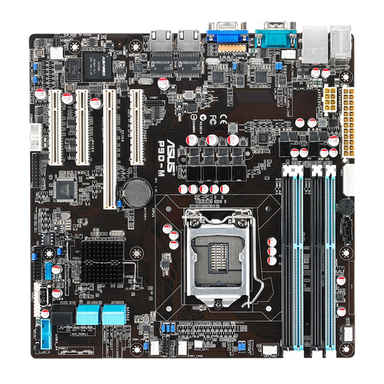
Page 25: Motherboard Layout
2.2.3 Motherboard layout P9D-M Motherboard Layout ASUS P9D-M Series... - Page 26 P9D-MV Motherboard Layout Chapter 2: Hardware information...
- Page 27 P9D-MX Motherboard Layout ASUS P9D-M Series...
-
Page 28: Layout Contents
2.2.4 Layout contents Slots/Sockets Page CPU sockets 2-10 DDR3 sockets 2-16 PCI Express x16 / PCI Express x8 2-18 Onboard LEDs Page Standby Power LED (SB_PWR1) 2-23 +5V Power LED (+5V_LED) 2-23 Location LED (LOC_LED1) 2-24 CPU Warning LED (ERR_CPU1) 2-24 Baseboard Management Controller LED (BMC_LED1) 2-25... - Page 29 2-36 Trusted Platform Module connector (20-1 pin TPM1) 2-36 4-pin power connector (4-pin PWR3) 2-37 ATX power connectors 2-37 (24-pin EATXPWR1, 8-pin EATX12V1) System panel connector (20-1 pin PANEL1) 2-38 Auxiliary panel connector (20-2 pin AUX_PANEL1) 2-39 ASUS P9D-M Series...
-
Page 30: Central Processing Unit (Cpu)
Contact your retailer immediately if the PnP cap is missing, or if you see any damage to the PnP cap/socket contacts/motherboard components. ASUS will shoulder the cost of repair only if the damage is shipment/ transit-related. - Page 31 The CPU fits in only one orientation. Gold DO NOT force the CPU into the triangle Alignment socket to prevent bending the pins on mark the socket and damaging the CPU. Alignment 2-11 ASUS P9D-M Series...
- Page 32 Close the load plate (A), ensuring that the front edge of the load plate Load lever slides under the retention lock (B) then push down the load lever (C). Retention lock Insert the load lever under the retention tab to remove the PnP cap from the CPU socket.
-
Page 33: Installing The Cpu Heatsink
Push down two fasteners at a time in a diagonal sequence to secure the heatsink and fan assembly in place. Orient the heatsink and fan assembly such that the CPU fan cable is closest to the CPU fan connector. 2-13 ASUS P9D-M Series... -
Page 34: Uninstalling The Cpu Heatsink And Fan
Connect the CPU fan cable to the connector on the motherboard labeled CPU_FAN1. DO NOT forget to connect the CPU fan connector! Hardware monitoring errors can occur if you fail to plug this connector. 2.3.3 Uninstalling the CPU heatsink and fan To uninstall the CPU heatsink and fan: Disconnect the CPU fan cable from the connector on the motherboard. -
Page 35: Installing The Cpu Heatsink In A Rack
• Ensure that the heatsink is not skewed or tilted, otherwise the CPU will overheat. • Do not overtighten the screws. Doing so can damage the CPU. 2-15 ASUS P9D-M Series... -
Page 36: System Memory
System memory 2.4.1 Overview The motherboard comes with four Double Data Rate 3 (DDR3) Dual Inline Memory Modules (DIMM) sockets. A DDR3 module has the same physical dimensions as a DDR2 DIMM but is notched differently to prevent installation on a DDR2 DIMM socket. DDR3 modules are developed for better performance with less power consumption. -
Page 37: Installing A Dimm On A Single Clip Dimm Socket
Press the retaining clip outward to unlock the DIMM. Remove the DIMM from the socket. Support the DIMM lightly with your fingers when pressing the retaining clips. The DIMM might get damaged when it pops out with extra force. 2-17 ASUS P9D-M Series... -
Page 38: Expansion Slots
Expansion slots In the future, you may need to install expansion cards. The following subsections describe the slots and the expansion cards that they support. Ensure to unplug the power cord before adding or removing expansion cards. Failure to do so may cause you physical injury and damage motherboard components. -
Page 39: Interrupt Assignments
ACPI Mode when used IRQ Holder for PCI Steering IRQ Holder for PCI Steering PS/2 Compatible Mouse Port Numeric Data Processor Primary IDE Channel Secondary IDE Channel * These IRQs are usually available for ISA or PCI devices. 2-19 ASUS P9D-M Series... -
Page 40: Pci Express X16 Slot (X8 Link)
2.5.4 PCI Express x16 slot (x8 link) The onboard PCIE 6 provides one x16 Gen3 link to CPU1. This slot supports VGA cards and various server class high performance add-on cards. 2.5.5 PCI Express x8 slot (x4 link) The onboard PCIE 5 and the PCIE 7 provides one x4 Gen3 link to CPU1. The onboard PCIE 4 provides one x4 Gen2 link to CPU1. -
Page 41: Connecting The Thermal Sensor Cable
Place the other end of the Thermal Sensor cable to the device you would like to monitor temperature. The motherboard illustration is for reference only. The motherboard layout and appearance may vary depending on the model, but the installation steps remain the same. 2-21 ASUS P9D-M Series... -
Page 42: Installing The Baseboard Management Card
2.5.7 Installing the Baseboard Management Card (P9D-M and P9D-MV models only) Follow the steps below to install an optional ASMB7 Management Card on your motherboard. Locate the Baseboard Management Card header on the motherboard. Orient and press the Management Card in place. The motherboard illustration is for reference only. -
Page 43: Onboard Leds
The illustration below shows the location of the onboard LED. +5V Power LED (+5V_LED1) This LED lights up when the Power-on button is pressed and the system is 2-23 ASUS P9D-M Series... - Page 44 Locator LED (LOCLED1) The Locator LED is a user-activated LED on the front of the server module that can be remotely turned on or off. It is used to find a specific server module within a chassis. CPU Warning LED (ERR_CPU1) The CPU warning LED lights up to indicate that a CPU error or failure has occurred.
- Page 45 Baseboard Management Controller LED (BMC_LED1)* The green heartbeat LED blinks per second to indicate that the ASMB7 is working normally. *P9D-M and P9D-MV models only. 2-25 ASUS P9D-M Series...
-
Page 46: Jumpers
Jumpers Clear RTC RAM (3-pin CLRTC1) This jumper allows you to clear the Real Time Clock (RTC) RAM in CMOS. You can clear the CMOS memory of date, time, and system setup parameters by erasing the CMOS RTC RAM data. The onboard button cell battery powers the RAM data in CMOS, which include system setup information such as system passwords. - Page 47 1–2 to activate the VGA feature. LAN controller setting (3-pin LAN_SW1, LAN_SW2) These jumpers allows you to enable or disable the onboard Intel I210AT ® Gigabit LAN controllers. Set to pins 1-2 to activate the Gigabit LAN feature. 2-27 ASUS P9D-M Series...
- Page 48 RAID configuration utility selection (3-pin RAID_SEL1) This jumper allows you to select the RAID configuration utility for creating disk arrays. Place the jumper caps over pins 1–2 if you want to use a Third- Party Setup Utility (default). Otherwise, place the jumper caps to pins 2–3 to use the Intel ®...
- Page 49 ME firmware force recovery setting (3-pin ME_RCVR1) This jumper allows you to force Intel Management Engine (ME) boot from recovery mode when ME become corrupted. VGA connector (16-1 pin VGA_HDR1) This connector supports VGA High Dynamic-Range interface HDR1. 2-29 ASUS P9D-M Series...
-
Page 50: Connectors
Connectors 2.8.1 Rear panel connectors PS/2 keyboard/mouse port (purple/green). This port is for a PS/2 keyboard or mouse. RJ-45 port for iKVM. This RJ-45 port functions only when you install an ASMB7 management card. P9D-M and P9D-MV models only. Serial port. This port connects a modem, or other devices that conform with serial specification. -
Page 51: Internal Connectors
If you installed Serial ATA hard disk drives, you can create a RAID 0, RAID 1, RAID 10, or RAID 5 configuration. The actual data transfer rate depends on the speed of Serial ATA hard disks installed. 2-31 ASUS P9D-M Series... - Page 52 P9D-MV • 7-pin SATA 6Gbps_1-2 connector [Light Blue]) • 7-pin SATA 3Gbps_3-6 connector [Black]) P9D-MX • 7-pin SATA 6Gbps_1-2 connector [Light Blue]) • 7-pin SATA 3Gbps_3-6 connector [Black]) The actual data transfer rate depends on the speed of Serial ATA hard disks installed. Chapter 2: Hardware information 2-32...
- Page 53 USB 2.0 connector (10-1 pin USB78, A-Type USB9) These connectors are for USB 2.0 ports. Connect the USB module cables to connectors USB78. These USB connectors comply with USB 2.0 specification that supports up to 480 Mbps connection speed. 2-33 ASUS P9D-M Series...
- Page 54 USB 3.0 connector (20-1 pin USB3_34)* These connectors allow you to connect a USB 3.0 module for additional USB 3.0 front or rear panel ports. With an installed USB 3.0 module, you can enjoy all the benefits of USB 3.0 including faster data transfer speeds of up to 5Gbps, faster charging time for USB-chargeable devices, optimized power efficiency, and backward compatibility with USB 2.0.
- Page 55 These are not jumpers! DO NOT place jumper caps on the fan connectors! • All fans feature the ASUS Smart Fan technology. Serial General Purpose Input/Output connector (6-1 pin SGPIO1) The SGPIO 1 connectors are used for the Intel Rapid Storage Technology Enterprise SGPIO interface that controls the LED pattern generation, device information, and general purpose data.
- Page 56 Serial port connectors (10-1 pin COM2) These connectors are for the serial COM2 port. Connect the serial port module cable to one of these connectors, then install the module to a slot opening at the back of the system chassis. Trusted Platform Module connector (20-1 pin TPM1) This connector supports a Trusted Platform Module (TPM) system, which can securely store keys, digital certificates, passwords, and data.
- Page 57 • This motherboard supports ATX2.0 PSU or later versions. • Ensure that your PSU can provide at least the minimum power required by your system. 2-37 ASUS P9D-M Series...
-
Page 58: System Panel Connector
12. System panel connector (20-1 pin PANEL1) This connector supports several chassis-mounted functions. 1. System power LED (3-pin PLED) This 3-pin connector is for the system power LED. Connect the chassis power LED cable to this connector. The system power LED lights up when you turn on the system power, and blinks when the system is in sleep mode. - Page 59 Connect the Locator LED cables to these 2-pin connector. The LEDs will light up when the Locator button is pressed. 5. Locator Button/Switch (2-pin AUX_BMCLOCBNT) These leads are for the locator button on the front panel. This button queries the state of the system locator. 2-39 ASUS P9D-M Series...
- Page 60 Chapter 2: Hardware information 2-40...
-
Page 61: Chapter 3: Powering Up
Chapter 3: Powering Up... - Page 62 Chapter summary This chapter describes the power up sequence, and ways of shutting down the system.This chapter contains the following sections: Starting up for the first time ..............3-3 Powering off the computer................ 3-4 ASUS P9D-M Series...
-
Page 63: Starting Up For The First Time
30 seconds from the time you turned on the power, the system may have failed a power-on test. Check the jumper settings and connections or call your retailer for assistance. At power on, hold down the <Del> key to enter the BIOS Setup. Follow the instructions in Chapter 4. ASUS P9D-M Series... -
Page 64: Powering Off The Computer
Powering off the computer 3.2.1 Using the OS shut down function Using Windows Server 2008 R2: ® Click the Start button, move the cursor to the triangle on the right of Log off, then click Shut Down. From the Shutdown Event Tracker, select the option that best describes why you want to shut down the computer. -
Page 65: Chapter 4: Bios Setup
Chapter 4: BIOS setup... - Page 66 BIOS setup program .................. 4-7 Main menu ....................4-10 Advanced menu ..................4-11 Event Logs menu ..................4-31 Boot menu ....................4-32 Monitor menu ................... 4-35 Security ..................... 4-36 Tool menu ....................4-39 4.10 Exit menu ....................4-39 ASUS P9D-M Series...
-
Page 67: Managing And Updating Your Bios
4.1.1 ASUS CrashFree BIOS 3 utility The ASUS CrashFree BIOS 3 is an auto recovery tool that allows you to restore the BIOS file when it fails or gets corrupted during the updating process. You can update a corrupted BIOS file using a USB flash drive that contains the updated BIOS file. -
Page 68: Asus Easy Flash Utility
4.1.2 ASUS Easy Flash Utility The ASUS Easy Flash Utility feature allows you to update the BIOS using a USB flash disk without having to use a DOS-based utility. Download the latest BIOS from the ASUS website at www.asus.com before using this utility. -
Page 69: Bupdater Utility
Updating the BIOS file To update the BIOS file using the BUPDATER utility: Visit the ASUS website at www.asus.com and download the latest BIOS file for the motherboard. Save the BIOS file to a bootable USB flash disk drive. Download the BUPDATER utility (BUPDATER.exe) from the ASUS support website at support.asus.com to the bootable USB flash disk drive you created earlier. - Page 70 The utility verifies the file, then starts updating the BIOS file. ASUSTek BIOS Update for DOS V1.06 (09/08/04) FLASH TYPE: MXIC 25L1605A Current ROM Update ROM BOARD: P9D-M BOARD: P9D-M VER: 0202 VER: 0212 DATE: 12/01/2012 DATE: 03/09/2013 PATH: WARNING! Do not turn off power during flash BIOS Note Writing BIOS: DO NOT shut down or reset the system while updating the BIOS to prevent system boot...
-
Page 71: Bios Setup Program
The BIOS setup screens shown in this section are for reference purposes only, and may not exactly match what you see on your screen. • Visit the ASUS website (www.asus.com) to download the latest BIOS file for this motherboard. ASUS P9D-M Series... -
Page 72: Bios Menu Screen
4.2.1 BIOS menu screen Menu items Menu bar Configuration fields General help Aptio Setup Utility - Copyright (C) 2013 American Megatrends, Inc. Main Advanced Event Logs Boot Monitor Security Tool Exit BIOS Information Set the Date, Use Tab to BIOS Vendor American Megatrends switch between Data elements. -
Page 73: Menu Items
A scroll bar appears on the right side of a menu screen when there are items that do not fit on the screen. Press the Up/Down arrow keys or <Page Up> /<Page Down> keys to display the other items on the screen. ASUS P9D-M Series... -
Page 74: Main Menu
Main menu When you enter the BIOS Setup program, the Main menu screen appears. The Main menu provides you an overview of the basic system information, and allows you to set the system date and time. Aptio Setup Utility - Copyright (C) 2012 American Megatrends, Inc. Main Advanced Event Logs... -
Page 75: Advanced Menu
Serial Port Console Redirection NCT6779D Super IO Configuration Intel Server Platform Services Network Stack Intel RC Drivers Version Details Onboard LAN Configuration Serial Port Console Redirection Runtime Error Logging Network Stack Intel RC Drivers Version Detail ASUS P9D-M Series 4-11... -
Page 76: Cpu Configuration
4.4.1 CPU Configuration The items in this menu show the CPU-related information that the BIOS automatically detects. Some items may not appear if your CPU does not support the related functions. Aptio Setup Utility - Copyright (C) 2013 American Megatrends, Inc. Advanced Enabled for WIndows XP and CPU Configuration... - Page 77 This item appears only when you set the EIST item to [Enabled]. This allows you to enable or disable the Intel Turbo Mode Technology. ® Configuration options: [Enabled] [Disabled] Energy Performance [Performance] Allows you to optimize between performance and power savings. Configuration options: [Performance] [Balanced Performance] [Balanced Energy] [Energy Efficient] ASUS P9D-M Series 4-13...
- Page 78 CPU C states [Enabled] Allows you to enable or disable the CPU C states. Configuration options: [Enabled] [Disabled] This following items appears only when you set the CPU C states to [Enabled]. Enhanced C1 State [Enabled] This item allows you to enable or disable the Enhanced C1 state. Configuration options: [Enabled] [Disabled] CPU C3 Report [Enabled] Allows you to enable or disable the CPU C3 report to OS.
- Page 79 Intel TXT (LT) Suppot [Disabled] Allows you to enable or disable the Intel TXT (LT) support. Configuration options: [Disabled] [Enabled] ACPI T State [Enabled] Allows you to enable or disable the ACPI T state. Configuration options: [Disabled] [Enabled] ASUS P9D-M Series 4-15...
-
Page 80: Pch-Io Configuration
4.4.2 PCH-IO Configuration Allows you to configure PCH parameters. Aptio Setup Utility - Copyright (C) 2013 American Megatrends, Inc. Advanced U S B C o n f i g u r a t i o n Intel PCH RC Version 1.3.0.0 settings. -
Page 81: Sata Configuration
S.M.A.R.T. Status Check [Enabled] Self-Monitoring, Analysis, and Reporting Technology (S.M.A.R.T.) is a monitor system. When read/write of your hard disk errors occur, this feature allows the hard disk to report warning messages during the POST. Configuration options: [Enabled] [Disabled] ASUS P9D-M Series 4-17... -
Page 82: System Agent (Sa) Configuration
Serial SATA Port 4 HardDisk (250.0GB) Software Preserve SUPPORTED Serial SATA Port 5 ASUS DVD-E8 ATAPI Software Preserve SUPPORTED 4.4.4 System Agent (SA) Configuration This allows you to change System Agent parameters. Aptio Setup Utility - Copyright (C) 2013 American Megatrends, Inc. -
Page 83: Memory Configuration
Memory Remap [Enabled] This allows you to enable or disable the Memory Remap above 4G. Configuration options: [Enabled] [Disabled] GDXC Support [Disabled] This allows you to enable or disable the GDXC feature. Configuration options: [Enabled] [Disabled] ASUS P9D-M Series 4-19... -
Page 84: 4.4.5 Pci Subsystem Settings
4.4.5 PCI Subsystem Settings Allows you to configure PCI-X and PCI Express Settings. Aptio Setup Utility - Copyright (C) 2013 American Megatrends, Inc. Advanced Change PCI Express PCI Bus Driver Version V 2.05.02 Devices Settings. PCI 64bit Resources Handling Above 4G Decoding [Disabled] PCI Common Settings Load RT32 Image... -
Page 85: 4.4.6 Usb Configuration
USB hardware delays and time-outs: USB transfer time-out [20 sec] Device reset time-out [20 sec] Device power-up delay [Auto] The USB Devices item shows the auto-detected values. If no USB device is detected, the item shows None. ASUS P9D-M Series 4-21... - Page 86 Legacy USB Support [Enabled] Allows you to enable or disable the support for legacy USB devices. Setting to [Auto] allows the system to detect the presence of USB devices at startup. If detected, the USB controller legacy mode is enabled. If no USB device is detected, the legacy USB support is disabled. Configuration options: [Disabled] [Enabled] [Auto] USB3.0 Support [Enabled] Enables or disables the USB3.0 (XHCI) controller support.
-
Page 87: Tpm
ACPI Sleep State [Both S1 and S3 available for OS to choose from] Allows you to set the ACPI Sleep state. Configuration options: [Suspend Disabled] [S1 only (CPU Stop Clock)] [S3 only (Suspend to RAM)] [Both S1 and S3 available for OS to choose from] ASUS P9D-M Series 4-23... -
Page 88: Whea Support
4.4.9 WHEA Support Aptio Setup Utility - Copyright (C) 2013 American Megatrends, Inc. Advanced Enables or disable WHEA Support [Enabled] Windows Hardware Error Architecture. WHEA [Enabled] Allows you to enable or disable the Windows ® Hardware Error Architecture (WHEA) support. Configuration options: [Disabled] [Enabled] 4.4.10 NCT6779D Super IO Configuration... -
Page 89: Intel ® Server Platform Services
Allows you to enable or disable the INTEL I210 LAN function in the system. Configuration Options: [Enabled] [Disabled] INTEL I210 LAN1 - LAN2 OpROM Allows you to launch the Intel I210 LAN OpROM. Configuration options: [Disabled] [PXE] [iSCSI] ASUS P9D-M Series 4-25... -
Page 90: Serial Port Console Redirection
4.4.13 Serial Port Console Redirection Aptio Setup Utility - Copyright (C) 2012 American Megatrends, Inc. Advanced Console Redirection COM1 Enable or Disable. Console Redirection [Disabled] Console Redirection Settings COM2 Console Redirection [Enabled] Console Redirection Settings Serial Port for Out-of-Band Management/ Windows Emergency Management Services (EMS) Console Redirection [Disabled]... - Page 91 Configuration options: [VT100] ASCII char set. [VT100+] Extends VT100 to support color, function keys, et. [VT-UTF8] Uses UTF8 encoding to map Unicode chars onto 1 or more bytes [ANSI] Extended ASCII char set ASUS P9D-M Series 4-27...
-
Page 92: Runtime Error Logging Support
Bits per second [115200] This item only appears when you set the Console Redirection to [Enabled]. Selects serial port transmission speed. The speed must be matched on the other side. Long or noisy lines may require lower speeds. Configuration options: [9600] [19200] [38400] [57600] [115200] Flow Control [None] This item only appears when you set the Console Redirection to [Enabled]. -
Page 93: Network Stack
This item displays the Version String for the Intel RC Drivers. ® Aptio Setup Utility - Copyright (C) 2013 American Megatrends, Inc. Advanced Intel CPU RC Version 1.3.0.0 Memory RC Version 1.3.0.0 Intel SA RC Version 1.3.0.0 Intel PCH RC Version 1.3.0.0 ASUS P9D-M Series 4-29... -
Page 94: Event Logs Menu
Event Logs menu The Event Logs menu items allow you to change the event log settings and view the system event logs. Aptio Setup Utility - Copyright (C) 2013 American Megatrends, Inc. Main Advanced Event Logs Boot Monitor Security Tool Exit Event Logs Change Smbios Event Log Settings... -
Page 95: Boot Menu
Allows you to enable or disable the full screen logo display feature. Configuration options: [Disabled] [Enabled] Set this item to [Enabled] to use the ASUS MyLogo2™ feature. GateA20 Active [Upon Request] This item is useful when any RT code is execute above 1MB. When set to [Upon Request], the GA20 can be disabled using BIOS services. -
Page 96: Boot Option Priorities
These items specify the boot device priority sequence from the available devices. The number of device items that appears on the screen depends on the number of devices installed in the system. • To select the boot device during system startup, press <F8> when ASUS Logo appears. ® •... - Page 97 Configuration options: [Do not launch] [UEFI only] [Legacy only] [Legacy first] [UEFI first] Other PCI device ROM priority [Legacy OpROM] This option allows you to control the execution of UEFI and Legacy Storage OpROM. Configuration options: [UEFI OpROM] [Legacy OpROM] ASUS P9D-M Series 4-33...
-
Page 98: Monitor Menu
The onboard hardware monitor automatically detects the voltage output through the onboard voltage regulators. Fan Speed Control [Generic Mode] Allows you to configure the ASUS Smart Fan feature that smartly adjusts the fan speeds for more efficient system operation. Configuration options: [Low Speed Mode] [Generic Mode] [High Speed Mode] [Full Speed... -
Page 99: Security
From the Create New Password box, key in a new password, then press <Enter>. Confirm the password when prompted. To clear the administrator password, follow the same steps as in changing an administrator password, but press <Enter> when prompted to create/confirm the password. ASUS P9D-M Series 4-35... -
Page 100: User Password
User Password To set a user password: Select the User Password item and press <Enter>. From the Create New Password box, key in a password, then press <Enter>. Confirm the password when prompted. To change a user password: Select the User Password item and press <Enter>. From the Enter Current Password box, key in the current password, then press <Enter>. - Page 101 This item will ask you if you want to Install Factory Default secure variables. Select Yes if you want to load the default secure variables, otherwise select No. Platform Key (PK)/Key Exchange Key Database (KEK)/Authorized Signature Database (DB)/ Forbidden Signature Database (DBX) Configuration options: [Set New] [Delete] [Append] ASUS P9D-M Series 4-37...
-
Page 102: Tool Menu
BIOS. Start EzFlash utility Allows you to run the Start EzFlash utility. For more information, see section 4.1.2 ASUS EzFlash utility. 4.10 Exit menu The Exit menu items allow you to save or discard your changes to the BIOS items. -
Page 103: Restore Defaults
Launch EFI Shell from filesystem device This option allows you to launch the EFI Shell application (shellx64.efi) from one of the available filesystem devices. Select Yes to proceed, or No to cancel, and then press <Enter>. ASUS P9D-M Series 4-39... - Page 104 4-40 Chapter 4: BIOS setup...
-
Page 105: Chapter 5: Raid Configuration
Chapter 5: RAID Configuration... - Page 106 This chapter provides instructions for setting up, creating, and configuring RAID sets using the available utilities. This chapter contains the following sections: Setting up RAID ..................5-3 Intel Rapid Storage Technology Enterprise Option ROM Utility ..5-5 ® Intel Rapid Storage Technology enterprise (Windows ) ..... 5-13 ® ® ASUS P9D-M Series...
-
Page 107: Setting Up Raid
If you want to boot the system from a hard disk drive included in a created RAID set, copy the RAID driver first from the support DVD to a floppy disk before you install an operating system to the selected hard disk drive. ASUS P9D-M Series... -
Page 108: Installing Hard Disk Drives
5.1.5 RAID configuration utilities Depending on the RAID connectors that you use, you can create a RAID set using the utilities embedded on each RAID controller. The P9D-M Series motherboards support Intel Rapid ® Storage Technology for setting up RAID. -
Page 109: Intel
The navigation keys at the bottom of the screen allow you to move through the menus and select the menu options. The RAID BIOS setup screens shown in this section are for reference only and may not exactly match the items on your screen. ASUS P9D-M Series... -
Page 110: Creating A Raid Set
5.2.1 Creating a RAID set To create a RAID set: From the utility main menu, select 1. Create RAID Volume and press <Enter>. Key in a name for the RAID set and press <Enter>. Intel(R) Rapid Storage Technology enterprise - SATA Option ROM - 3.6.0.1023 Copyright(C) 2003-12 Intel Corporation. - Page 111 From the following warning message, press <Y> to create the RAID volume and return to the main menu, or press <N> to go back to the CREATE VOLUME menu WARNING: ALL DATA ON SELECTED DISKS WILL BE LOST. Are you sure you want to create this volume? (Y/N): ASUS P9D-M Series...
-
Page 112: Deleting A Raid Set
5.2.2 Deleting a RAID set Take caution when deleting a RAID set. You will lose all data on the hard disk drives when you delete a RAID set. To delete a RAID set: From the utility main menu, select 2. Delete RAID Volume and press <Enter>. From the Delete Volume Menu, press the up/down arrow keys to select the RAID set you want to delete then press <Del>. -
Page 113: Resetting Disks To Non-Raid
Member Disk ST3300656SS 37VN00009846RAJ1 279.3GB Member Disk Select the disks that should be reset. ]-Previous/Next [SPACE]-Selects [ENTER]-Selection Complete Press <Y> in the confirmation window to reset the drive(s) or press <N> to return to the utility main menu. ASUS P9D-M Series... -
Page 114: Rebuilding The Raid
5.2.4 Exiting the Intel Rapid Storage Technology enterprise ® SATA Option ROM utility To exit the utility: From the utility main menu, select 4. Exit then press <Enter>. From the following warning message, press <Y> to exit or press <N> to return to the utility main menu. - Page 115 Remove the failed SATA hard disk and install a new SATA hard disk of the same specification into the same SATA Port. Select a destination disk with the same size as the original hard disk. Reboot the system then follow the steps in section Rebuilding the RAID with another non-RAID disk. ASUS P9D-M Series 5-11...
-
Page 116: Setting The Boot Array In The Bios Setup Utility
5.2.6 Setting the Boot array in the BIOS Setup Utility You can set the boot priority sequence in the BIOS for your RAID arrays when setting up multi-RAID using the Intel Rapid Storage Technology enterprise Option ROM utililty. ® To set the boot array in the BIOS: Set at least one of the arrays bootable to boot from the hard disk. -
Page 117: Intel ® Rapid Storage Technology Enterprise (Windows ® )
Your storage system is configured for data protection, increased performance and optimal data storage capacity. You can create additional volumes to further optimize your storage system. You can click Rescan to re-scan any attached hard disks. ASUS P9D-M Series 5-13... -
Page 118: Creating A Raid Set
5.3.1 Creating a RAID set To create a RAID set: From the utility main menu, select Create Volume then select volume type and click Next. Key in a name for the RAID set, then select the array disks. Select the Volume Size tab then drag the bar to set the volume size. Click Next. - Page 119 You still need to partition your new volume using Windows Disk Management before adding any data. The created RAID set is displayed in the Volumes list. If you wish to change the settings, go to Volume Properties. ASUS P9D-M Series 5-15...
-
Page 120: Changing A Volume Type
5.3.2 Changing a Volume Type To change the volume type in Volume Properties: Click the SATA array items you want to change in the Volumes field. From the Volume Properties field, select Type:RAID 1 Change type. You can also change the Name, Select the new volume type, and Select additional disks to include in the new volume if needed. -
Page 121: Deleting A Volume
From the Volumes field in the utility main menu, select the volume that you want to delete. From the Volume Properties field, select Delete volume. Click Yes to delete the volume and return to the utility main menu, or click No to return to the main menu. ASUS P9D-M Series 5-17... -
Page 122: Preferences
5.3.4 Preferences System Preferences Allows you to configure displayed storage system notifications. E-Mail Preferences Allows you to setup e-mail notifications for the following storage system events: • Storage system information • Storage system warnings • Storage system errors 5-18 Chapter 5: RAID configuration... -
Page 123: Chapter 6: Driver Installation
Chapter 6: Driver installation... - Page 124 Running the Support DVD ................ 6-8 Installing the LAN driver................6-16 Installing the VGA driver ................. 6-21 Installing the Intel C22x MEI NULL HECI driver ........6-24 ® Installing the Intel I210 Gigabit Adapter driver ........6-26 ® ASUS P9D-M Series...
-
Page 125: Raid Driver Installation
From the C22x Intel RAID Driver sub-menu, use the Up or Down arrow keys to select the driver and press <Enter> to create the RAID driver disk. C22x INTEL RAID Driver C22x INTEL RAID Driver Windows 32 bit(AHCI / AHCI RAID) Windows Server 2012 64 bit (AHCI / AHCI RAID) Back Exit ASUS P9D-M Series... - Page 126 Select YES from the following warning message then press <Enter>. WARNING !!! ALL DATA ON THE FLOPPY DISKETTE WILL BE DELETED !! DO YOU WANT TO CONTINUE ? On the following Important message, select YES if an ASMB7 is installed, otherwise select NO, then press <Enter>.
-
Page 127: Installing The Raid Controller Driver
® Boot the computer using the Windows Server 2008 OS installation disc. Follow the screen ® instructions to start installing Windows Server 2008. When prompted to choose a type of installation, click Custom (advanced). Click Load Driver. ASUS P9D-M Series... - Page 128 A message appears reminding you to insert the installation media containing the driver of the RAID controller driver. If you have only one optical drive installed in your system, eject the Windows OS installation disc and replace with the motherboard Support DVD in the optical drive.
-
Page 129: Management Applications And Utilities Installation
• The contents of the support DVD are subject to change at any time without notice. Visit the ASUS website (www.asus.com) for the latest updates on software and utilities. • The DVD is supported on Windows Server 2008 R2 and Windows Server 2012. - Page 130 6.3.1 Drivers menu tab The Drivers Menu shows the available device drivers if the system detects installed devices. Install the necessary drivers to activate the devices. 6.3.2 Utilities menu tab The Utilities menu displays the software applications and utilities that the motherboard supports.
-
Page 131: Manual Menu
MakeDisk menu. 6.3.4 Manual menu The Manual menu provides the link to the Broadcom NetXtreme II Network Adapter user guide. You need an Internet browser installed in your OS to view the User Guide. ASUS P9D-M Series... - Page 132 6.3.5 Contact information menu The Contact tab displays the ASUS contact information, e-mail addresses, and useful links if you need more information or technical support for your motherboard. This information can also be found on the inside front cover of this user guide.
- Page 133 Chipset Device Software ® appears. Click Next to start the installation. Select Yes to accept the terms in the License Agreement window to continue the process. Read the Readme File information and click Next to continue. ASUS P9D-M Series 6-11...
- Page 134 Click Install in the Windows Security window. The Windows Security window may appear more than once and you may have to click Install several times to continue with the installation. When finished, click Next. When prompted to restart the computer, select Yes, I want to restart this computer now then click Finish to complete the installation.
- Page 135 DVD. Click Intel Chipset Device Software from the Drivers menu to start the installation. ® From the Intel Chipset Device Software, ® click Next. In the License Agreement window, click Yes to continue the process. ASUS P9D-M Series 6-13...
- Page 136 Read the Readme File information and click Next to continue. When done, click Finish to complete the installation. 6-14 Chapter 6: Driver installation...
-
Page 137: Installing The Lan Driver
ASSETUP.EXE from the BIN folder. Double-click the ASSETUP.EXE to run the support DVD. Click Intel Network Connections ® Software on the Drivers menu to start the installation. From the Intel Network Connections ® window, click Install Drivers and Software. ASUS P9D-M Series 6-15... - Page 138 Click Next in the Welcome to the InstallShield Wizard for Intel(R) Network Connections. From the License Agreement window, select I accept the terms in the license agreement then click Next. Select the drivers you want to install in the Setup Options window and click Next. From the Ready to Install the Program window, click Install.
- Page 139 If Autorun is NOT enabled in your computer, browse the contents of the support DVD to locate the file ASSETUP.EXE from the BIN folder. Double-click the ASSETUP.EXE to run the support DVD. Click Intel Network Connections Software on the Drivers menu to start the ® installation. ASUS P9D-M Series 6-17...
- Page 140 From the Intel Network Connections ® window, click Install Drivers and Software. Click Next in the Welcome to the InstallShield Wizard for Intel(R) Network Connections window. Select the drivers you want to install in the Setup Options window and click Next. 6-18 Chapter 6: Driver installation...
- Page 141 Click Install to continue. When done, click Finish to complete the installation. ASUS P9D-M Series 6-19...
-
Page 142: Installing The Vga Driver
Installing the VGA driver This section provides instructions on installing the ASPEED Video Graphics Adapter (VGA) driver. To install the ASPEED VGA driver on Windows Server 2008 R2: ® Restart the computer. Log in with Administrator privileges. Insert the Motherboard Support DVD in the optical drive. The support DVD automatically displays the Drivers menu if Autorun is enabled in your computer. - Page 143 Key in a username and organization then click Next. Select Complete in the Setup Type window then click Next. Click Install to begin the installation. When done, click Finish. ASUS P9D-M Series 6-21...
- Page 144 When prompted to restart the computer, click Yes. To install the ASPEED VGA driver on Windows Server 2012: ® Restart the computer. Log in with Administrator privileges. Insert the Motherboard Support DVD to the optical drive. The support DVD automatically displays the Drivers menu if Autorun is enabled in your computer.
-
Page 145: Installing The Intel ® C22X Mei Null Heci Driver
C22x MEI NULL HECI on the ® Drivers menu of the main screen to start the installation. From the Welcome to the Setup Program window, click Next. Click Yes in the License Agreement window to continue with the installation. ASUS P9D-M Series 6-23... - Page 146 Click NEXT when the installation of driver is complete. Click Finish to complete the installation. 6-24 Chapter 6: Driver installation...
-
Page 147: Installing The Intel ® I210 Gigabit Adapter Driver
ASSETUP.EXE from the BIN folder. Double-click the ASSETUP.EXE to run the support DVD. Click Intel® I210 Gigabit Adapter Driver in the Drivers menu of the main screen to start the installation. Click Next to continue. From the Program Maintenance window, select Modify then click Next. ASUS P9D-M Series 6-25... - Page 148 Select the options you want to install then click Next to continue. Click Install in the Ready to Modify the Program window to begin with the loading of the selected options. When done, click Finish. 6-26 Chapter 6: Driver installation...
- Page 149 Click Intel® I210 Gigabit Adapter Driver in the Drivers menu of the main screen to start the installation. Click Next to continue. From the Program Maintenance window, select Modify then click Next. Select the options you want to install then click Next to continue. ASUS P9D-M Series 6-27...
- Page 150 In the Ready to Modify the Program window, click Install to load the options you selected. When done, click Finish. 6-28 Chapter 6: Driver installation...
-
Page 151: Appendix A: Reference Information
Appendix A: Reference Information... - Page 152 Chapter summary This appendix includes additional information that you may refer to when configuring the motherboard. This chapter contains the following sections: P9D-M block diagram................A-3 P9D-MV block diagram ................A-3 P9D-MX block diagram ................A-4 ASUS P9D-M Series...
-
Page 153: P9D-M Block Diagram
P9D-M block diagram P9D-MV block diagram ASUS P9D-M Series... -
Page 154: P9D-Mx Block Diagram
P9D-MX block diagram Appendix A: Reference information... - Page 155 ASUS P9D-M Series...
- Page 156 Appendix A: Reference information...
Need help?
Do you have a question about the P9D-M Series and is the answer not in the manual?
Questions and answers