Table of Contents
Advertisement
Advertisement
Table of Contents

Related Manuals for Asus P9D WS


Summary of Contents for Asus P9D WS
- Page 1 P9D WS...
- Page 2 Product warranty or service will not be extended if: (1) the product is repaired, modified or altered, unless such repair, modification of alteration is authorized in writing by ASUS; or (2) the serial number of the product is defaced or missing.
-
Page 3: Table Of Contents
Contents Notices ........................vi Safety information ..................... vii About this guide ....................... viii P9D WS specifications summary ................x Chapter 1: Product introduction Welcome! ....................1-1 Package contents..................1-1 Special features..................1-2 1.3.1 Product highlights................ 1-2 1.3.2 ASUS Workstation Exclusive Features ........1-3 1.3.3... - Page 4 3.6.9 Network Stack ................3-38 Monitor menu ................... 3-39 Boot menu ....................3-42 Tools menu ....................3-48 3.9.1 ASUS EZ Flash 2 Utility ............3-48 3.9.2 ASUS O.C. Profile ..............3-48 3.9.3 ASUS SPD Information ............. 3-49 3.10 Exit menu ....................3-50 3.11...
- Page 5 Contents 4.3.3 EPU ..................... 4-7 4.3.4 Fan Xpert 2 ................. 4-8 4.3.5 USB 3.0 Boost................4-10 4.3.6 EZ Update ................. 4-11 4.3.7 Network iControl................ 4-12 4.3.8 System Information ..............4-14 4.3.9 USB BIOS Flashback ..............4-16 4.3.10 USB Charger+ ................4-17 4.3.11 Audio configurations..............
-
Page 6: Notices
Complying with the REACH (Registration, Evaluation, Authorisation, and Restriction of Chemicals) regulatory framework, we published the chemical substances in our products at ASUS REACH website at http://csr.asus.com/english/REACH.htm. DO NOT throw the motherboard in municipal waste. This product has been designed to enable proper reuse of parts and recycling. -
Page 7: Safety Information
Safety information Electrical safety • To prevent electrical shock hazard, disconnect the power cable from the electrical outlet before relocating the system. • When adding or removing devices to or from the system, ensure that the power cables for the devices are unplugged before the signal cables are connected. If possible, disconnect all power cables from the existing system before you add a device. -
Page 8: About This Guide
Where to find more information Refer to the following sources for additional information and for product and software updates. ASUS websites The ASUS website provides updated information on ASUS hardware and software products. Refer to the ASUS contact information. Optional documentation Your product package may include optional documentation, such as warranty flyers, that may have been added by your dealer. -
Page 9: Conventions Used In This Guide
Conventions used in this guide To ensure that you perform certain tasks properly, take note of the following symbols used throughout this manual. DANGER/WARNING: Information to prevent injury to yourself when trying to complete a task. CAUTION: Information to prevent damage to the components when trying to complete a task. -
Page 10: P9D Ws Specifications Summary
Dual-channel architecture Supports Intel Extreme Memory Profile (XMP) ® **Refer to www.asus.com or this user manual for the Memory QVL (Qualified Vendors Lidts) Expansion 1 x PCIe 3.0 x16 (at x16 or x8) slots 1 x PCIe 3.0 x16 (at x8 or x4) 1 x PCIe 3.0 x16 (at x4) - Page 11 - Network iControl - MemOK! - AI Suite III - Anti Surge - ASUS EFI BIOS EZ Mode featuring friendly graphics user interface ASUS Quiet Thermal Solution: - ASUS Fanless Design: Heat-sink solution - ASUS Fan Xpert II ASUS EZ DIY:...
- Page 12 P9D WS specifications summary Internal I/O 1 x USB 3.0/2.0 connector supports additional 2 USB ports (19-pin) connectors 2 x USB 2.0/1.1 connectors support additional 2 USB ports 1 x USB 2.0/1.1 vertical ports 24-pin ATX Power connector 8-pin ATX +12V Power connector...
-
Page 13: Chapter 1: Product Introduction
® The motherboard delivers a host of new features and latest technologies, making it another standout in the long line of ASUS quality motherboards! Before you start installing the motherboard, and hardware devices on it, check the items in your package with the list below. -
Page 14: Special Features
This motherboard complies with the European Union’s Energy-related Products (ErP) requirements, which requires products to meet certain energy efficiency criteria for energy consumption. This in in keeping with ASUS’ vision of creating environment-friendly and energy-efficient products to reduce a product’s carbon footprint and reduce its environmental impact. -
Page 15: Asus Workstation Exclusive Features
Users can count on up to 4 Tesla cards with Haswell CPU which is built with on-board graphic chipset, that are plugged into P9D WS for intensive parallel computing on tons of data, which delivers nearly 4 teraflops of performance. It is the best choice to work as a personal supercomputer on your desk instead of a computer cluster in a room. -
Page 16: Asus Features
The bundled G.P. Diagnosis card double-checks the system quickly provides precise information everytime you turn on your computer. 3 Independent Displays Without extra VGA card needed, the P9D WS gives users ability to multitask on up to three independent displays through DisplayPort, HDMI and DVI-I connectors. ASUS Doctor Power ASUS Doctor Power is an ensemble of LEDs, switches, and application that automatically detects and diagnoses related issues regarding your power supply unit (PSU). -
Page 17: Asus Ez Diy
ASUS EZ Flash 2 ASUS EZ Flash 2 is a user-friendly utility that allows you to update the BIOS without using a bootable floppy disk or an OS-based utility. -
Page 18: Asus Crystal Sound
ASUS CrashFree BIOS 3 ASUS CrashFree BIOS 3 allows you to restore a corrupted BIOS file from a USB storage device containing the BIOS file. IEEE 1394a interface IEEE 1394a interface provides high speed digital interface for audio/video devices such as digital television, digital video camcorders, storage peripherals and other portable devices. -
Page 19: Chapter 2: Hardware Information
Before you install or remove any component, ensure that the ATX power supply is switched off or the power cord is detached from the power supply. Failure to do so may cause severe damage to the motherboard, peripherals, or components. ASUS P9D WS... -
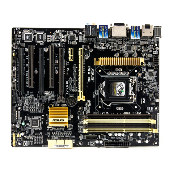
Page 20: Motherboard Overview
Motherboard overview 2.2.1 Motherboard layout Refer to 2.2.8 Internal connectors and 2.3.10 Rear panel connection for more information about rear panel connectors and internal connectors. Chapter 2: Hardware information... -
Page 21: Layout Contents
CPU, chassis, and power fan connectors (4-pin CPU_FAN, 2-27 4-pin CHA_FAN1-4) DDR3 DIMM slots MemOK! switch 2-15 USB 3.0 connector (20-1 pin USB3_12) 2-25 ASUS Dr. POWER switch 2-13 Intel C226 Serial ATA 6.0 Gb/s connectors 2-23 ® (7-pin SATA6G_1-6 [yellow]) DirectKey button... -
Page 22: Central Processing Unit (Cpu)
Contact your retailer immediately if the PnP cap is missing, or if you see any damage to the PnP cap/socket contacts/motherboard components. ASUS will shoulder the cost of repair only if the damage is shipment/ transit-related. -
Page 23: System Memory
The motherboard comes with four Double Data Rate 3 (DDR3) Dual Inline Memory Modules (DIMM) slots. A DDR3 module is notched differently from a DDR or DDR2 module. DO NOT install a DDR or DDR2 memory module to the DDR3 slot. Recommended memory configurations ASUS P9D WS... -
Page 24: Memory Configurations
(Memory chip capacity counts in Megabit, 8 Megabit/Mb = 1 Megabyte/MB). For system stability, use a more efficient memory cooling system to support a full memory load (4 DIMMs) or overclocking condition. P9D WS Motherboard Qualified Vendors Lists (QVL) • ASUS exclusively provides hyper DIMM support function. - Page 25 P9D WS Motherboard Qualified Vendors Lists (QVL) DDR3 1600 MHz capability Vendors Part No. Size Chip Chip NO. Timing Voltage DIMM Brand socket support (Optional) A-DATA AD3U1600C2G11 MICRON D9PFJ 11-11-11-28 • • A-DATA AD3U1600C4G11 MICRON D9PFJ 11-11-11-28 • • A-DATA...
- Page 26 P9D WS Motherboard Qualified Vendors Lists (QVL) DDR3 1600 MHz capability Vendors Part No. Size Chip Chip NO. Timing Voltage DIMM Brand socket support (Optional) G.SKILL F3-12800CL7D-8GBRH 8GB ( 2x 4GB ) 7-8-7-24 • • (XMP) G.SKILL F3-12800CL7Q-16GBXH 16GB ( 4x 4GB ) DS 7-8-7-24 •...
- Page 27 P9D WS Motherboard Qualified Vendors Lists (QVL) DDR3 1600 MHz capability Vendors Part No. Size Chip Brand Chip NO. Timing Voltage DIMM socket support (Optional) SanMax SMD-4G68NG-16KK ELPIDA J2108BDBG-GN-F • • Silicon SP002GBLTU160V02(XMP) S-POWER 20YT5NG 9-11-11-28 • • Power Silicon...
- Page 28 P9D WS Motherboard Qualified Vendors Lists (QVL) DDR3 1333 MHz capability Vendors Part No. Size Chip Brand Chip NO. Timing Voltage DIMM socket support (Optional) G.SKILL F3-10666CL9D-8GBXL 8GB ( 2x 4GB ) 9-9-9-24 • • GEIL GET316GB1333C9QC 16GB ( 4x 4GB ) 9-9-9-24 •...
-
Page 29: Expansion Slots
PCIe 3.0 x16_3 slot (x4 mode) PCI2 slot PCIe 2.0 x16_4 slot (x4 mode) PCIE x16_1 auto turn to x8 when PCIE x16_2 and PCIE x16_3 occupied; PCIE x16_2 auto turn to x4 when PCIE x16_3 occupied. ASUS P9D WS 2-11... -
Page 30: Standard Interrupt Assignments
Standard Interrupt assignments Priority Standard function System Timer Keyboard Controller Programmable Interrupt Communications Port (COM1) IRQ Holder for PCI Steering Reserved Reserved System CMOS/Real Time Clock IRQ Holder for PCI Steering IRQ Holder for PCI Steering IRQ Holder for PCI Steering Reserved Numeric Data Processor Primary IDE Channel... -
Page 31: Onboard Buttons And Switches
ASUS Dr. POWER switch This switch allows you to enable or disable the ASUS Dr. Power feature. Install the bundled ASUS Dr. Power Utility then enable this switch to allow the system to display notification messages in your Windows screen if a problem is detected with your power supply unit (PSU). - Page 32 DirectKey button This feature allows your system to go to the BIOS Setup program with the press of a button. With DirectKey, you can enter the BIOS anytime without having to press the <Del> key during POST. It also allows you to turn on or turn off your system and conveniently enter the BIOS during boot-up.
- Page 33 BIOS has been restored to its default settings. • We recommend that you download and update to the latest BIOS version from the ASUS website at www.asus.com after using the MemOK! function. ASUS P9D WS 2-15...
-
Page 34: Onboard Leds
2.2.6 Onboard LEDs POST State LEDs The POST State LEDs indicate the status of these key components during POST (Power-on-Self Test): CPU, memory modules, VGA card, and hard disk drive. If an error is found, the critical component’s LED stays lit up until the problem is solved. EPU LED The EPU LED lights up when the EPU switch is turned to Enable. - Page 35 The illustration below shows the location of the onboard LED. DIAG_DRAM The DIAG_DRAM lights up when the installed DIMMs incompatible with the motherboard or improperly installed. When using the MemOK! switch for automatic memory compatibility tuning, the DIAG_DRAM will blink. ASUS P9D WS 2-17...
- Page 36 Power switch setting is turned to Enable and the power supply unit failed. PGLED3 LED The ASUS Dr. Power LED near the ASUS Dr. Power switch lights up when the ASUS Dr. Power switch is turned to enable. Chapter 2: Hardware information...
- Page 37 +12V_PWR LED The ASUS Dr. Power LED near EATX12V connector lights up when the ASUS Dr. Power switch setting is turned to enable and there is no power detected going into the processor. CPU warning LED (CPU_PWR_ERR) The CPU warning LEDs light up to indicate an impending failure of the corresponding CPU.
- Page 38 DIMM warning LED (DRAM_PWR_ERR) The DIMM warning LEDs light up to indicate an impending failure of the corresponding DIMMs. Chapter 2: Hardware information 2-20...
-
Page 39: Jumper
• Due to the chipset behavior, AC power off is required to enable C.P.R. function. You must turn off and on the power supply or unplug and plug the power cord before rebooting the system. ASUS P9D WS 2-21... - Page 40 Chassis Fan control setting (3-pin CHAFAN_SEL) These jumpers allow you to switch for fan pin selection. The CHAFAN_SEL jumper is for the front fans and rear fans control. Set to pins 1–2 when using 3-pin fans or pins 2–3 when using 4-pin fans. •...
-
Page 41: Internal Connectors
You must install Windows ® XP Service Pack 3 or later versions before using Serial ATA hard disk drives. The Serial ATA RAID feature is available only if you are using Windows XP SP3 or later versions. ® ASUS P9D WS 2-23... - Page 42 Never connect a 1394 cable to the USB connectors. Doing so will damage the motherboard! You can connect the front panel USB cable to the ASUS Q-Connector (USB, blue) first, and then install the Q-Connector (USB) to the USB connector onboard if your chassis supports front panel USB ports.
- Page 43 Parallel port connector (26-1 pin LPT1) This connector is for a parallel port. Connect the parallel port module cable to this connector, then install the module to a slot opening at the back of the system chassis. ASUS P9D WS 2-25...
- Page 44 IEEE 1394a port connector (10-1 pin IE1394_1) This connector is for an IEEE 1394a port. Connect the IEEE 1394a module cable to this connector, then install the module to a slot opening at the back of the system chassis. Never connect a USB cable to the IEEE 1394a connector. Doing so will damage the motherboard! The IEEE 1394a module is purchased separately.
- Page 45 The CPU_FAN connector supports the CPU fan of maximum 2A (24 W) fan power. • If you install two VGA cards, we recommend that you plug the rear chassis fan cable to the motherboard connector labeled CHA_FAN1, CHA_FAN2, CHA_FAN3 for better thermal environment. ASUS P9D WS 2-27...
- Page 46 Front panel audio connector (10-1 pin AAFP) This connector is for a chassis-mounted front panel audio I/O module that supports either HD Audio or legacy AC`97 audio standard. Connect one end of the front panel audio I/O module cable to this connector. •...
- Page 47 G.P. Diagnosis card installtion. G.P. Diagnosis card layout LED 0 and 1 Power Switch. Press to turn ON or OFF the motherboard. Reset Button. Press to restart the motherboard. . Card connector ASUS P9D WS 2-29...
- Page 48 Installing G.P. Diagnosis card Ensure to turn off the power supply unit before installing the diagnosis card to avoid electrical shock hazard. Locate the TPM connector (20-1 pin TPM) on the motherboard. With the LEDs of the diagnosis card facing to the PCIe slots, align the card connector with the TPM connector and press firmly until the card sits on the connector completely.
- Page 49 The signal is then generated as a chassis intrusion event. By default , the pin labeled “Chassis Signal” and “Ground” are shorted with a jumper cap. Remove the jumper caps only when you intend to use the chassis intrusion detection feature. ASUS P9D WS 2-31...
- Page 50 • If you are uncertain about the minimum power supply requirement for your system, refer to the Recommended Power Supply Wattage Calculator at http://support.asus. com/PowerSupplyCalculator/PSCalculator.aspx?SLanguage=en-us for details. • If you want to use two or more high-end PCI Express x16 cards, use a PSU with 1000W power or above to ensure the system stability.
-
Page 51: System Panel Connector
Pressing the power switch for more than four seconds while the system is ON turns the system OFF. • Reset button (2-pin RESET) This 2-pin connector is for the chassis-mounted reset button for system reboot without turning off the system power. ASUS P9D WS 2-33... -
Page 52: Building Your Computer System
Building your computer system 2.3.1 Additional tools and components to build a PC system 1 bag of screws Philips (cross) screwdriver PC chassis Power supply unit Intel LGA 1150 CPU Intel LGA 1150 compatible CPU Fan DIMM SATA hard disk drive SATA optical disc drive (optional) Graphics card (optional) The tools and components in the table above are not included in the motherboard package. -
Page 53: Cpu Installation
2.3.2 CPU installation ASUS P9D WS 2-35... - Page 54 Chapter 2: Hardware information 2-36...
-
Page 55: Cpu Heatsink And Fan Assembly Installation
2.3.3 CPU heatsink and fan assembly installation Apply the Thermal Interface Material to the CPU heatsink and CPU before you install the heatsink and fan if necessary. To install the CPU heatsink and fan assembly ASUS P9D WS 2-37... - Page 56 To uninstall the CPU heatsink and fan assembly Chapter 2: Hardware information 2-38...
-
Page 57: Dimm Installation
2.3.4 DIMM installation To remove a DIMM ASUS P9D WS 2-39... -
Page 58: Motherboard Installation
2.3.5 Motherboard installation The diagrams in this section are for reference only. The motherboard layout may vary with models, but the installation steps remain the same. Chapter 2: Hardware information 2-40... - Page 59 DO NOT overtighten the screws! Doing so can damage the motherboard. ASUS P9D WS 2-41...
-
Page 60: Atx Power Connection
2.3.6 ATX Power connection Chapter 2: Hardware information 2-42... -
Page 61: Sata Device Connection
2.3.7 SATA device connection ASUS P9D WS 2-43... -
Page 62: Front I/O Connector
2.3.8 Front I/O Connector To install ASUS Q-Connector To install USB 2.0 Connector To install front panel audio connector AAFP USB 2.0 To install USB 3.0 Connector USB 3.0 Chapter 2: Hardware information 2-44... -
Page 63: Expansion Card Installation
2.3.9 Expansion Card installation To install PCIe x16 cards To install PCIe x1 cards To install PCI cards ASUS P9D WS 2-45... -
Page 64: Bios Update Utility
• Updating BIOS may have risks. If the BIOS program is damaged during the process and results to the system’s failure to boot up, please contact your local ASUS Service Center. Chapter 2: Hardware information... -
Page 65: Rear Panel Connection
5. LAN (RJ-45) port 1* 11. USB 3.0 ports 3 and 4 6. USB 2.0 ports 7 and 8 12. Audio I/O ports** *and **: Refer to the tables on the next page for LAN port and audio port definitions. ASUS P9D WS 2-47... -
Page 66: Audio I/O Connections
• Due to USB 3.0 controller limitation, USB 3.0 devices can only be used under Windows OS environment and after the USB 3.0 driver installation. ® • USB 3.0 devices can only be used as data storage only. • We strongly recommend that you connect USB 3.0 devices to USB 3.0 ports for faster and better performance for your USB 3.0 devices. - Page 67 Connect to Headphone and Mic Connect to Stereo Speakers Connect to 2.1 channel Speakers Connect to 4.1 channel Speakers ASUS P9D WS 2-49...
- Page 68 Connect to 5.1 channel Speakers Connect to 7.1 channel Speakers Chapter 2: Hardware information 2-50...
-
Page 69: Starting Up For The First Time
While the system is ON, pressing the power switch for less than four seconds puts the system on sleep mode or soft-off mode, depending on the BIOS setting. Pressing the power switch for more than four seconds lets the system enter the soft-off mode regardless of the BIOS setting. ASUS P9D WS 2-51... - Page 70 Chapter 2: Hardware information 2-52...
-
Page 71: Chapter 3: Bios Setup
BIOS setup Knowing BIOS The new ASUS UEFI BIOS is a Unified Extensible Interface that complies with UEFI architecture, offering a user-friendly interface that goes beyond the traditional keyboard- only BIOS controls to enable a more flexible and convenient mouse input. You can easily navigate the new UEFI BIOS with the same smoothness as your operating system. -
Page 72: Bios Setup Program
BIOS setup program Use the BIOS Setup to update the BIOS or configure its parameters. The BIOS screen include navigation keys and brief onscreen help to guide you in using the BIOS Setup program. Entering BIOS at startup To enter BIOS Setup at startup: •... -
Page 73: Ez Mode
• The boot device options vary depending on the devices you installed to the system. • The Boot Menu(F8) button is available only when the boot device is installed to the system. ASUS P9D WS... -
Page 74: Advanced Mode
3.2.2 Advanced Mode The Advanced Mode provides advanced options for experienced end-users to configure the BIOS settings. The figure below shows an example of the Advanced Mode. Refer to the following sections for the detailed configurations. To access the Advanced Mode, click Exit, then select Advanced Mode or press F7 hotkey. Menu bar General help Back button... -
Page 75: Menu Items
This button allows you to enter notes of the activities that you have done in BIOS. • The Quick Note function does not support the following keyboard functions: delete, cut, copy and paste. • You can only use the alphanumeric characters to enter your notes. ASUS P9D WS... -
Page 76: My Favorites
Last Modified button This button shows the items that you last modified and saved in BIOS Setup. My Favorites MyFavorites is your personal space where you can easily save and access your favorite BIOS items. Adding items to My Favorites To add frequently-used BIOS items to My Favorites: Use the arrow keys to select an item that you want to add. -
Page 77: Main Menu
The Administrator or User Password items on top of the screen show the default [Not • The Administrator or User Password items on top of the screen show the default Installed]. After you set a password, these items show [Installed]. ASUS P9D WS... -
Page 78: Administrator Password
Administrator Password If you have set an administrator password, we recommend that you enter the administrator password for accessing the system. Otherwise, you might be able to see or change only selected fields in the BIOS setup program. To set an administrator password: Select the Administrator Password item and press <Enter>. -
Page 79: Ai Tweaker Menu
Be cautious when changing the settings of the Ai Tweaker menu items. Incorrect field values can cause the system to malfunction. The configuration options for this section vary depending on the CPU and DIMM model you installed on the motherboard. Scroll down to display other BIOS items. ASUS P9D WS... - Page 80 The following item appears only when you set the Ai Overclocking Tuner to [X.M.P.]. eXtreme Memory Profile Allows you to select the X.M.P. mode supported by your memory module. Configuration options: [Profile #1] [Profile #2] ASUS MultiCore Enhancement [Enabled] Default set to [Enabled] for maximum performance under XMP/Manual/ [Enabled] User-defined memory frequency mode.
-
Page 81: Dram Timing Control
<-> keys to adjust the value. To restore the default setting, type [auto] using the keyboard and press the <Enter> key. Changing the values in this menu may cause the system to become unstable! If this happens, revert to the default settings. ASUS P9D WS 3-11... - Page 82 Primary Timings DRAM CAS# Latency [Auto] Configuration options: [Auto] [1] – [31] DRAM RAS# to CAS# Delay [Auto] Configuration options: [Auto] [1] – [31] DRAM RAS# PRE Time [Auto] Configuration options: [Auto] [1] – [31] DRAM RAS# ACT Time [Auto] Configuration options: [Auto] [1] –...
- Page 83 Configuration options: [Auto] [1] - [15] Third Timings tRDRD [Auto] Configuration options: [Auto] [1] – [7] tRDRD_dr [Auto] Configuration options: [Auto] [1] – [15] tRDRD_dd [Auto] Configuration options: [Auto] [1] – [15] tWRRD [Auto] Configuration options: [Auto] [1] – [63] ASUS P9D WS 3-13...
- Page 84 Channel B DIMM Control [Enable Bot...] Configuration options: [Enable Both DIMMS] [Disable DIMM0] [Disable DIMM1] [Disable Both DIMMS] Scrambler Setting [Optimized ...] Allows you to set the optimized scrambler setting for stability. Configuration options: [Optimized (ASUS)] [Default (MRC)] Chapter 3: BIOS setup 3-14...
- Page 85 CPU Fixed Frequency [500] This item allows you to set a fixed CPU Voltage frequency. Use the <+> or <-> keys to adjust the value. The values range from 300kHz to 500kHz with a 50kHz interval. ASUS P9D WS 3-15...
- Page 86 CPU Power Phase Control [Auto] Allows you to set the power phase control of the CPU. Configuration options: [Auto] [Standard] [Optimized] [Extreme] [Manual Adjustment] DO NOT remove the thermal module when setting this item to [Extreme] and [Manual Adjustment]. The thermal conditions should be monitored. The following item appears only when you set the CPU Power Phase Control to [Manual Adjustment].
-
Page 87: Cpu Power Management
[Standard] Allows you to set the Standard mode. [Optimized] Allows you to set the ASUS optimized phase tuning profile. [Extreme] Allows you to set the full phase mode. [Manual Adjustment] Allows you to adjust the DRAM Power Phase Control manually. - Page 88 Turbo Mode Parameters Long Duration Package Power Limit [Auto] Allows you to limit the Turbo Ratio’s time duration that exceeds the TDP (Thermal Design Power) for maximum performance. Use the <+> or <-> keys to adjust the value. The values range from 1W t0 4096W. Package Power Time Window [Auto] Also known as Power Limit 1, and allows you to maintain the time window for Turbo Ratio over TDP (Thermal Design Power).
- Page 89 Power Saving Level 3 Threshold [Auto] Lower value provides sufficient overclocking tolerance to enlarge the overclocking potential. Higher value provides better power-saving condition.Use <+> or <-> key to adjust the value. The values range from 0A to 30A at 1Amp increment. ASUS P9D WS 3-19...
- Page 90 CPU Core Voltage [Auto] Allows you to configure the amount of voltage fed to the cores of the processor. Increase the amount of voltage when increasing core frequency. Configuration options: [Auto] [Manual Mode] [Offset Mode] [Adaptive Mode] The Adaptive Mode option appears only if you are using an Intel •...
- Page 91 Additional Turbo Mode CPU Graphics Voltage [Auto] This item allows you to add voltage for Turbo Mode CPU Graphics. Use the <+> or <-> keys to adjust the value. The values range from 0.001V to 1.920V with a 0.001V interval. ASUS P9D WS 3-21...
- Page 92 CPU System Agent Voltage Offset Mode Sign [+] To offset the voltage by a positive value. [–] To offset the voltage by a negative value. CPU System Agent Voltage Offset [Auto] Allows you to configure the amount of voltage fed to the system agent of the processor including its PCIe controller and power control unit.
- Page 93 <+> or <-> keys to adjust the value. The values range from 0.395x to 0.630x with a 0.005x interval. CPU Spread Spectrum [Auto] [Auto] Automatic configuration. [Disabled] Disable CPU Clock Spectrum. [Enabled] Enable CPU Clock Spectrum. ASUS P9D WS 3-23...
-
Page 94: Advanced Menu
Advanced menu The Advanced menu items allow you to change the settings for the CPU and other system devices. Be cautious when changing the settings of the Advanced menu items. Incorrect field values can cause the system to malfunction. Chapter 3: BIOS setup 3-24... -
Page 95: Cpu Configuration
[Enabled] Two threads per activated core are enabled. [Disabled] Only one thread per activated core is enabled. This Item apears only if you installed a CPU that supports the Intel Hyper-threading technology. ASUS P9D WS 3-25... - Page 96 Active Processor Cores [All] Allows you to choose the number of CPU cores to activate in each processor package. Configuration options: [All] [1] [2] [3] Limit CPUID Maximum [Disabled] [Enabled] Allows legacy operating systems to boot even without support for CPUs with extended CPUID functions.
- Page 97 Allows you to set the duration of C7 latency for C7 state. Configuration options: [Short] [Long] Package C State Support [Auto] Allows you to set the a C-state according to the following configuration options: [Auto] [Enabled] [C0/C1] [C2] [C3] [C6] [CPU C7] [CPU C7s] ASUS P9D WS 3-27...
-
Page 98: Pch Configuration
3.6.2 PCH Configuration PCI Express Configuration Allows you to configure the PCI Express slots. DMI Link ASPM Control [Auto] Allows you to control the ASPM (Active State Power Management) on both Northbridge side and Southbridge side of the DMI Link. Configuration options: [Disabled] [Enabled] [Auto] ASPM Support [Disabled] Allows you to set the ASPM level. -
Page 99: Sata Configuration
While entering Setup, the BIOS automatically detects the presence of SATA devices. The SATA Port items show Not Present if no SATA device is installed to the corresponding SATA port. Scroll down to display the other BIOS items. ASUS P9D WS 3-29... - Page 100 SATA Mode Selection [AHCI] Allows you to set the SATA configuration. [Disabled] Disables the SATA function. [IDE] Set to [IDE Mode] when you want to use the Serial ATA hard disk drives as Parallel ATA physical storage devices. [AHCI] Set to [AHCI Mode] when you want the SATA hard disk drives to use the AHCI (Advanced Host Controller Interface).
-
Page 101: System Agent Configuration
64MB. Configuration options: [Disabled] [Enabled] DMI Configuration Allows you to control various DMI (Desktop Management Interface) functions. DMI Gen 2 [Auto] Allows you to enable or disable DMI Gen 2. Configuration options: [Auto] [Enabled] [Disabled] ASUS P9D WS 3-31... -
Page 102: Memory Configuration
NB PCIe Configuration Allows you to configure the NB PCI Express settings. PCIEx16_1/2/3 Link Speed [Auto] Allows you to configure the PCIEx16 speed. Configuration options: [Auto] [Gen1] [Gen2] [Gen3] DMI Link ASPM Control [Auto] Allows you to enable or disable the control of Active State Power Management on SA side of the DMI Link. -
Page 103: Usb Configuration
Enables the support for operating systems without an EHCI hand-off feature. [Disabled] Disables the EHCI Hand-off support. USB Single Port Control Allows you to enable or disable the individual USB port. Refer to section 1.2.2 Motherboard layout for the location of the USB ports. ASUS P9D WS 3-33... -
Page 104: Platform Misc Configuration
3.6.6 Platform Misc Configuration The items in this menu allow you to configure the platform-related features. PCI Express Native Power Management [Disabled] Allows you to enhance the power saving feature of PCI Express and perform ASPM operations in the operating system. Configuration options: [Disabled] [Enabled] The following item appears only when you set the PCI Express Native Power Management to [Enabled]. -
Page 105: Onboard Devices Configuration
Sets to an HDMI audio output. VIA 1394 Controller [Enabled] [Disabled] Disables the controller. [Enabled] Enables the onboard IEEE 1394a controller. Intel LAN1 Controller [Enabled] [Enabled] Enables the Intel LAN1 controller. ® [Disabled] Disables the Intel LAN1 controller. ® ASUS P9D WS 3-35... -
Page 106: Parallel Port Configuration
Intel LAN1 OPROM [Disabled] This item appears only when you set the previous item to [Enabled] and allows you to enable or disable the PXE OptionRom of the Intel LAN1 controller. Configuration options: [Enabled] [Disabled] Intel LAN2 Controller [Enabled] [Enabled] Enables the Intel LAN2 controller. -
Page 107: Apm
Enables Wake-On-Ring to generate a wake event. Power On By RTC [Disabled] [Disabled] Disables RTC to generate a wake event. When set to [Enabled], the items RTC Alarm Date (Days) and Hour/ [Enabled] Minute/Second will become user-configurable with set values. ASUS P9D WS 3-37... -
Page 108: Network Stack
3.6.9 Network Stack Network Stack [Disable] This item allows user to disable or enable the UEFI network stack. Configuration options: [Disable] [Enable] The following item appears only when you set the Network Stack to [Enabled]. Ipv4/Ipv6 PXE Support [Enabled] Allows you to enable or disable the Ipv4/Ipv6 PXE boot option. Configuration options: [Disabled] [Enabled] Chapter 3: BIOS setup 3-38... -
Page 109: Monitor Menu
CPU core 0-3 Voltage, 3.3V Voltage, 5V Voltage, 12V Voltage The onboard hardware monitor automatically detects the voltage output through the onboard voltage regulators. Select [Ignore] if you do not want to detect this item. ASUS P9D WS 3-39... - Page 110 CPU Q-Fan Control [Enabled] Allows you to set the CPU Q-Fan operating mode. [Enabled] Enables the CPU Q-Fan control feature. [Disabled] Disables the CPU Q-Fan control feature. The following items appear only when you set the CPU Q-Fan Control to [Enabled]. CPU Fan Speed Low Limit [300 RPM] Allows you to set the low limit warning for CPU Fan speed.
- Page 111 Allows user to select standard or aggressive policy of Dr. Power settings. Configuration options: [Standard] [Aggressive] The Dr. Power Policy BIOS item appears only if the ASUS Dr. POWER switch is Enabled. Refer to page 2-13 for details. ASUS P9D WS...
-
Page 112: Boot Menu
Boot menu The Boot menu items allow you to change the system boot options. Boot Configuration Fast Boot [Enabled] [Disabled] Allows your system to go back to its normal boot speed. [Enabled] Allows your system to accelerate the boot speed. The following items appear only when you set the Fast Boot to [Enabled]. - Page 113 Enables the full screen boot logo display during POST. [Disabled] Disables the full screen boot logo display during POST. Boot Logo Size Control [Auto] [Auto] Automatically adjusts for Windows requirements. ® [Full Screen] Maximizes the boot logo size. ASUS P9D WS 3-43...
- Page 114 Post Delay Time [3 sec] This item appears only when you set the Full Screen Logo item to [Enabled]. This item allows you to select a desired additional POST waiting time to easily enter the BIOS Setup. You can only execute the POST delay time during normal boot. The values range from 0 to 10 seconds.
-
Page 115: Secure Boot
This item appears only when you load the default Secure Boot keys. This item allows you to clear all default Secure Boot keys. Save Secure Boot Keys Allows you to save the PK (Platform Keys) to a USB storage device. ASUS P9D WS 3-45... - Page 116 PK Management The Platform Key (PK) locks and secures the firmware from any permissible changes. The system verifies the PK before your system enters the OS. Delete PK Allows you to delete the PK from your system. Once the PK is deleted, all the system’s Secure Boot keys will not be active.
-
Page 117: Boot Option Priorities
® 8 not supported). • To select the boot device during system startup, press <F8> when ASUS Logo appears. Boot Override These items displays the available devices. The number of device items that appears on the screen depends on the number of devices installed in the system. Click an item to start booting from the selected device. -
Page 118: Tools Menu
3.9.1 ASUS EZ Flash 2 Utility Allows you to run ASUS EZ Flash 2. When you press <Enter>, a confirmation message appears. Use the left/right arrow key to select between [Yes] or [No], then press <Enter> to confirm your choice. -
Page 119: Asus Spd Information
We recommend that you update the BIOS file only coming from the same memory/ We recommend that you update the BIOS file only coming from the same memory/ CPU configuration and BIOS version. 3.9.3 ASUS SPD Information Allows you to view the DRAM SPD information. ASUS P9D WS 3-49... -
Page 120: Exit Menu
This option allows you to exit the Setup program without saving your changes. When you select this option or if you press <Esc>, a confirmation window appears. Select Yes to discard changes and exit. ASUS EZ Mode This option allows you to enter the EZ Mode screen. Launch EFI Shell from filesystem device This option allows you to attempt to launch the EFI Shell application (shellx64.efi) from one of... -
Page 121: Updating Bios
Inappropriate BIOS updating may result in the system’s failure to boot. Carefully follow the instructions of this chapter to update your BIOS if necessary. Visit the ASUS website at www.asus.com to download the latest BIOS file for this motherboard. The following utilities allow you to manage and update the motherboard BIOS setup program. -
Page 122: Asus Ez Flash 2
3.11.2 ASUS EZ Flash 2 ASUS EZ Flash 2 allows you to update the BIOS without having to use a bootable floppy disk or an OS-based utility. Before you start using this utility, download the latest BIOS from the ASUS website at www.asus.com. -
Page 123: Asus Crashfree Bios 3
The BIOS file in the motherboard support DVD may be older than the BIOS file published on the ASUS official website. If you want to use the newer BIOS file, download the file at http://support.asus.com and save it to a USB flash drive. -
Page 124: Asus Bios Updater
3.11.4 ASUS BIOS Updater The ASUS BIOS Updater allows you to update the BIOS in DOS environment. This utility also allows you to copy the current BIOS file that you can use as a backup when the BIOS fails or gets corrupted during the updating process. - Page 125 Press <Tab> to switch between screen fields and use the <Up/Down/Home/End> keys to select the BIOS file and press <Enter>. BIOS Updater checks the selected BIOS file and prompts you to confirm BIOS update. Are you sure to update BIOS? ASUS P9D WS 3-55...
- Page 126 Select Yes and press <Enter>. When BIOS update is done, press <ESC> to exit BIOS Updater. Restart your computer. DO NOT shut down or reset the system while updating the BIOS to prevent system boot failure! • For BIOS Updater version 1.3 or later, the utility automatically exits to the DOS prompt For BIOS Updater version 1.3 or later, the utility automatically exits to the DOS prompt after updating BIOS.
-
Page 127: Chapter 4: Software Support
Support DVD information The contents of the support DVD are subject to change at any time without notice. Visit the ASUS website at www.asus.com for updates. 4.2.1 Running the support DVD Place the support DVD into the optical drive. The DVD automatically displays the Drivers menu if Autorun is enabled in your computer. -
Page 128: Obtaining The Software Manuals
Reader from the Utilities tab before opening the files. Acrobat ® To read about your motherboard’s utility guide: Click Manual tab > ASUS Motherboard Utility Guide. From the Manual folder, open the folder of the software manual that you wish to read. -
Page 129: Software Information
4.3.1 AI Suite 3 AI Suite 3 is an all-in-one interface that integrates several ASUS utilities and allows you to launch and operate these utilities simultaneously. Installing AI Suite 3 To install AI Suite 3 on your computer: Place the support DVD to the optical drive. - Page 130 • Refer to the software manual in the support DVD or visit the ASUS website at Refer to the software manual in the support DVD or visit the ASUS website at www.asus.com for detailed software configuration.
-
Page 131: Digi+ Vrm
CPU Voltage Frequency affects the VRM transient response and thermal components. Higher VRM frequency gets quicker transient response. CPU Power Duty Control CPU Power Duty Control allows to balance the CPU load based on the temperature or on the current system load. ASUS P9D WS... - Page 132 Allows you to adjust the DRAM switching frequency for system stability or to increase OC range. DRAM Power Phase Control Select Extreme for full phase mode to increase system performance or select Optimized for ASUS optimized phase tuning profile to increase DRAM power efficiency. Chapter 4: Software support...
-
Page 133: Epu
You can adjust the CPU wattage from the lowest base to your preferred default value. • Configured Max CPU Power may decrease the total power delivery to the CPU and affects the CPU performance under system heavy load. To restore your system to its default settings, reboot your computer. ASUS P9D WS... -
Page 134: Fan Xpert 2
Click to maximize the customized fan speed setting for your fan ASUS Mini Bar Click to set the Click to set the balanced Click to increase the fan’s fan’s speed to configuration between the speed for a high cooling silent mode fan’s noise level and speed... - Page 135 Fan Xpert 2 does not support 2-pin fans. If you install a 2-pin fan, it can only run at its full speed. • If the CPU or chassis fans have been changed, the Fan Auto Tuning process should be repeated. DO NOT remove your fan during the Fan Auto Tuning process. ASUS P9D WS...
-
Page 136: Usb 3.0 Boost
Click to select a USB device device for a faster data transfer rate • Visit the ASUS website at www.asus.com for detailed software configuration. • Use the USB 3.0 devices for high performance. The data transfer speed varies with USB devices. -
Page 137: Ez Update
To launch EZ Update, click EZ Update on the AI Suite 3 main menu bar. Click to automatically update your motherboard’s driver, software and firmware Click to select a Click to update Click to find and boot logo the BIOS select the BIOS from file ASUS P9D WS 4-11... -
Page 138: Network Icontrol
4.3.7 Network iControl Network iControl is a one-stop setup network control center that allows you to manage your network bandwidth and set the bandwidth priority for your running programs. Launching Network iControl To launch Network iControl, click or tap the on the top edge of the AI Suite 3 main menu, then select Network iControl. - Page 139 Click or tap a schedule of to set the your network program as programs to High, Normal, avoid network or Low priority congestions Select a program from this list and click add to your network profile ASUS P9D WS 4-13...
-
Page 140: System Information
4.3.8 System Information This utility allows you get the detailed information of the motherboard, CPU, and memory settings. To launch System Information, click System Information on the AI Suite 3 main menu bar. Viewing the motherboard information From the System Information screen, click MB tab to view the motherboard’s information. Viewing the CPU information From the System Information screen, click CPU tab to view the processor’s information. - Page 141 Viewing the SPD information From the System Information screen, click SPD tab to view the memory’s information. ASUS P9D WS 4-15...
-
Page 142: Usb Bios Flashback
4.3.9 USB BIOS Flashback USB BIOS Flashback allows you to check and save the latest BIOS version to a USB storage device. Use this utility to quickly check for the latest available BIOS and set a schedule to when you can download for a newer version. To launch USB BIOS Flashback, click USB BIOS Flashback on the AI Suite 3 main menu bar. -
Page 143: Usb Charger
Click to apply Click to discard the settings the settings Ensure to connect your USB device into the USB port that supports this utility. Refer to section 2.3.1 Rear I/O connection of your user manual for more details. ASUS P9D WS 4-17... -
Page 144: Audio Configurations
4.3.11 Audio configurations The Realtek audio CODEC provides 8-channel audio capability to deliver the ultimate audio ® experience on your computer. The software provides Jack-Sensing function, S/PDIF Out support, and interrupt capability. The CODEC also includes the Realtek proprietary UAJ ®... - Page 145 Connector settings Analog and digital connector status • Refer to the software manual in the support DVD or visit the ASUS website at www.asus.com for detailed software configuration. • Due to Intel Due to Intel 226 does not support Windows...
- Page 146 Chapter 4: Software support 4-20...
-
Page 147: Chapter 5: Multiple Gpu Technology Support
For Windows XP, go to Control Panel > Add/Remove Programs. For Windows Vista, go to Control Panel > Programs and Features. Select your current graphics card driver/s. For Windows XP, select Add/Remove. For Windows Vista, select Uninstall. Turn off your computer. ASUS P9D WS... -
Page 148: Installing Two Crossfirex™ Graphics Cards
5.1.3 Installing two CrossFireX™ graphics cards The following pictures are for reference only. The graphics cards and the motherboard layout may vary with models, but the installation steps remain the same. Prepare two CrossFireX-ready graphics cards. Insert the two graphics card into the PCIEX16 slots. - Page 149 Ensure that the connectors are firmly in place. Connect three independent auxiliary power sources from the power supply to the three graphics cards separately. Connect a VGA or a DVI cable to the graphics card. ASUS P9D WS...
- Page 150 5.1.5 Installing four CrossFireX™ graphics cards Prepare four CrossFireX-ready graphics cards. Insert the four graphics card into the PCIEX16 slots. Refer to Chapter 1 in this user manual for the locations of the PCIEX16 slots recommended for multi-graphics card installation. Ensure that the cards are properly seated on the slots.
-
Page 151: Installing The Device Drivers
Launching the AMD Catalyst Control Center To launch the AMD Catalyst Control Center: Right-click on the Windows desktop and select ® Catalyst Control Center. Click Catalyst Control Center to configure the displays and settings of your AMD graphic cards. ASUS P9D WS... - Page 152 Enabling Dual CrossFireX technology In the Catalyst Control Center window, click Performance > AMD CrossFireX Select Enable CrossFireX Select a GPU combination from the drop-down list. Click Apply to save and activate the GPU settings made. Chapter 5: Multiple GPU technology support...
-
Page 153: Asus Contact Information
+1-812-282-3777 +1-510-608-4555 Web site usa.asus.com Technical Support Telephone +1-812-282-2787 Support fax +1-812-284-0883 Online support support.asus.com ASUS COMPUTER GmbH (Germany and Austria) Address Harkort Str. 21-23, D-40880 Ratingen, Germany +49-2102-959911 Web site www.asus.de Online contact www.asus.de/sales Technical Support Telephone +49-1805-010923* Support Fax...
Need help?
Do you have a question about the P9D WS and is the answer not in the manual?
Questions and answers