Table of Contents
Advertisement
Quick Links
Advertisement
Table of Contents

Related Manuals for Asus P9A-I Series


Summary of Contents for Asus P9A-I Series
- Page 1 P9A-I Series...
- Page 2 Product warranty or service will not be extended if: (1) the product is repaired, modified or altered, unless such repair, modification of alteration is authorized in writing by ASUS; or (2) the serial number of the product is defaced or missing.
-
Page 3: Table Of Contents
Contents Notices ........................vi Safety information ..................... vii About this guide ......................ix P9A-I Series Specifications Summary..............xi Chapter 1: Product Introduction Welcome! ....................1-3 Package contents ..................1-3 Serial number label ..................1-3 Special features..................1-3 1.4.1 Product highlights................ 1-3 1.4.2... - Page 4 Contents Chapter 4: BIOS setup Managing and updating your BIOS ............4-3 4.1.1 ASUS CrashFree BIOS 3 utility........... 4-3 4.1.2 ASUS EzFlash Utility..............4-4 4.1.3 BUPDATER utility ............... 4-5 BIOS setup program .................. 4-7 4.2.1 BIOS menu screen ..............4-8 4.2.2...
- Page 5 Running the Support DVD ................ 5-3 Installing the LAN driver ................5-11 Installing the VGA driver ................. 5-16 ® Installing the Intel I354 Gigabit Adapters driver ........5-19 Appendix A: Reference Information Block diagram ................... A-3 ASUS contact information ..................1...
-
Page 6: Notices
Radio Interference Regulations of the Canadian Department of Communications. This class B digital apparatus complies with Canadian ICES-003. REACH Complying with the REACH (Registration, Evaluation, Authorization, and Restriction of Chemicals) regulatory framework, we publish the chemical substances in our products at ASUS REACH website at http://csr.asus.com/english/REACH.htm. -
Page 7: Safety Information
Safety information Electrical safety • To prevent electrical shock hazard, disconnect the power cable from the electrical outlet before relocating the system. • When adding or removing devices to or from the system, ensure that the power cables for the devices are unplugged before the signal cables are connected. If possible, disconnect all power cables from the existing system before you add a device. - Page 8 If you require assistance please call ASUS Customer Service 1300 2787 88 or visit us at http://support.asus.com...
-
Page 9: About This Guide
Where to find more information Refer to the following sources for additional information and for product and software updates. ASUS websites The ASUS website provides updated information on ASUS hardware and software products. Refer to the ASUS contact information. Optional documentation Your product package may include optional documentation, such as warranty flyers, that may have been added by your dealer. -
Page 10: Conventions Used In This Guide
Conventions used in this guide To ensure that you perform certain tasks properly, take note of the following symbols used throughout this manual. DANGER/WARNING: Information to prevent injury to yourself when trying to complete a task. CAUTION: Information to prevent damage to the components when trying to complete a task IMPORTANT: Instructions that you MUST follow to complete a task. -
Page 11: P9A-I Series Specifications Summary
P9A-I Series Specifications Summary Model Name P9A-I/C2750/SAS/4L P9A-I/C2550/SAS/4L P9A-I/C2550/4L ® ® Intel Atom C-Series FCBGA processor (Avoton) Processor Support / System Bus C2750 C2550 Form Factor Mini-ITX, 6.7 in. x 6.7 in. Fan Speed Control ASUS Features ASWM Enterprise 2 (2 Channels) - Page 12 P9A-I Series Specifications Summary Operation temperature: C – 35 C (50 F – 95 Non operation temperature: Environment C – 70 C (-40 F – 158 Non operation humidity: 20% – 90% (Non condensing) Standard Gift Box Pack with ASMB7...
-
Page 13: Chapter 1: Product Introduction
Chapter 1: Product Introduction... - Page 14 Chapter summary This chapter describes the motherboard features and the new technologies it supports. This chapter contains the following sections: Welcome! ....................1-3 Package contents ..................1-3 Serial number label ..................1-3 Special features..................1-3 ASUS P9A-I Series...
-
Page 15: Welcome
If any of the above items is damaged or missing, contact your retailer. Serial number label Before requesting support from the ASUS Technical Support team, you must take note of the motherboard's serial number containing 12 characters xxS2xxxxxxxx shown as the figure below. -
Page 16: Innovative Asus Features
1.4.2 Innovative ASUS features ASUS Fan Speed technology The ASUS Fan Speed technology smartly adjusts the fan speeds according to the system loading to ensure quiet, cool, and efficient operation. Chapter 1: Product introduction... -
Page 17: Chapter 2: Hardware Information
Chapter 2: Hardware Information... - Page 18 Chapter summary This chapter lists the hardware setup procedures that you have to perform when installing system components. It includes description of the jumpers and connectors on the motherboard. This chapter contains the following sections: Before you proceed ................... 2-3 Motherboard overview ................
-
Page 19: Before You Proceed
Before you install or remove any component, ensure that the power supply is switched off or the power cord is detached from the power supply. Failure to do so may cause severe damage to the motherboard, peripherals, and/or components. ASUS P9A-I Series... -
Page 20: Motherboard Overview
Motherboard overview Before you install the motherboard, study the configuration of your chassis to ensure that the motherboard fits into it. To optimize the motherboard features, we highly recommend that you install it in an ATX 2.0 compliant chassis. Ensure to unplug the chassis power cord before installing or removing the motherboard. Failure to do so can cause you physical injury and damage motherboard components! 2.2.1 Placement direction... -
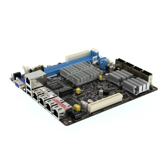
Page 21: Motherboard Layout
C-series FCBGA AST2300 DM_LAN1 processor FRNT_FAN2 _USB2_1 FRNT_FAN1 CPU_FAN1 Realtek RTL8211D LAN1 RT8166B CLRTC1 M.2(SOCKET3) LAN2 Marvell MSATA_SW1 88SE9485 Marvell 88E1543 LAN3 Quad PHY Super BUZZER LAN4 Marvell VR544200L VGA_SW1 BMC_SW1 88SE9485 PHY_SW1 3816565F 64Mb PCIE1 BIOS ASUS P9A-I Series... -
Page 22: Layout Contents
P9A-I/C2550/4L LAN34_LED1 AUX_PANEL1 SB_PWR1 EATXPWR1 PWR_SW1 PANEL1 DDR3_DIMM_B1 (64bit, 240-pin module) LED1 DDR3_DIMM_A1 (64bit, 240-pin module) P9A-I/C2550/4L SATAPWR1 SATA6G_1 COM1 BMC_LED1 SATA6G_2 CON1 Intel ® Atom C-series FCBGA AST2300 DM_LAN1 processor FRNT_FAN2 _USB2_1 FRNT_FAN1 CPU_FAN1 Realtek RTL8211D LAN1 RT8166B CLRTC1 M.2(SOCKET3) LAN2 MSATA_SW1... - Page 23 Serial port connector (10-1 pin COM1) 2-17 System panel connector (20-1 pin PANEL1) 2-19 LAN34_LED connector (5-1 pin LAN34_LED1) 2-22 SATA power connector (4-pin SATAPWR1) 2-18 Thermal sensor cable connector (3-pin TR1) 2-21 Auxiliary panel connector (20-2 pin AUX_PANEL1) 2-20 ASUS P9A-I Series...
-
Page 24: Central Processing Unit (Cpu)
Central Processing Unit (CPU) ® ® The motherboard comes with an integrated Intel Atom C-Series FCBGA processor. P9A-I Integrated Intel Atom ® C-series FCBGA processor P9A-I CPU System memory 2.4.1 Overview The motherboard comes with two Double Data Rate 3 (DDR3) Dual Inline Memory Modules (DIMM) sockets. -
Page 25: Installing A Dimm On A Single Clip Dimm Socket
Press the retaining clip outward to unlock the DIMM. Remove the DIMM from the socket. Support the DIMM lightly with your fingers when pressing the retaining clips. The DIMM might get damaged when it flips out with extra force. ASUS P9A-I Series... -
Page 26: Expansion Slots
Expansion slots In the future, you may need to install expansion cards. The following subsections describe the slots and the expansion cards that they support. Ensure to unplug the power cord before adding or removing expansion cards. Failure to do so may cause you physical injury and damage motherboard components. -
Page 27: Interrupt Assignments
The onboard PCIE x8 slot provides one x4 Gen2 link to CPU1. This slot supports various server class high performance add-on cards such as SCSI RAID card, fiber-channel card, and others. P9A-I No.(Slot location) Short Description PCIE1 1 x PCI-E x8 (x4 Gen2 link) 2-11 ASUS P9A-I Series... -
Page 28: Onboard Leds
The BMC LED works with the ASUS ASMB7 management device and indicates its initiation status. When the PSU is plugged and the system is OFF, ASUS ASMB7 management device starts system initiation for about one (1) minute. The BMC LED blinks after system initiation finishes. -
Page 29: Jumpers
SATA M.2 or SATA III devices are detected. Set to pins 2–3 to enable the SATA M.2 controller with SATA III interface disabled. MSATA_SW1 P9A-I Auto m2Sata (Default) P9A-I SATA M.2 and SATA III selection 2-13 ASUS P9A-I Series... - Page 30 VGA controller setting (3-pin VGA_SW1) This jumper allows you to enable or disable the onboard VGA controller. Set to pins 1– 2 to activate the VGA feature. P9A-I VGA_SW1 Enable Disable (Default) P9A-I VGA setting Baseboard Management Controller setting (3-pin BMC_SW1) This jumper allows you to enable or disable the ASMB7 remote server management feature.
-
Page 31: Connectors
Status Description Status Description No link 10 Mbps connection Green Linked Orange 100 Mbps connection Green Data activity Green 1 Gbps connection LAN port (Blinking) Green Ready to wake (Blinking then up from S5 steady) mode 2-15 ASUS P9A-I Series... -
Page 32: Internal Connectors
2.8.2 Internal connectors Serial ATA 6.0 Gb/s connectors (7-pin SATA 6G_1 connector [Light Blue]) (7-pin SATA 6G_2 connector [Gray], for SATA 6Gb/s or M.2 connector) These connectors are for the Serial ATA signal cables for Serial ATA hard disk drives that allows up to 6Gb/s of data transfer rate. - Page 33 DO NOT forget to connect the fan cables to the fan connectors. Insufficient air flow inside the system may damage the motherboard components. • These are not jumpers! DO NOT place jumper caps on the fan connectors! • All fans feature the ASUS Smart Fan technology. FRNT_FAN4 FRNT_FAN2 SENSE FRNT_FAN3...
- Page 34 ATX power connectors (24-pin EATXPWR1, 4-pin CON1) These connectors are for the ATX power supply plugs. The power supply plugs are designed to fit these connectors in only one orientation. Find the proper orientation and push down firmly until the connectors completely fit. •...
-
Page 35: System Panel Connector
This 3-pin connector is for the system power LED. Connect the chassis power LED cable to this connector. The system power LED lights up when you turn on the system power, and blinks when the system is in sleep mode. 2-19 ASUS P9A-I Series... - Page 36 Auxiliary panel connector (20-2 pin AUX_PANEL1) This connector is for additional front panel features including front panel SMB, locator LED and switch, chassis intrusion, and LAN LEDs. P9A-I P9A-I Auxiliary panel connector Front panel SMB (6-1 pin FPSMB) These LEDs connect the front panel SMBus cable. LAN activity LED (2-pin LAN1LINK and 2-pin LAN2LINK) These LEDs are for Gigabit LAN activity LEDs on the front panel.
- Page 37 Thermal sensor cable connector (3-pin TR1) These connectors are for temperature monitoring. Connect the thermal sensor cables to these connectors and place the other ends to the devices, which you want to monitor temperature. P9A-I P9A-I Thermal sensor cable connector 2-21 ASUS P9A-I Series...
- Page 38 LAN34_LED connector (5-1 pin LAN34_LED1) These LEDs are for Gigabit LAN activity LEDs on the front panel. Connect the LAN LED cable to the backplane for LAN activity indication. LAN34_LED1 PIN 1 P9A-I P9A-I LAN3 & LAN4 LED Chapter 2: Hardware information 2-22...
-
Page 39: Chapter 3: Powering Up
Chapter 3: Powering Up... -
Page 40: Chapter Summary
Chapter summary This chapter describes the power up sequence, and ways of shutting down the system.This chapter contains the following sections: Starting up for the first time ..............3-3 Powering off the computer ................ 3-4 ASUS P9A-I Series... -
Page 41: Starting Up For The First Time
30 seconds from the time you turned on the power, the system may have failed a power-on test. Check the jumper settings and connections or call your retailer for assistance. At power on, hold down the <Del> key to enter the BIOS Setup. Follow the instructions in Chapter 4. ASUS P9A-I Series... -
Page 42: Powering Off The Computer
Powering off the computer 3.2.1 Using the OS shut down function ® Using Windows Server 2008 R2: Click the Start button, move the cursor to the triangle on the right of Log off, then click Shut Down. From the Shutdown Event Tracker, select the option that best describes why you want to shut down the computer. -
Page 43: Chapter 4: Bios Setup
Chapter 4: BIOS setup... - Page 44 Advanced menu ..................4-11 IntelRCSetup menu .................. 4-28 Server Mgmt menu ................... 4-50 Event Logs menu ..................4-55 Security ..................... 4-57 Boot menu ....................4-60 4.10 Monitor menu ................... 4-61 4.11 Tool menu ....................4-62 4.12 Exit menu ....................4-62 ASUS P9A-I Series...
-
Page 45: Managing And Updating Your Bios
4.1.1 ASUS CrashFree BIOS 3 utility The ASUS CrashFree BIOS 3 is an auto recovery tool that allows you to restore the BIOS file when it fails or gets corrupted during the updating process. You can update a corrupted BIOS file using a USB flash drive that contains the updated BIOS file. -
Page 46: Asus Ezflash Utility
4.1.2 ASUS EzFlash Utility The ASUS EzFlash Utility feature allows you to update the BIOS using a USB flash disk without having to use a DOS-based utility. Download the latest BIOS from the ASUS website at www.asus.com before using this utility. -
Page 47: Bupdater Utility
Updating the BIOS file To update the BIOS file using the BUPDATER utility: Visit the ASUS website at www.asus.com and download the latest BIOS file for the motherboard. Save the BIOS file to a bootable USB flash disk drive. Download the BUPDATER utility (BUPDATER.exe) from the ASUS support website at support.asus.com to the bootable USB flash disk drive you created earlier. - Page 48 The utility verifies the file, then starts updating the BIOS file. ASUSTek BIOS Update for DOS V1.06 (09/08/04) FLASH TYPE: MXIC 25L1605A Current ROM Update ROM BOARD: P9A-I BOARD: P9A-I VER: 0201 VER: 0202 DATE: 04/10/2014 DATE: 04/15/2014 PATH: WARNING! Do not turn off power during flash BIOS Note Writing BIOS: DO NOT shut down or reset the system while updating the BIOS to prevent system boot...
-
Page 49: Bios Setup Program
The BIOS setup screens shown in this section are for reference purposes only, and may not exactly match what you see on your screen. • Visit the ASUS website (www.asus.com) to download the latest BIOS file for this motherboard. ASUS P9A-I Series... -
Page 50: Bios Menu Screen
4.2.1 BIOS menu screen Menu items Menu bar Configuration fields General help Aptio Setup Utility - Copyright (C) 2013 American Megatrends, Inc. Main Advanced IntelRCSetup Server Mgmt Event Logs Security Boot Monitor Tool Exit BIOS Information Choose the system default BIOS Vendor American Megatrends language... -
Page 51: Menu Items
A scroll bar appears on the right side of a menu screen when there are items that do not fit on the screen. Press the Up/Down arrow keys or <Page Up> /<Page Down> keys to display the other items on the screen. ASUS P9A-I Series... -
Page 52: Main Menu
Main menu When you enter the BIOS Setup program, the Main menu screen appears. The Main menu provides you an overview of the basic system information, and allows you to set the system date, time, and language settings. Aptio Setup Utility - Copyright (C) 2013 American Megatrends, Inc. Main Advanced IntelRCSetup Server Mgmt Event Logs Security Boot Monitor Tool Exit BIOS Information... -
Page 53: Advanced Menu
Intel(R) Ethernet Connection I354-40:16:7E:7F:D8:07 Intel(R) Ethernet Connection I354-40:16:7E:7F:D8:08 Intel(R) Ethernet Connection I354-40:16:7E:7F:D8:09 Intel(R) Ethernet Connection I354-40:16:7E:7F:D8:0A Driver Health 4.4.1 Enable CRID [Disabled] Allows you to enable or disable the compatible revision ID. Configuration options: [Enabled] [Disabled] ASUS P9A-I Series 4-11... -
Page 54: Acpi Settings
4.4.2 ACPI Settings Aptio Setup Utility - Copyright (C) 2013 American Megatrends, Inc. Advanced Enables or Disables BIOS ACPI Settings ACPI Auto Configuration. Enabled for Windows XP and Enable ACPI Auto Configuration [Disabled] Linux (OS optimized for Hyper-Threading Technology) Enable Hibernation [Disabled] and Disabled for other OS ACPI Sleep State... -
Page 55: Nct6779D Super Io Configuration
Device Mode [STD Printe...] Allows you to select the Printer Port mode. Configuration options: [STD Printer Mode] [SPP Mode] [EPP-1.9 and SPP Mode] [EPP-1.7 and SPP Mode] [ECP Mode] [ECP and EPP 1.9 Mode] [ECP and EPP 1.7 Mode] ASUS P9A-I Series 4-13... -
Page 56: Serial Port Console Redirection
4.4.4 Serial Port Console Redirection Aptio Setup Utility - Copyright (C) 2013 American Megatrends, Inc. Advanced Console Redirection COM1 Enable or Disable. Console Redirection [Disabled] Console Redirection Settings COM2 (Disabled) Console Redirection Port Is Disabled Serial Port for Out-of-Band Management/ Windows Emergency Management Services (EMS) Console Redirection [Disabled]... - Page 57 Long or noisy lines may require lower speeds. Configuration options: [9600] [19200] [57600] [115200] Flow Control [None] Allows you to set the flow control to prevent data loss from buffer overflow. Configuration options: [None] [Hardware RTS/CTS] [Software Xon/Xoff] ASUS P9A-I Series 4-15...
-
Page 58: Onboard Lan I354 Configuration
4.4.5 Onboard LAN I354 Configuration This allows you to change the enable or disable the onboard LAN. Aptio Setup Utility - Copyright (C) 2013 American Megatrends, Inc. Advanced Intel LAN Onboard LAN I354 Configuration Enable/Disable INTEL I354 LAN1 MAC: 40:16:7E:7F:D8:07 INTEL I354 LAN2 MAC: 40:16:7E:7F:D8:08 INTEL I354 LAN3 MAC:... -
Page 59: Apm
Power On By RTC [Disabled] This item allows you to enable or disable RTC to generate a wake event. When set to [Enabled], the items RTC Alarm Date (Days) and Hour/Minute/Second becomes user-configurable where you can set values. ASUS P9A-I Series 4-17... -
Page 60: Pci Subsystem Settings
4.4.7 PCI Subsystem Settings Allows you to configure PCI, PCI-X, and PCI Express Settings. Aptio Setup Utility - Copyright (C) 2013 American Megatrends, Inc. Advanced Value to be programmed PCI Bus Driver Version A5.01.06 into PCI Latency Timer Register. PCI Devices Common Settings PCI Latency Timer [32 PCI Bus Clocks] PCI-X Latency Timer... - Page 61 ASPM is a power management protocol that is used to extend battey life. Configuration options: [Disabled] Disables ASPM. [Auto] BIOS auto configuration. Extended Synch [Disabled] Enable this item to allow generation of extended synchronization patterns. Configuration options: [Disabled] [Enabled] ASUS P9A-I Series 4-19...
- Page 62 Link Training Retry [5] Selects or disables the number of retry attempts that the software will take to retrain the link if the previous training attempt was unsuccessful. Configuration Options: [Disabled] [2] [3] [5] Link Training Timeout (us) [1000] Defines number of Microseconds that the software will wait before polling Link Training bit in Link Status register.
- Page 63 If your PCIe device supports this function, set this item to [Disabled] to disable the hardware's ability to change link speed except speed rate reduction for the purpose of correcting unstable link operation. Configuration Options: [Disabled] [Enabled] ASUS P9A-I Series 4-21...
-
Page 64: Network Stack Configuration
4.4.8 Network Stack Configuration Aptio Setup Utility - Copyright (C) 2013 American Megatrends, Inc. Advanced Enable/Disable UEFI Network stack [Disabled] Network Stack Network Stack [Disabled] Enables or disables the network stack feature. Configuration options: [Disabled] [Enabled] The following items appear only when Network Stack is set to [Enabled]. Ipv4 PXE Support [Enabled] Enables or disables the Ipv4 PXE Boot Support. - Page 65 Allows you to select the type of video devices that you want to launch. Configuration options: [Do not launch] [UEFI] [Legacy] Other PCI devices [Legacy] Allows you to select the type of other PCI devices that you want to launch. Configuration options: [UEFI] [Legacy] ASUS P9A-I Series 4-23...
-
Page 66: Trusted Computing
4.4.10 Trusted Computing Aptio Setup Utility - Copyright (C) 2013 American Megatrends, Inc. Advanced Enables or Disables BIOS Configuration Security Device Support [Disabled] support for security device.O.S. will not show Security Device. TCG Current Status Information EFI protocol and INT1A NO Security Device Found interface will not be available. - Page 67 Configuration options: [Auto] [Floppy] [Forced FDD] [Hard Disk] [CD-ROM] AMI Virtual HDISK0 1.00 [Auto] This item allows your system to detect the devices according to their media formats. Configuration options: [Auto] [Floppy] [Forced FDD] [Hard Disk] [CD-ROM] ASUS P9A-I Series 4-25...
-
Page 68: Iscsi Configuration
4.4.12 iSCSI Configuration This allows you to configure the iSCSI Initiator settings. Aptio Setup Utility - Copyright (C) 2013 American Megatrends, Inc. Advanced iSCSI Initiator Name The worldwide unique name of iSCSI Initiator. Only Add an Attempt IQN format is accepted. Delete Attempts Change Attempt Order 4.4.13... -
Page 69: Driver Health
4.4.14 Driver Health Displays the status of the drivers and controllers. Aptio Setup Utility - Copyright (C) 2013 American Megatrends, Inc. Advanced Provides Health Status Intel(R) PRO/1000 5.8.09 PCI-E Healthy for the Drivers/ Controllers ASUS P9A-I Series 4-27... -
Page 70: Intelrcsetup Menu
IntelRCSetup menu The IntelRCSetup menu items allow you to change the processor and chipset settings. Aptio Setup Utility - Copyright (C) 2013 American Megatrends, Inc. Main Advanced IntelRCSetup Server Mgmt Event Logs Security Boot Monitor Tool Exit MRC Version 1.0.0.39 Relaxes the security Microcode Revision 00000121... -
Page 71: Processor Configuration
Allows you to enable or disable the Enhanced Intel SpeedStep Technology (EIST). Configuration options: [Auto] [Enable] [Disable] P-state Coordination [Package] Selects package or module level P-state Ratio Coordination. VID always resovlves to the highest P-state VID of any core in the SoC. Configuration options: [Package] [Module] [Hardware] ASUS P9A-I Series 4-29... - Page 72 TM1 [Enable] Enables or disables TM1. Configuration options: [Enable] [Disable] TM2 Mode [Adaptive Throttling] Selects LFM Throttling or Adaptive Throttling for TM2 mechanisms. Configuration options: [LFM Throttling] [Adaptive Throttling] CPU C State [Auto] Allows you to enable or disable the enhanced Cx state of the CPU. Configuration options: [Auto] [Enable] [Disable] Enhanced Halt State (C1E) [Disable] Allows you to enable or disable the enhanced C1E state of the CPU.
- Page 73 Allows you to choose the number of CPU cores to activate in SoC package. Configuration options: [All] [4] [2] CPU Flex Ratio Override [Disable] Enables or disables the CPU Flex Ratio Override programming. Configuration options: [Disable] [Enable] ASUS P9A-I Series 4-31...
-
Page 74: Thermal Configuration
4.5.2 Thermal Configuration Aptio Setup Utility - Copyright (C) 2013 American Megatrends, Inc. Main Advanced IntelRCSetup Server Mgmt Event Logs Security Boot Monitor Tool Exit Thermal Configuration Offset below TJMAX to set as the PROCHOT# TJ Target activation temperature. [Enable] Valid range 0C to 63C. - Page 75 Set this item to [Enable] to trigger an interrupt when the temperature goes from HOT to NOT_ HOT. Configuration options: [Enable] [Disable] High Temp Interrupt [Enable] Set this item to [Enable] to trigger an interrupt when the temperature goes from NOT_HOT to HOT. Configuration options: [Enable] [Disable] ASUS P9A-I Series 4-33...
- Page 76 Threshold 1 [5] Sets the temperature below TJMAX to signal an interrupt whenever the temperature crosses this threshold. The values range from 0˚C to 127˚C. Threshold 2 [10] Sets the temperature below TJMAX to signal an interrupt whenever the temperature crosses this threshold.
- Page 77 Offset B2h: PTPS [0] Sets the programmable Trip Point settings. RTF Throttle Period [37.5% clkon] Specifies the root fabric throttling period. Configuration options: [100% clkon] [87.5% clkon] [75.0% clkon] [62.5% clkon] [50.0% clkon] [37.5% clkon] [25.0% clkon] [12.5% clkon] ASUS P9A-I Series 4-35...
-
Page 78: Usb Configuration
Thermal Trip Events Allows you to set the thermal trip events. Aptio Setup Utility - Copyright (C) 2013 American Megatrends, Inc. Main Advanced IntelRCSetup Server Mgmt Event Logs Security Boot Monitor Tool Exit Thermal Trip Events [20]:SLM3 Prochot [19]:SLM2 Prochot Offset B5h: TTE_AUX0 [18]:SLM1 Prochot Offset B6h: TTE_AUX1... -
Page 79: Network Configuration
AB Segments in DRAM [Disabled] E Segment in DRAM [Enabled] F Segment in DRAM [Enabled] ZQ Calibration [Enabled] Rank Margin Tool [Disabled] RMT CPGC exp_loop_cnt [12] RMT CPGC num_bursts Version 2.16.1243. Copyright (C) 2013 American Megatrends, Inc. ASUS P9A-I Series 4-37... - Page 80 Navigate to the second page of the screen to see the rest of items in this menu by pressing the Up or Down arrow keys. To quickly go to the last item of the second page, press the Page Down button. Press the Page Up button to go back to the first item in the first page.
- Page 81 Allows Rank 1 to be tested. Configuration options: [Enabled] [Disabled] Rank 2 [Enabled] Allows Rank 2 to be tested. Configuration options: [Enabled] [Disabled] Rank 3 [Enabled] Allows Rank 3 to be tested. Configuration options: [Enabled] [Disabled] ASUS P9A-I Series 4-39...
- Page 82 Pass Gate MonteCarlo [Disabled] Set this item to [Enabled] to search in Algorithm to find PG Max. Configuration options: [Enabled] [Disabled] The following items become configurable only when you set Pass Gate MonteCarlo to [Enabled]. Pass Gate Max Failures [50] Sets the number of failures before going into the repetition value.
- Page 83 Propagate Errors to Cores (BMCMODE) [Disabled] Enables or disables the Bunit Machine Check Mode to propagate errors to cores. Configuration options: [Enabled] [Disabled] CMD Rate [Auto] Sets the CMD rate. Configuration options: [Auto] [1N] [2N] [3N] ASUS P9A-I Series 4-41...
- Page 84 Out of order memory processing [Enabled] Enable this item to improve system performance. Configuration options: [Enabled] [Disabled] Out of order aging threshold [31] Specifies the number of requests that can be processed ahead of another request sitting in the In-Progress request queue before 000 is disabled. New request bypass [Enabled] Enable this item to enable new memory requests to be processed immediately and skip the In-Progress request queue when the queue is empty.
- Page 85 Configuration options: [Auto] [4] ~ [7] tFAW [Auto] Configuration options: [Auto] [16] ~ [36] tCCD [Auto] Configuration options: [Auto] [4] [12] [18] tWTP [Auto] Configuration options: [Auto] [15] ~ [30] tWCL [Auto] Configuration options: [Auto] [5] ~ [9] ASUS P9A-I Series 4-43...
-
Page 86: Wake On Lan Configuration
4.5.7 Wake On Lan Configuration Aptio Setup Utility - Copyright (C) 2013 American Megatrends, Inc. Main Advanced IntelRCSetup Server Mgmt Event Logs Security Boot Monitor Tool Exit Wake On Lan Configuration Wake On Lan Configuration settings Wake On Lan Configuration [Enable] Wake On Lan Configuration [Enable] Enables or disables the Wake On LAN feature. -
Page 87: Sata Configuration
Selects whether or not to allow to overwrite SIR values. Configuration options: [Disabled] [Enabled] SATA Port 1 Sata port 1 [Enabled] Enables or disables the SATA device connected to SATA port 1. Configuration options: [Enabled] [Disabled] ASUS P9A-I Series 4-45... - Page 88 Spin up [Disabled] Enables or disables the Spin-Up device. Configuration options: [Enabled] [Disabled] Hot plug [Enabled] Allows you to enable or disable SATA Hot Plug support. Configuration options: [Disabled] [Enabled] External device [Disabled] Enables or disables other external devices. Configuration options: [Enabled] [Disabled] Mechanical Switch [Disabled] Enables or disables the mechanical switch.
-
Page 89: Ppm Config
Main Advanced IntelRCSetup Server Mgmt Event Logs Security Boot Monitor Tool Exit Enable/Disable C-state C-state POPUP [Enabled] POPUP C-state POPUP [Enabled] Enable this item to allow the system to transit from C3/C4 State to C2 State. Configuration options: [Enabled] [Disabled] ASUS P9A-I Series 4-47... -
Page 90: System Event Log
4.5.9 System Event Log Aptio Setup Utility - Copyright (C) 2013 American Megatrends, Inc. Main Advanced IntelRCSetup Server Mgmt Event Logs Security Boot Monitor Tool Exit System Event Log System Error Enable/ Disable Auto setup System Errors [Enable] options. If Auto is Memory Event Log selected the enabling or PCIe Event Log... - Page 91 Enable this item to set error type with address and vendor extensions. Configuration options: [Enable] [Disable] Whea Logging [Enable] Enables or disables WHEA logging of errors. Configuration options: [Enable] [Disable] Native AER [Enable] Enables or disables Native Advanced Error reporting. Configuration options: [Enable] [Disable] ASUS P9A-I Series 4-49...
-
Page 92: Server Mgmt Menu
Server Mgmt menu The Server Mgmt menu displays the server management status, and allows you to change the settings. Aptio Setup Utility - Copyright (C) 2013 American Megatrends, Inc. Main Advanced IntelRCSetup Server Mgmt Event Logs Security Boot Monitor Tool Exit BMC Self Test Status PASSED If enabled, starts a BIOS... -
Page 93: System Event Log
Allows you to choose options for reactions to a full SEL. Configuration options: [Do Nothing] [Erase Immediately] Log EFI Status Codes [Error code] Sets the logging of EFI status codes. Configuration options: [Disabled] [Both] [Error code] [Progress code] ASUS P9A-I Series 4-51... -
Page 94: View Fru Information
4.6.2 View FRU information This menu displays the FRU information. Aptio Setup Utility - Copyright (C) 2013 American Megatrends, Inc. Main Advanced IntelRCSetup Server Mgmt Event Logs Security Boot Monitor Tool Exit FRU information System Manufacturer Intel System Product Name EPGSVR System Version System Serial Number... -
Page 95: View System Event Log
IPv6 BMC Lan IP Address source [Previous State] Select to configure LAN channel parameters statically or dynamically (by BIOS or BMC). Unspecified option will not modify any BMC network parameters during BIOS phase. Configuration options: [Previous State] [Static] [Dynamic-Obtained by BMC running DHCP] ASUS P9A-I Series 4-53... - Page 96 The following items appear only when you set IPv6 BMC Lan IP Address source to [Static]. IPv6 BMC Lan IP Address Allows you to key in IPv6 BMC Lan IP address. IPv6 BMC Lan IP Prefix Length Allows you to key in IPv6 BMC Lan IP prefix length. IPv6 BMC Lan Default Gateway Allows you to key in default Gateway IP address for IPv6 BMC Lan.
-
Page 97: Event Logs Menu
Enables or disables logging of system boot event. Configuration options: [Disabled] [Enabled] MECI [1] Sets the Multiple Event Count Increment (MECI). The values range from 1 to 255. METW [60] Sets the Multiple Event Time Window (METW). The values range from 0 to 99. ASUS P9A-I Series 4-55... -
Page 98: View Smbios Event Log
Log OEM Codes [Enabled] Enables or disables logging of EFI status codes as OEM codes (if not already converted to legacy). Configuration options: [Disabled] [Enabled] Convert OEM Codes [Disabled] Enables or disables converting EFI status codes to Standard Smbios types (Not all may be translated). -
Page 99: Security
From the Create New Administrator Password box, key in a new password, then press <Enter>. Confirm the password when prompted. To clear the administrator password, follow the same steps as in changing an administrator password, but press <Enter> when prompted to create/confirm the password. ASUS P9A-I Series 4-57... -
Page 100: User Password
User Password To set a user password: Select the User Password item and press <Enter>. From the Create New User Password box, key in a password, then press <Enter>. Confirm the password when prompted. To change a user password: Select the User Password item and press <Enter>. From the Enter Current User Password box, key in the current password, then press <Enter>. - Page 101 This item will ask you if you want to save all secure boot variables. Select Yes if you want to save all secure boot variables, otherwise select No. Platform Key (PK)/ Key Exchange Key (KEK)/ Authorized Signatures (DB)/ Authorized TimeStamps (DBT)/ Forbidden Signatures (DBX) Configuration options: [Set New] [Delete] [Append] ASUS P9A-I Series 4-59...
-
Page 102: Boot Menu
These items specify the boot device priority sequence from the available devices. The number of device items that appears on the screen depends on the number of devices installed in the system. • To select the boot device during system startup, press <F8> when ASUS Logo appears. ® •... -
Page 103: Monitor Menu
Fan Speed Control [Generic Mode] Allows you to configure the ASUS Smart Fan feature that smartly adjusts the fan speeds for more efficient system operation. Configuration options: [Low Speed Mode] [Generic Mode] [High Speed Mode] [Full Speed Mode] [Manual Speed Mode] The following items appear only when you set Fan Speed Control to [Manual Speed Mode]. -
Page 104: Tool Menu
Start EzFlash utility to select and update BIOS. Start EzFlash utility Allows you to run the Start EzFlash utility. For more information, see section 4.1.2 ASUS EzFlash Utility. 4.12 Exit menu The Exit menu items allow you to save or discard your changes to the BIOS items. -
Page 105: Save Changes
Launch EFI Shell from filesystem device This option allows you to launch the EFI Shell application (shellx64.efi) from one of the available filesystem devices. Select Yes to proceed, or No to cancel, and then press <Enter>. ASUS P9A-I Series 4-63... - Page 106 Chapter 4: BIOS setup 4-64...
-
Page 107: Chapter 5: Driver Installation
Chapter 5: Driver installation... - Page 108 This chapter contains the following sections: Management applications and utilities installation ........ 5-3 Running the Support DVD ................ 5-3 Installing the LAN driver ................5-11 Installing the VGA driver ................. 5-16 ® Installing the Intel I354 Gigabit Adapters driver ........5-19 ASUS P9A-I Series...
-
Page 109: Management Applications And Utilities Installation
• The contents of the support DVD are subject to change at any time without notice. Visit the ASUS website (www.asus.com) for the latest updates on software and utilities. • The support DVD is supported on Windows... - Page 110 5.2.1 Drivers menu tab The Drivers Menu shows the available device drivers if the system detects installed devices. Install the necessary drivers to activate the devices. 5.2.2 Utilities menu tab The Utilities menu displays the software applications and utilities that the motherboard supports.
-
Page 111: Manual Menu
The Make Disk menu contains items to create the Marvell 9485 SAS/SATA2 controller driver disks. 5.2.4 Manual menu The Manual menu contains the motherboard user guide. The user guide is in Portable Document Format (PDF). Install the Adobe Reader from the ® Utilities menu before opening it. ASUS P9A-I Series... - Page 112 5.2.5 Contact information menu The Contact menu displays the ASUS contact information, e-mail addresses, and useful links if you need more information or technical support for your motherboard. 5.2.6 Installing the Intel chipset device software driver ® ® This section provides the instructions on how to install the Intel chipset device software on the system.
- Page 113 ® From the Intel Chipset Device Software, click Next to start the installation. In the License Agreement window, click Yes to continue. Read the Readme File information and click Next to continue. ASUS P9A-I Series...
- Page 114 Click Install in the Windows Security window. The Windows Security window may appear more than once and you may have to click Install several times to continue with the installation. When finished, click Next. When prompted to restart the computer, select Yes, I want to restart this computer now then click Finish to complete the installation.
- Page 115 DVD. ® Click Intel Chipset Device Software from the Drivers menu to start the installation. ® From the Intel Chipset Device Software, click Next. In the License Agreement window, click Yes to continue the process. ASUS P9A-I Series...
- Page 116 Read the Readme File information and click Next to continue. When finished, click Next. When prompted to restart the computer, select Yes, I want to restart this computer now then click Finish to complete the installation. 5-10 Chapter 5: Driver installation...
-
Page 117: Installing The Lan Driver
ASSETUP.EXE from the Bin folder. Double-click the ASSETUP.EXE to run the support DVD. ® Click Intel Network Connections Software on the Drivers tab to start the installation. ® From the Intel Network Connections window, click Install Drivers and Software. ASUS P9A-I Series 5-11... - Page 118 Click Next in the Welcome to the install wizard for Intel(R) Network Connections. From the License Agreement window, select I accept the terms in the license agreement then click Next. Select the drivers you want to install in the Setup Options window and click Next. From the Ready to Install the Program window, click Install.
- Page 119 If Autorun is NOT enabled in your computer, browse the contents of the support DVD to locate the file ASSETUP.EXE from the Bin folder. Double-click the ASSETUP.EXE to run the support DVD. Click Intel Network Connections Software on the Drivers menu to start the installation. ® ASUS P9A-I Series 5-13...
- Page 120 From the Intel Network Connections ® window, click Install Drivers and Software. Click Next in the Welcome to the install wizard for Intel(R) Network Connections window. From the License Agreement window, select I accept the terms in the license agreement then click Next. Select the drivers you want to install in the Setup Options window and click Next.
- Page 121 Click Install to continue. When done, click Finish to complete the installation. ASUS P9A-I Series 5-15...
-
Page 122: Installing The Vga Driver
Installing the VGA driver This section provides the instructions on how to install the ASPEED Video Graphics Adapter (VGA) driver. To install the ASPEED VGA driver on Windows Server 2008 R2: ® Restart the computer. Log in with Administrator privileges. Insert the Motherboard Support DVD to the optical drive. - Page 123 Click Install to begin the installation. When done, click Finish. When prompted to restart the computer, click Yes. ASUS P9A-I Series 5-17...
- Page 124 To install the ASPEED VGA driver on Windows Server 2012: ® Restart the computer. Log in with Administrator privileges. Insert the Motherboard Support DVD to the optical drive. The support DVD automatically displays the Drivers menu if Autorun is enabled in your computer.
-
Page 125: Installing The Intel ® I354 Gigabit Adapters Driver
ASSETUP.EXE from the Bin folder. Double-click the ASSETUP.EXE to run the support DVD. Click Intel I354 Gigabit Adapters Driver in the Drivers tab of the main screen to start the installation. Click Next to continue. From the Program Maintenance window, select Modify then click Next. ASUS P9A-I Series 5-19... - Page 126 Select the options you want to install then click Next to continue. Click Install in the Ready to Modify the Program window to begin with the loading of the selected options. When done, click Finish. 5-20 Chapter 5: Driver installation...
- Page 127 Click Intel I354 Gigabit Adapters Driver in the Drivers tab of the main screen to start the installation. Click Next to continue. From the Program Maintenance window, select Modify then click Next. Select the options you want to install then click Next to continue. ASUS P9A-I Series 5-21...
- Page 128 In the Ready to Modify the Program window, click Install to load the options you selected. When done, click Finish. 5-22 Chapter 5: Driver installation...
-
Page 129: Appendix A: Reference Information
Appendix A: Reference Information... -
Page 130: A.1 Block Diagram
Chapter summary This appendix includes additional information that you may refer to when configuring the motherboard. This chapter contains the following sections: Block diagram ................... A-3 ASUS P9A-I Series... -
Page 131: Block Diagram
Storage C2750, C2550 Rear USB2.0 4x1 Gbe LANs LPC BUS port x 2 25MHz SATA0 NCT 6779D SATA 6G/s BUS SATA1 Switch COM1/Hardware Monitor M2 Type SATA RGMII Realtek AST2300 RTL8211D (128Mbytes DDR3 SDRAM) RJ45 BMC LAN ASUS P9A-I Series... - Page 132 P9A-I/C2550/4L VRD 12.0 on board 2 DDR3 1600 UDIMM PCIEx4 Intel Atom ® PCIE1 X8 Slot(x4 link) SPI Flash & SPI TPM C -Series SGMIIx4 FCBGA Marvell Processor 88E1543 Rear USB2.0 Quad PHY (Avoton) port x 2 SATA0 C2550 4x1 Gbe LANs SATA 6G/s BUS LPC BUS SATA1...
-
Page 133: Asus Contact Information
ASUS contact information ASUSTeK COMPUTER INC. Address 15 Li-Te Road, Peitou, Taipei, Taiwan 11259 Telephone +886-2-2894-3447 +886-2-2890-7798 E-mail info@asus.com.tw Web site http://www.asus.com.tw Technical Support Telephone +86-21-38429911 +86-21-58668722 ext: 9101 Online Support http://support.asus.com/techserv/techserv.aspx ASUSTeK COMPUTER INC. (Taiwan) Address 15 Li-Te Road, Peitou, Taipei, Taiwan 11259... - Page 134 +1-510-608-4555 Web site http://usa.asus.com Technical Support Support fax +1-812-284-0883 General support +1-812-282-2787 Online support http://support.asus.com/techserv/techserv.aspx ASUS COMPUTER GmbH (Germany and Austria) Address Harkort Str. 21-23, D-40880 Ratingen, Germany +49-2102-959911 Web site http://www.asus.de Online contact http://www.asus.de/sales Technical Support Telephone +49-1805-010923 Support Fax +49-2102-959911 Online support http://support.asus.com/techserv/techserv.aspx...
- Page 135 Web site http://www.asus.com Technical Support Telephone +31-(0)591-5-70292 +31-(0)591-666853 E-mail advance.rma.eu@asus.com Online Support http://support.asus.com/techserv/techserv.aspx ASUS Polska Sp. z o.o. (Poland) Address Ul. Post pu 6, 02-676 Warszawa, Poland Web site http://pl.asus.com Technical Support Telephone +48-225718033 Online Support http://support.asus.com/techserv/techserv.aspx ASK-Service (Russia and CIS) Address г.Москва, ул.
Need help?
Do you have a question about the P9A-I Series and is the answer not in the manual?
Questions and answers