Sign In
Upload
Download
Table of Contents
Contents
Add to my manuals
Delete from my manuals
Share
URL of this page:
HTML Link:
Bookmark this page
Add
Manual will be automatically added to "My Manuals"
Print this page
×
Bookmark added
×
Added to my manuals
Manuals
Brands
Asus Manuals
Motherboard
P9D-M Series
Manual
Asus P9D-M Series Manual
Hide thumbs
Also See for P9D-M Series
:
User manual
(156 pages)
1
2
Table Of Contents
3
4
5
6
7
8
9
10
11
12
13
14
15
16
17
18
19
20
21
22
23
24
25
26
27
28
29
30
31
32
33
34
page
of
34
Go
/
34
Contents
Table of Contents
Bookmarks
Table of Contents
Table of Contents
Notices
Safety Information
About this Guide
Chapter 1: Product Introduction
Welcome
Package Contents
Serial Number Label
Special Features
Product Highlights
Innovative ASUS Features
Chapter 2: Hardware Information
Before You Proceed
Motherboard Overview
Placement Direction
Screw Holes
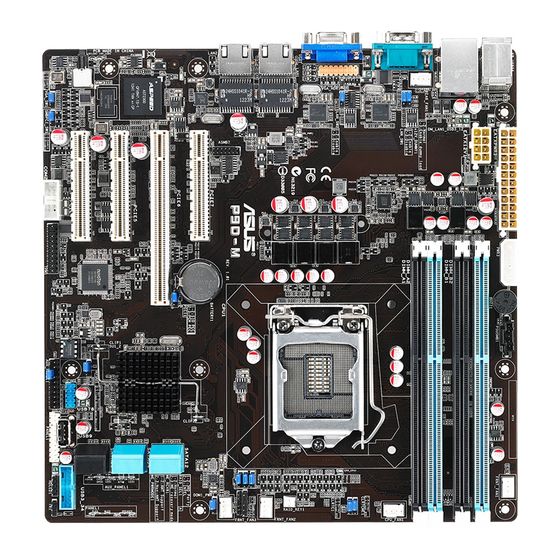
Motherboard Layout
Layout Contents
Central Processing Unit (CPU)
Installing the CPU
Advertisement
Quick Links
Download this manual
P9D-M Series
Table of
Contents
Previous
Page
Next
Page
1
2
3
4
5
Advertisement
Table of Contents
Need help?
Do you have a question about the P9D-M Series and is the answer not in the manual?
Ask a question
Questions and answers
Related Manuals for Asus P9D-M Series
Motherboard ASUS P9D-M Series User Manual
P9d-m series (156 pages)
Motherboard Asus P9D-I Manual
P9d-i manual (182 pages)
Motherboard Asus P9D WS User Manual
(154 pages)
Motherboard ASUS P9D-E/4L User Manual
(159 pages)
Motherboard Asus P9D-V User Manual
Asus p9d-v motherboard user manual (150 pages)
Motherboard Asus P9D-MV Manual
(34 pages)
Motherboard Asus P9D-X Manual
(152 pages)
Motherboard Asus P9D-C Series Manual
(160 pages)
Motherboard Asus P9X79 Manual De Démarrage Rapide
(14 pages)
Motherboard Asus P9X79 User Manual
(156 pages)
Motherboard Asus P9X79 LE User Manual
(176 pages)
Motherboard Asus P9X79 WS Guía De Inicio Rápido
(14 pages)
Motherboard Asus P9X79 WS User Manual
Intel x79 express chipset (186 pages)
Motherboard Asus P9X79 DELUXE User Manual
(176 pages)
Motherboard Asus P9X79 PRO User Manual
Intel x79 express chipset (168 pages)
Motherboard ASUS P9A-I Series User Manual
(136 pages)
This manual is also suitable for:
P9d-m
P9d-mv
P9d-mx
Table of Contents
Print
Rename the bookmark
Delete bookmark?
Delete from my manuals?
Login
Sign In
OR
Sign in with Facebook
Sign in with Google
Upload manual
Upload from disk
Upload from URL


Need help?
Do you have a question about the P9D-M Series and is the answer not in the manual?
Questions and answers