Table of Contents
Advertisement
Advertisement
Table of Contents

Related Manuals for Asus P9X79 PRO


Summary of Contents for Asus P9X79 PRO
- Page 1 P9X79...
- Page 2 Product warranty or service will not be extended if: (1) the product is repaired, modified or altered, unless such repair, modification of alteration is authorized in writing by ASUS; or (2) the serial number of the product is defaced or missing.
-
Page 3: Table Of Contents
Product highlights................ 1-2 1.3.2 Dual Intelligent Processors 3 with New DIGI+ Power Control ..1-3 1.3.3 ASUS Exclusive Features ............1-4 1.3.4 ASUS Quiet Thermal Solution ............. 1-5 1.3.5 ASUS EZ DIY ................1-6 1.3.6 Other special features ..............1-7 Chapter 2: Hardware information Before you proceed ................... -
Page 4: Contents
3.5.6 APM ..................3-35 Monitor menu ................... 3-36 Boot menu ....................3-39 Tools menu ....................3-40 3.8.1 ASUS EZ Flash 2 Utility ............3-40 3.8.2 ASUS DRAM SPD Information ..........3-41 3.8.3 ASUS O.C. Profile ..............3-42 3.8.4 ASUS Drive Xpert ..............3-43 Exit menu .................... - Page 5 Sensor Recorder ............... 4-12 4.3.7 Probe II..................4-13 4.3.8 BT GO! ..................4-14 4.3.9 USB 3.0 Boost................4-15 4.3.10 ASUS SSD Caching ..............4-16 4.3.11 ASUS Update ................4-17 4.3.11 MyLogo2 ................... 4-18 4.3.12 Audio configurations..............4-20 RAID configurations ................4-21 4.4.1...
-
Page 6: Notices
Complying with the REACH (Registration, Evaluation, Authorisation, and Restriction of Chemicals) regulatory framework, we published the chemical substances in our products at ASUS REACH website at http://csr.asus.com/english/REACH.htm. DO NOT throw the motherboard in municipal waste. This product has been designed to enable proper reuse of parts and recycling. -
Page 7: Safety Information
Safety information Electrical safety • To prevent electrical shock hazard, disconnect the power cable from the electrical outlet before relocating the system. • When adding or removing devices to or from the system, ensure that the power cables for the devices are unplugged before the signal cables are connected. If possible, disconnect all power cables from the existing system before you add a device. -
Page 8: About This Guide
Where to find more information Refer to the following sources for additional information and for product and software updates. ASUS websites The ASUS website provides updated information on ASUS hardware and software products. Refer to the ASUS contact information. Optional documentation Your product package may include optional documentation, such as warranty flyers, that may have been added by your dealer. -
Page 9: Conventions Used In This Guide
Conventions used in this guide To ensure that you perform certain tasks properly, take note of the following symbols used throughout this manual. DANGER/WARNING: Information to prevent injury to yourself when trying to complete a task. CAUTION: Information to prevent damage to the components when trying to complete a task. -
Page 10: P9X79 Pro Specifications Summary
® * Hyper DIMM support is subject to the physical characteristics of individual CPUs. ** Refer to www.asus.com for the Memory QVL (Qualified Vendors Lists). Expansion slots 3 x PCI Express 3.0 x16 slots (Dual at x16/ x16 mode; Triple at... - Page 11 - Folder Sync, BT Transfer, Shot & Send, BT to Net, Music Player, Personal Manager, BT Turbo Remote ASUS Exclusive Features: - ASUS UEFI BIOS EZ Mode featuring friendly graphics user interface - ASUS SSD Caching - USB 3.0 Boost - Front Panel USB 3.0 Support...
- Page 12 BIOS features 64 Mb Flash ROM, UEFI BIOS, PnP, DMI 2.0, WfM 2.0, SM BIOS 2.6, ACPI 2.0a, Multi-language BIOS, ASUS EZ Flash 2, ASUS CrashFree BIOS 3 Manageability WfM 2.0, DMI 2.0, WOL by PME, WOR by PME, PXE...
-
Page 13: Chapter 1: Product Introduction
® The motherboard delivers a host of new features and latest technologies, making it another standout in the long line of ASUS quality motherboards! Before you start installing the motherboard, and hardware devices on it, check the items in your package with the list below. -
Page 14: Special Features
MHz frequency as default. Complete USB 3.0 Integration ASUS facilitates strategic USB 3.0 accessibility for both the front and rear panel – 6 USB 3.0 ports in total. Experience the latest plug & play connectivity at speeds up to 10 times faster than USB 2.0. -
Page 15: Dual Intelligent Processors 3 With New Digi+ Power Control
2-phase power dedicated to integrated memory controller. ASUS SSD Caching SSD caching from ASUS is easier than ever. At 3X faster, this feature boosts system performance by using an installed SSD with no capacity limitations as a cache for frequently accessed data. -
Page 16: Asus Exclusive Features
Unleash your performance with ASUS’ simple onboard switch or AI Suite II utility. The TPU chip offers precise voltage control and advanced monitoring through Auto Tuning and TurboV functions. Auto tuning offers a user friendly way to automatically optimize the system for fast, yet stable clock speeds, while TurboV enables unlimited freedom to adjust CPU frequencies and ratios for optimized performance in diverse situations. -
Page 17: Asus Quiet Thermal Solution
Combining usability and aesthetics, the stylish ASUS heatsink gives users an extremely silent and cool experience with elegant design. -
Page 18: Asus Ez Diy
ASUS EZ-Flash 2 ASUS EZ Flash 2 is a user-friendly utility that allows you to update the BIOS without using a bootable floppy disk or an OS-based utility. Chapter 1: Product Introduction... -
Page 19: Other Special Features
The motherboard is European Union’s Energy-related Products (ErP) ready, and ErP requires products to meet certain energy efficiency requirement in regards to energy consumptions. This is in line with ASUS vision of creating environment-friendly and energy-efficient products through product design and innovation to reduce carbon footprint of the product and thus mitigate environmental impacts. - Page 20 Chapter 1: Product Introduction...
-
Page 21: Chapter 2: Hardware Information
Before you install or remove any component, ensure that the ATX power supply is switched off or the power cord is detached from the power supply. Failure to do so may cause severe damage to the motherboard, peripherals, or components. ASUS P9X79 PRO... -
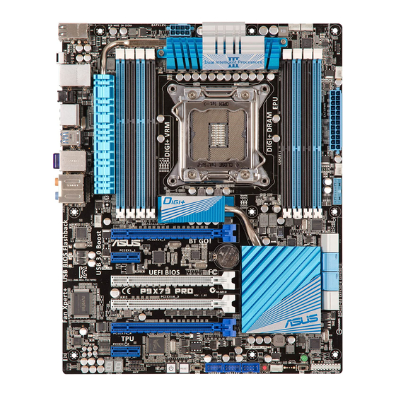
Page 22: Motherboard Overview
Motherboard overview 2.2.1 Motherboard layout Refer to 2.2.7 Internal connectors and 2.3.10 Rear panel connection for more information about rear panel connectors and internal connectors. Chapter 2: Hardware information... -
Page 23: Layout Contents
USB 2.0 connectors (10-1 pin USB910, USB1112, 2-28 USB1314) EPU switch 2-18 Reset switch 2-15 Power-on switch 2-15 Front panel audio connector (10-1 pin AAFP) 2-32 Digital audio connector (4-1 pin SPDIF_OUT) 2-29 Q-Code LED (LED1, LED2) 2-29 ASUS P9X79 PRO... -
Page 24: Central Processing Unit (Cpu)
Contact your retailer immediately if the PnP cap is missing, or if you see any damage to the PnP cap/socket contacts/motherboard components. ASUS will shoulder the cost of repair only if the damage is shipment/ transit-related. -
Page 25: System Memory
The motherboard comes with eight Double Data Rate 3 (DDR3) Dual Inline Memory Modules (DIMM) slots. A DDR3 module is notched differently from a DDR or DDR2 module. DO NOT install a DDR or DDR2 memory module to the DDR3 slot. Recommended memory configurations ASUS P9X79 PRO... -
Page 26: Memory Configurations
Memory configurations You may install 1GB, 2GB, 4GB and 8GB unbuffered ECC and non-ECC DDR3 DIMMs into the DIMM sockets. • You may install varying memory sizes in Channel A, Channel B, Channel C and Channel D. The system maps the total size of the lower-sized channel for the dual- channel configuration. - Page 27 4GB ( 2x DS - 9-9-9-24 1.65 • • 2GB ) KINGSTON KHX2133C9AD3T1FK4/8GX(XMP) 8GB ( 4x DS - 1.65 • • 2GB ) Patriot PVV34G2133C9K(XMP) 4GB ( 2x DS - 9-11-9-27 1.66 • • • 2GB ) ASUS P9X79 PRO...
- Page 28 P9X79 PRO Motherboard Qualified Vendors Lists (QVL) DDR3 2000 MHz capability Vendors Part No. Size Chip Brand Chip NO. Timing Voltage DIMM socket support (Optional) 2 DIMM 4 DIMM 6 DIMM 8 DIMM A-DATA AX3U2000GB2G9B(XMP) 9-11-9-27 1.55~1.75 • • • A-DATA AX3U2000GC4G9B(XMP) 9-11-9-27 1.55~1.75 •...
- Page 29 • G.SKILL F3-12800CL9D-8GBSR2(XMP) 8GB ( 2x 4GB ) 9-9-9-24 1.25 • • • • G.SKILL F3-12800CL8D-8GBECO(XMP) 8GB ( 2x4GB ) 8-8-8-24 1.35 • • GEIL GET316GB1600C9QC(XMP) 16GB ( 4x 4GB ) DS 9-9-9-28 1.6 • • • ASUS P9X79 PRO...
- Page 30 P9X79 PRO Motherboard Qualified Vendors Lists (QVL) DDR3 1600 MHz capability (continued) Vendors Part No. Size Chip Chip NO. Timing Voltage DIMM socket support (Optional) Brand 2 DIMM 4 DIMM 6 DIMM 8 DIMM KINGMAX FLGD45F-B8MF7(XMP) • • KINGSTON KHX1600C9D3K3/12GX(XMP) 12GB ( 3x 4GB ) DS 1.65 •...
- Page 31 KINGMAX FLFF65F-C8KM9 DS Kingmax KFC8FNMXF- • • • BXX-15A KINGSTON KVR1333D3N9/1G SS Elpida J1108BDSE-DJ-F • • • • KINGSTON KVR1333D3S8N9/2G SS Micron IFD77 D9LGK • • • • KINGSTON KVR1333D3N9/2G DS Kingston D1288JPNDPLD9U • • • ASUS P9X79 PRO 2-11...
- Page 32 P9X79 PRO Motherboard Qualified Vendors Lists (QVL) DDR3 1333 MHz capability (continued) Vendors Part No. Size Chip Brand Chip NO. Timing Voltage DIMM socket support (Optional) 2 DIMM 4 DIMM 6 DIMM 8 DIMM KINGSTON KHX1333C9D3UK2/4GX 4GB (2x 1.25 • •...
- Page 33 • Hyper DIMM support is subject to the physical characteristics of individual CPUs. Load the X.M.P. or D.O.C.P. settings in the BIOS for the hyper DIMM support. • Visit the ASUS website for the latest QVL. ASUS P9X79 PRO 2-13...
-
Page 34: Expansion Slots
2.2.4 Expansion slots Ensure to unplug the power cord before adding or removing expansion cards. Failure to do so may cause you physical injury and damage motherboard components. Slot No. Slot Description PCIe 3.0 x16_1 slot (single at x16) PCIe 2.0 x1_1 slot PCIe 3.0 x16_2 slot (triple at x16 / x8 / x8 mode) PCIe 3.0 x16_3 slot (at x8 mode) PCIe 3.0 x16_4 slot (dual at x16 / x16 mode) -
Page 35: Irq Assignments For This Motherboard
– – – – – PCIE x16_3 shared – – – – – – – PCIE x16_4 shared – – – – – – – PCIE x 1_2 shared – – – – – – – ASUS P9X79 PRO 2-15... -
Page 36: Onboard Switches
2.2.5 Onboard switches Onboard switches allow you to fine-tune performance when working on a bare or open- case system. This is ideal for overclockers and gamers who continually change settings to enhance system performance. Power-on switch The motherboard comes with a power-on switch that allows you to power up or wake up the system. - Page 37 BIOS default settings. A messgae will appear during POST reminding you that the BIOS has been restored to its default settings. • We recommend that you download and update to the latest BIOS version from the ASUS website at www.asus.com after using the MemOK! function. ASUS P9X79 PRO 2-17...
- Page 38 Clear RTC RAM switch Clear RTC RAM switch switch To erase the RTC RAM: Press down the CLR_CMOS switch. Hold down the <Del> key during the boot process and enter BIOS setup to re- enter data. TPU switch Turning this switch to Enable will automatically optimize the system for fast, yet stable clock speeds.
- Page 39 • You may change the EPU settings in the software application or BIOS setup program, and enable the EPU function at the same time. However, the system will use the last setting you have made. ASUS P9X79 PRO 2-19...
-
Page 40: Onboard Leds
2.2.6 Onboard LEDs Standby Power LEDs The Standby Power LEDs will light up once the system is connected to a power source. Q-LEDs The ID LEDs provide an elegant embellishment to the motherboard design. DRAM_LED CPU_LED VGA_LED P9X79 PRO BOOT_DEVICE_LED P9X79 PRO CPU/ DRAM/ BOOT_DEVICE/ VGA LED 2-20... - Page 41 • You may change the EPU settings in the software application or BIOS setup program, and enable the EPU function at the same time. However, the system will use the last setting you have made. ASUS P9X79 PRO 2-21...
- Page 42 Q-Code LEDs The Q-Code LED design provides you the 2-digit display, allowing you to know the system status. Refer to the Q-Code table below for details. Q-Code table Code Description Not used Power on. Reset type detection (soft/hard). AP initialization before microcode loading System Agent initialization before microcode loading PCH initialization before microcode loading Microcode loading...
- Page 43 Reserved for future AMI progress codes Recovery PPI is not available Recovery capsule is not found Invalid recovery capsule FB – FF Reserved for future AMI error codes DXE Core is started NVRAM initialization Installation of the PCH Runtime Services ASUS P9X79 PRO 2-23...
- Page 44 Q-Code table (continued) Code Description 63 – 67 CPU DXE initialization is started PCI host bridge initialization System Agent DXE initialization is started System Agent DXE SMM initialization is started 6B – 6F System Agent DXE initialization (System Agent module specific) PCH DXE initialization is started PCH DXE SMM initialization is started PCH devices initialization...
- Page 45 0x40 System is waking up from the S4 sleep state 0xAC System has transitioned into ACPI mode. Interrupt controller is in PIC mode. 0xAA System has transitioned into ACPI mode. Interrupt controller is in APIC mode. ASUS P9X79 PRO 2-25...
-
Page 46: Internal Connectors
2.2.7 Internal connectors ® Intel X79 Serial ATA 6.0 Gb/s connectors (7-pin SATA6G_1/2 [gray]) These connectors connect to Serial ATA 6.0 Gb/s hard disk drives via Serial ATA 6.0 Gb/s signal cables. If you installed Serial ATA hard disk drives, you can create a RAID 0, 1, 5, and 10 ®... - Page 47 Drive (the ODD should be connected to the Intel SATA ports), or else the ODD will not run. We strongly recommend you save the IRST Driver from SCD to the USB Flash Drive before OS installation. ASUS P9X79 PRO 2-27...
- Page 48 Marvell Serial ATA 6.0 Gb/s connectors (7-pin SATA6G_E1/E2 [grey]) ® These connectors connect to Serial ATA 6.0 Gb/s hard disk drives via Serial ATA 6.0 Gb/s signal cables. • The SATA6G_E1/E2 (grey) connectors are for data drives only. ATAPI device is not supported.
- Page 49 USB 3.0 connector, you can have a front panel USB 3.0 solution. You can connect the ASUS front panel USB 3.0 box to this connector to obtain the front panel USB 3.0 solution.
- Page 50 Never connect a 1394 cable to the USB connectors. Doing so will damage the motherboard! You can connect the front panel USB cable to the ASUS Q-Connector (USB, blue) first, and then install the Q-Connector (USB) to the USB connector onboard if your chassis supports front panel USB ports.
- Page 51 This connector is for an additional Sony/Philips Digital Interface (S/PDIF) port(s). Connect the S/PDIF Out module cable to this connector, then install the module to a slot opening at the back of the system chassis. The S/PDIF module is purchased separately. ASUS P9X79 PRO 2-31...
- Page 52 CPU, chassis, and power fan connectors (4-pin CPU_FAN; 4-pin CHA_FAN1/2/3/4) Connect the fan cables to the fan connectors on the motherboard, ensuring that the black wire of each cable matches the ground pin of the connector. Do not forget to connect the fan cables to the fan connectors. Insufficient air flow inside the system may damage the motherboard components.
- Page 53 ATX power connectors (24-pin EATXPWR; 8-pin EATX12V) These connectors are for ATX power supply plugs. The power supply plugs are designed to fit these connectors in only one orientation. Find the proper orientation and push down firmly until the connectors completely fit. ASUS P9X79 PRO 2-33...
- Page 54 1000W power or above to ensure the system stability. • If you are uncertain about the minimum power supply requirement for your system, refer to the Recommended Power Supply Wattage Calculator at http://support.asus. com/PowerSupplyCalculator/PSCalculator.aspx?SLanguage=en-us for details. 2-34 Chapter 2: Hardware information...
-
Page 55: System Panel Connector
Pressing the power switch for more than four seconds while the system is ON turns the system OFF. • Reset button (2-pin RESET) This 2-pin connector is for the chassis-mounted reset button for system reboot without turning off the system power. ASUS P9X79 PRO 2-35... -
Page 56: Building Your Computer System
Building your computer system 2.3.1 Additional tools and components to build a PC system 1 bag of screws Philips (cross) screwdriver PC chassis Power supply unit Intel LGA 2011 CPU Intel LGA 2011 compatible CPU Fan DIMM SATA hard disk drive SATA optical disc drive (optional) Graphics card The tools and components in the table above are not included in the motherboard package. -
Page 57: Cpu Installation
Please note the order in opening/ closing the double latch. Follow the instructions printed on the metal sealing hatch or the illustrations shown below in this manual. The plastic cap will pop up automatically once the CPU is in place and the hatch properly sealed down. Load lever ASUS P9X79 PRO 2-37... - Page 58 Triangle mark 2-38 Chapter 2: Hardware information...
-
Page 59: Cpu Heatsink And Fan Assembly Installation
2.3.3 CPU heatsink and fan assembly installation Apply the Thermal Interface Material to the CPU heatsink and CPU before you install the heatsink and fan if necessary. To install the CPU heatsink and fan assembly ASUS P9X79 PRO 2-39... -
Page 60: Dimm Installation
2.3.4 DIMM installation To remove a DIMM 2-40 Chapter 2: Hardware information... -
Page 61: Motherboard Installation
2.3.5 Motherboard installation The diagrams in this section are for reference only. The motherboard layout may vary with models, but the installation steps remain the same. ASUS P9X79 PRO 2-41... - Page 62 DO NOT overtighten the screws! Doing so can damage the motherboard. 2-42 Chapter 2: Hardware information...
-
Page 63: Atx Power Connection
2.3.6 ATX Power connection ASUS P9X79 PRO 2-43... -
Page 64: Sata Device Connection
2.3.7 SATA device connection 2-44 Chapter 2: Hardware information... -
Page 65: Front I/O Connector
2.3.8 Front I/O Connector To install ASUS Q-Connector To install USB 2.0 Connector To install front panel audio connector AAFP USB 2.0 To install USB 3.0 Connector USB 3.0 ASUS P9X79 PRO 2-45... -
Page 66: Expansion Card Installation
2.3.9 Expansion Card installation To install PCIe x16 cards To install PCIe x1 cards 2-46 Chapter 2: Hardware information... -
Page 67: Usb Bios Flashback
BIOS is automatically flashed using standby power. Worry-free overclocking for the ultimate convenience! Download the BIOS Flashback program from the ASUS service website (www.asus.com). Rename it P9X79PRO.ROM, save the program to a USB portable disk, and place it in the root directory. -
Page 68: Rear Panel Connection
2.3.11 Rear panel connection Rear panel connectors 1. Intel LAN (RJ-45) port** 6. USB 3.0 ports 1 and 2 ® 2. Power eSATA 6G port 7. Optical S/PDIF Out port 3. Bluetooth module* 8. USB 3.0 ports 3 and 4 4. - Page 69 Front Speaker Out Front Speaker Out Pink Mic In Mic In Mic In Mic In Orange – – Center/Subwoofer Center/Subwoofer Black – Rear Speaker Out Rear Speaker Out Rear Speaker Out Gray – – – Side Speaker Out ASUS P9X79 PRO 2-49...
-
Page 70: Audio I/O Connections
2.3.12 Audio I/O connections Audio I/O ports Connect to Headphone and Mic Connect to Stereo Speakers Connect to 2.1 channel Speakers 2-50 Chapter 2: Hardware information... - Page 71 Connect to 4.1 channel Speakers Connect to 5.1 channel Speakers Connect to 7.1 channel Speakers When the DTS Surround Sensation UltraPC II function is enabled, ensure to connect the rear speaker to the gray port. ASUS P9X79 PRO 2-51...
-
Page 72: Starting Up For The First Time
Starting up for the first time After making all the connections, replace the system case cover. Be sure that all switches are off. Connect the power cord to the power connector at the back of the system chassis. Connect the power cord to a power outlet that is equipped with a surge protector. Turn on the devices in the following order: Monitor External SCSI devices (starting with the last device on the chain) -
Page 73: Chapter 3: Bios Setup
BIOS setup Knowing BIOS The new ASUS UEFI BIOS is an Unified Extensible Firmware Interface that complies with UEFI architecture, offering a user-friendly interface that goes beyond traditional keyboard- only BIOS controls to enable more flexible and convenient mouse input. Users can easily navigate the new UEFI BIOS with the same smoothness as their operating system. -
Page 74: Ez Mode
Quick switch to frequently Loads optimized default Power Saving mode used menus. Normal mode ASUS Optimal mode Selects the boot device priority Selects the boot device priority Displays the system properties of the selected mode on the right hand side •... -
Page 75: Advanced Mode
The Advanced Mode provides advanced options for experienced end-users to configure the BIOS settings. The figure below shows an example of the Advanced Mode. Refer to the following sections for the detailed configurations. To access the EZ Mode, click Exit, then select ASUS EZ Mode. Menu items Menu bar... -
Page 76: Menu Items
Menu items The highlighted item on the menu bar displays the specific items for that menu. For example, selecting Main shows the Main menu items. The other items (Ai Tweaker, Advanced, Monitor, Boot, Tool, and Exit) on the menu bar have their respective menu items. -
Page 77: Main Menu
RAM to clear the BIOS password. See section 2.3.10 Rear panel connectors for information on how to erase the RTC RAM. • The Administrator or User Password items on top of the screen show the default Not Installed. After you set a password, these items show Installed. ASUS P9X79 PRO... -
Page 78: Administrator Password
Administrator Password If you have set an administrator password, we recommend that you enter the administrator password for accessing the system. Otherwise, you might be able to see or change only selected fields in the BIOS setup program. To set an administrator password: Select the Administrator Password item and press <Enter>. -
Page 79: Ai Tweaker Menu
Be cautious when changing the settings of the Ai Tweaker menu items. Incorrect field values can cause the system to malfunction. The configuration options for this section vary depending on the CPU and DIMM model you installed on the motherboard. Scroll down to display the following items: ASUS P9X79 PRO... - Page 80 Scroll down to display the following items: Ai Overclock Tuner [Auto] Allows you to select the CPU overclocking options to achieve the desired CPU internal frequency. Select any of these preset overclocking configuration options: [Auto] Loads the optimal settings for the system. [Manual] Allows you to individually set overclocking parameters.
- Page 81 Configuration options: [Auto] [Light Power Saving Mode] [Medium Power Saving Mode] [Max Power Saving Mode] OC Tuner OC Tuner automatically overclocks the frequency and voltage of CPU and DRAM for enhancing the system performance. Configuration options: [OK] [Cancel] ASUS P9X79 PRO...
-
Page 82: Dram Timing Control
3.4.1 DRAM Timing Control The sub-items in this menu allow you to set the DRAM timing control features. Use the <+> and <-> keys to adjust the value. To restore the default setting, type [auto] using the keyboard and press the <Enter> key. Changing the values in this menu may cause the system to become unstable! If this happens, revert to the default settings. - Page 83 Scroll down to display the following items: Scroll down to display the following items: ASUS P9X79 PRO 3-11...
- Page 84 Scroll down to display the following items: Primary Timings DRAM CAS# Latency [Auto] Use the <+> and <-> keys to adjust the value. The values range from 3 to 15 with 1 interval. The values range from 3 to 15 with 1 interval. DRAM RAS# to CAS# Delay [Auto] Use the <+>...
- Page 85 Configuration options: [Auto] [Advance 7 Clock] [Advance 6 Clock] [Advance 5 Clock] [Advance 4 Clock] [Advance 3 Clock] [Advance 2 Clock] [Advance 1 Clock] [Normal] [Delay 1 Clock] [Delay 2 Clock] [Delay 3 Clock] [Delay 4 Clock] [Delay 5 Clock] [Delay 6 Clock] [Delay 7 Clock] ASUS P9X79 PRO 3-13...
- Page 86 DRAM RTL (CHA D0 R1) [Auto] Configuration options: [Auto] [Advance 14 Clock] [Advance 12 Clock] [Advance 10 Clock] [Advance 8 Clock] [Advance 6 Clock] [Advance 4 Clock] [Advance 2 Clock] [Normal] [Delay 2 Clock] [Delay 4 Clock] [Delay 6 Clock] [Delay 8 Clock] [Delay 10 Clock] [Delay 12 Clock] [Delay 14 Clock] DRAM IOL (CHA D0 R1) [Auto] Configuration options: [Auto] [Advance 7 Clock] [Advance 6 Clock] [Advance 5 Clock]...
- Page 87 Configuration options: [Auto] [Advance 7 Clock] [Advance 6 Clock] [Advance 5 Clock] [Advance 4 Clock] [Advance 3 Clock] [Advance 2 Clock] [Advance 1 Clock] [Normal] [Delay 1 Clock] [Delay 2 Clock] [Delay 3 Clock] [Delay 4 Clock] [Delay 5 Clock] [Delay 6 Clock] [Delay 7 Clock] ASUS P9X79 PRO 3-15...
- Page 88 DRAM RTL (CHC D0 R1) [Auto] Configuration options: [Auto] [Advance 14 Clock] [Advance 12 Clock] [Advance 10 Clock] [Advance 8 Clock] [Advance 6 Clock] [Advance 4 Clock] [Advance 2 Clock] [Normal] [Delay 2 Clock] [Delay 4 Clock] [Delay 6 Clock] [Delay 8 Clock] [Delay 10 Clock] [Delay 12 Clock] [Delay 14 Clock] DRAM IOL (CHC D0 R1) [Auto] Configuration options: [Auto] [Advance 7 Clock] [Advance 6 Clock] [Advance 5 Clock]...
- Page 89 Clock] [Delay 2 Clock] [Delay 3 Clock] [Delay 4 Clock] [Delay 5 Clock] [Delay 6 Clock] [Delay 7 Clock] Others DRAM CLK Period [Auto] Configuration options: [Auto] [1] [2] [3] [4] [5] [6] [7] Enhanced Training (CHA) [Auto] Configuration options: [Auto] [Disabled] [Enabled] Enhanced Training (CHB) [Auto] Configuration options: [Auto] [Disabled] [Enabled] ASUS P9X79 PRO 3-17...
- Page 90 Enhanced Training (CHD) [Auto] Configuration options: [Auto] [Disabled] [Enabled] MCH Duty Sense (CHA) [Auto] Use the <+> and <-> keys to adjust the value. The values range from 0 to 31 with 1 interval. The values range from 0 to 31 with 1 interval. MCH Duty Sense (CHB) [Auto] Use the <+>...
-
Page 91: Digi+ Power Control
This item allows you to adjust the voltage range from the following percentages to boost the system performance: 0% (Regular), 25% (Medium), 50% (High), 75% (Ultra High) and 100% (Extreme). Configuration options: [Auto] [Regular] [Medium] [High] [Ultra High] [Extreme] The actual performance boost may vary depending on your CPU specifiation. ASUS P9X79 PRO 3-19... - Page 92 CPU Current Capability [Auto] This item provides wider total power range for overclocking. A higher value brings a wider total power range and extends the overclocking frequency range simultaneously. Configuration options: [100%] [110%] [120%] [130%] [140%] Do not remove the thermal module while changing the DIGI+ Power Control related parameters .
- Page 93 O.C range or a lower DRAM frequency for better system stability. Configuration options: [Auto] [manual] DRAM-AB Power Phase control [Auto] [Optimized] Allows you to set ASUS optimized phase tuning profile. [Extreme] Allows you to set the Full phase mode. DRAM-CD Current Capability [100%] Setting a higher value brings a wider total power range and extends the overclocking frequency range simultaneously.
-
Page 94: Cpu Performance Settings
3.4.2 CPU Performance Settings The items in this menu is setting for CPU Ratio/Features. is setting for CPU Ratio/Features. UEFI BIOS Utility - Advanced Mode Exit Ai Tweaker Main Advanced Monitor Boot Tool CPU Ratio Auto [X.M.P.] When XMP is enabled BLCK frequency, CPU ratio and memory Enhanced Intel SpeedStep Technology Enabled... - Page 95 Power Limit 1. Default setting is 1.25 times Power Limit 1. For Intel recommend, platform must be capable of supporting over Power Limit 2 for up to 10 msec. ASUS board can support over Power Limit 2 for a long duration. Use the <+> and <-> keys to adjust the value.
- Page 96 DRAM Voltage (CHA, CHB) [Auto] Allows you to set the DRAM voltage. The values range from 1.20V to 1.99V with a 0.005V interval. DRAM Voltage (CHC, CHD) [Auto] Allows you to set the DRAM voltage. The values range from 1.20V to 1.99V with a 0.005V interval.
- Page 97 DRAM Read REF Voltage on CHC [Auto] Allows you to set the DRAM Control Reference Voltage on Channel C/D. The values range from 0.3950x to 0.6300x with a 0.005x interval. Different ratio might enhance DRAM overclocking ability. ASUS P9X79 PRO 3-25...
-
Page 98: Advanced Menu
DRAM Read REF Voltage on CHD [Auto] Allows you to set the DRAM Control Reference Voltage on Channel C/D. The values range from 0.3950x to 0.6300x with a 0.005x interval. Different ratio might enhance DRAM overclocking ability. CPU Spread Spectrum [Auto] [Disabled] Enhances the BCLK overclocking ability. -
Page 99: Cpu Configuration
Limit CPUID Maximum Disabled F2: Previous Values F3: Shortcut Execute Disable Bit Enabled F5: Optimized Defaults F6: ASUS Ratio Boost Intel Virtualization Technology Enabled F10: Save ESC: Exit F12: Print Screen > CPU Power Management Configuration Version 2.10.1208. Copyright (C) 2011 American Megatrends, Inc. -
Page 100: Cpu Power Management Configuration
Active Processor Cores [All] Allows you to choose the number of CPU cores to activate in each processor package. Configuration options: [All] [1] [2] [3] [4] [5] Limit CPUID Maximum [Disabled] [Enabled] Allows legacy operating systems to boot even without support for CPUs with extended CPUID functions. -
Page 101: Pch Configuration
SATA 6G_1 (Gray) Not Present Hot Plug Disabled SATA 6G_2 (Gray) Not Present Hot Plug Disabled SATA 3G_3 (Blue) ASUS CB-521 ATAPI Hot Plug Disabled SATA 3G_4 (Blue) Not Present Hot Plug Disabled SATA 3G_5 (Blue) Not Present Hot Plug... - Page 102 SATA Mode [AHCI Mode] Allows you to set the SATA configuration. [Disabled] Disables the SATA function. [IDE Mode] Set to [IDE Mode] when you want to use the Serial ATA hard disk drives as Parallel ATA physical storage devices. [AHCI Mode] Set to [AHCI Mode] when you want the SATA hard disk drives to use the AHCI (Advanced Host Controller Interface).
- Page 103 S.M.A.R.T. Status Check [Enabled] S.M.A.R.T. (Self-Monitoring, Analysis and Reporting Technology) is a monitor system. When read/write of your hard disk errors occur, this feature allows the hard disk to report warning messages during the POST. Configuration options: [Disabled] [Enabled] ASUS P9X79 PRO 3-31...
-
Page 104: Usb Configuration
3.5.4 USB Configuration The items in this menu allow you to change the USB-related features. UEFI BIOS Utility - Advanced Mode Exit Ai Tweaker Main Advanced Monitor Boot Tool Back Advanced\ USB Configuration > USB Configuration Enables Legacy USB support. AUTO option disables legacy support if no USB Devices: USB devices are connected. -
Page 105: Onboard Devices Configuraton
AHCI Mode F1: General Help F2: Previous Values ASM1061 Storage OPROM Enabled F3: Shortcut F5: Optimized Defaults F6: ASUS Ratio Boost F10: Save ESC: Exit F12: Print Screen Version 2.10.1208. Copyright (C) 2011 American Megatrends, Inc. Azalia HD Audio [Enabled] [Disabled] Disables the controller. - Page 106 [SPDIF] Sets to [SPDIF] for SPDIF audio output. [HDMI] Sets to [HDMI] for HDMI audio output. Bluetooth Controller [Enabled] [Enabled] ASUS BT GO! is enabled. [Disabled] ASUS BT GO! is disabled. Intel LAN Controller [Enabled] [Disabled] Disables the controller. [Enabled] Enables the Intel LAN controller.
-
Page 107: Apm
ErP Ready [Disabled] This item allows user to switch off some power at S5 to get the system ready for ErP requirement. When set to Enabled, all other PME options will be switched off. Configuration options: [Disabled] [Enabled] ASUS P9X79 PRO 3-35... -
Page 108: Monitor Menu
Chassis 1 Fan Speed Low Limit 600 RPM F3: Shortcut F5: Optimized Defaults Chassis 1 Fan Profile Standard F6: ASUS Ratio Boost F10: Save ESC: Exit F12: Print Screen Version 2.10.1208. Copyright (C) 2011 American Megatrends, Inc. Scroll down to display the following items:... - Page 109 When the CPU temperature is under 40�C, the CPU fan will operate at the minimum duty cycle. Chassis 1/2/3/4 Q-Fan Control [Enabled] [Disabled] Disables the Chassis Q-Fan control feature. [Enabled] Enables the Chassis Q-Fan control feature. ASUS P9X79 PRO 3-37...
- Page 110 Chassis 1/2/3/4 Fan Speed Low Limit [600 RPM] This item appears only when you enable the Chassis 1/2/3/4 Q-Fan Control feature and allows you to disable or set the chassis fan warning speed. Configuration options: [Ignore] [200 RPM] [300 RPM] [400 RPM] [500 RPM] [600 RPM] Chassis 1/2/3/4 Fan Profile [Standard] This item appears only when you enable the Chassis Q-Fan Control feature and allows you to set the appropriate performance level of the chassis fan.
-
Page 111: Boot Menu
Full Screen Logo [Enabled] [Enabled] Enables the full screen logo display feature. [Disabled] Disables the full screen logo display feature. Set this item to [Enabled] to use the ASUS MyLogo 2™ feature. Wait For ‘F1’ If Error [Enabled] [Disabled] Disables this function. [Enabled] The system waits for the <F1>... -
Page 112: Tools Menu
3.8.1 ASUS EZ Flash 2 Utility Allows you to run ASUS EZ Flash 2 Utility. When you press <Enter>, a confirmation message appears. Use the left/right arrow key to select between [Yes] or [No], then press <Enter> to confirm your choice. -
Page 113: Asus Dram Spd Information
3.8.2 ASUS DRAM SPD Information This menu showed the DIMM slot related informatons. UEFI BIOS Utility - Advanced Mode Exit Ai Tweaker Main Advanced Monitor Boot Tool Back Tool\ ASUS DRAM Information\ ASUS DRAM Information > > DIMM_A1 > DIMM_A2 >... -
Page 114: Asus O.c. Profile
Exit Main Ai Tweaker Advanced Monitor Boot Tool Back Tool\ ASUS O.C. Profile > O.C. Profile Configuration Save BIOS settings to Profile ========================================================== Setup Profile1 Status : Not Installed Setup Profile2 Status : Not Installed Setup Profile3 Status : Not Installed... -
Page 115: Asus Drive Xpert
Main Ai Tweaker Advanced Monitor Boot Tool Back Tool\ ASUS Drive Xpert > Drive Xpert Setup Utility Drive Xpert Mode Drive Xpert Mode Normal Mode Drive Xpert Device(s) List : > SATA 6G E1 (Gray) > SATA 6G E2 (Gray) •... -
Page 116: Exit Menu
Load Optimized Defaults Save Changes & Reset Discard Changes & Exit ASUS EZ Mode Launch UEFI Shell from filesystem device Load Optimized Defaults This option allows you to load the default values for each of the parameters on the Setup menus. -
Page 117: Updating Bios
BIOS in the future. Copy the original motherboard BIOS using the ASUS Update or BIOS Updater utilities. 3.10.1 ASUS Update utility The ASUS Update is a utility that allows you to manage, save, and update the motherboard BIOS in Windows environment. The ASUS Update utility allows you to: ®... - Page 118 To update the BIOS through the Internet: From the ASUS Update screen, select Update BIOS from Internet, and then click Next. Select the ASUS FTP site nearest you to avoid network traffic. If you want to enable the BIOS downgradable function and auto...
- Page 119 The screenshots in this section are for reference only. The actual BIOS information vary by models. • Refer to the software manual in the support DVD or visit the ASUS website at www.asus.com for detailed software configuration. ASUS P9X79 PRO...
-
Page 120: Asus Ez Flash 2 Utility
3.10.2 ASUS EZ Flash 2 utility The ASUS EZ Flash 2 feature allows you to update the BIOS without having to use a bootable floppy disk or an OS-based utility. Before you start using this utility, download the latest BIOS from the ASUS website at www.asus.com. -
Page 121: Asus Crashfree Bios 3 Utility
The BIOS file in the motherboard support DVD may be older than the BIOS file published on the ASUS official website. If you want to use the newer BIOS file, download the file at support.asus.com and save it to a USB flash drive. -
Page 122: Asus Bios Updater
3.10.4 ASUS BIOS Updater The ASUS BIOS Updater allows you to update BIOS in DOS environment. This utility also allows you to copy the current BIOS file that you can use as a backup when the BIOS fails or gets corrupted during the updating process. - Page 123 ASUSTek BIOS Updater for DOS V1.18 [2011/04/29] Current ROM Update ROM BOARD: P9X79 PRO BOARD: Unknown VER: 0220 VER: Unknown DATE: 08/09/2011 DATE: Unknown PATH: BIOS backup is done! Press any key to continue. Note Saving BIOS: ASUS P9X79 PRO 3-51...
- Page 124 Updating the BIOS file To update the BIOS file using BIOS Updater At the FreeDOS prompt, type bupdater /pc /g and press <Enter>. D:\>bupdater /pc /g The BIOS Updater screen appears as below. ASUSTek BIOS Updater for DOS V1.18 [2011/04/29] Current ROM Update ROM BOARD:...
-
Page 125: Chapter 4: Software Support
The contents of the support DVD are subject to change at any time without notice. Visit the ASUS website at www.asus.com for updates. 4.2.1 Running the support DVD Place the support DVD into the optical drive. -
Page 126: Obtaining The Software Manuals
® Acrobat Reader from the Utilities menu before opening the files. ® Click on the Manual tab. Click on ASUS Motherboard Utility Guide from the manual list on the left. The Manual folder of the support DVD appears. Double-click the folder of your selected software. -
Page 127: Software Information
4.3.1 AI Suite II AI Suite II is an all-in-one interface that integrates several ASUS utilities and allows users to launch and operate these utilities simultaneously. Installing AI Suite II To install AI Suite II on your computer Place the support DVD to the optical drive. -
Page 128: Turbov Evo
After installing AI Suite II from the motherboard support DVD, launch TurboV EVO by clicking Tool > TurboV EVO on the AI Suite II main menu bar. Refer to the software manual in the support DVD or visit the ASUS website at www.asus.com for detailed software configuration. - Page 129 Set the CPU Ratio Setting item in BIOS to [Auto] before using the CPU Ratio function • in TurboV. Refer to Chapter 3 of your motherboard user manual for details. • The CPU Ratio bars show the status of the CPU cores, which vary with your CPU model. ASUS P9X79 PRO...
-
Page 130: Auto Tuning
Every CPU Strap support is subject to the physical characteristics of individual CPUs. Auto Tuning ASUS TurboV EVO includes two auto tuning modes, providing the most flexible auto-tuning options. • The overclocking result varies with the CPU model and the system configuration. - Page 131 Click Stop if you want to cancel the Overclocking process. TurboV automatically adjusts and saves BIOS settings and restarts the system. After re-entering Windows, a message appears indicating auto tuning success. Click OK to exit. ASUS P9X79 PRO...
-
Page 132: Digi+ Power Control
4.3.3 DIGI+ Power Control DIGI+ Power Control allows you to adjust VRM voltage and frequency modulation to enhance reliability and stability. It also provides the highest power efficiency, generating less heat to longer component lifespan and minimize power loss. After installing AI Suite II from the motherboard support DVD, launch DIGI+ Power Control by clicking Tool >... - Page 133 Set Manual Adjustment to faster phase response to increase system performance or to slower phase response to increase DRAM power efficiency. • The actual performance boost may vary depending on your CPU specification. • Do not remove the thermal module. The thermal conditions should be monitored. ASUS P9X79 PRO...
-
Page 134: Epu
Select From the Last Reset to show the total CO2 that has been reduced since you click the Clear button • Refer to the software manual in the support DVD or visit the ASUS website at www.asus.com for detailed software configuration. 4-10... -
Page 135: Fan Xpert
However, the fan will speed up when the temperature exceeds 70°C. • User: Allows you to configure the CPU fan profile under certain limitations. Refer to the software manual in the support DVD or visit the ASUS website at www.asus.com for detailed software configuration. ASUS P9X79 PRO... -
Page 136: Sensor Recorder
4.3.6 Sensor Recorder Sensor Recorder monitors the changes in the system voltage, temperature, and fan speed on a timeline. The History Record function allows you to designate specific time spans on record to keep track of the three system statuses for certain purposes. Launching Sensor Recorder After installing AI Suite II from the motherboard support DVD, launch Sensor Recorder by clicking Tool >... -
Page 137: Probe Ii
Loads your saved Applies your Loads the default configuration changes threshold values for each sensor Refer to the software manual in the support DVD or visit the ASUS website at www.asus.com for detailed software configuration. ASUS P9X79 PRO 4-13... -
Page 138: Bt Go
4.3.8 BT GO! ASUS BT GO! includes seven special functions, so users can sync and transfer files between PC and mobile devices, and even use them as a remote control to play music and other contents on PC. Launching BT GO! After installing AI Suite II from the motherboard support DVD, launch BT GO! by clicking Tool >... -
Page 139: Usb 3.0 Boost
4.3.9 USB 3.0 Boost The ASUS exclusive USB 3.0 Boost provides speed boost for USB 3.0 devices and the up-to-date support of USB Attached SCSI Protocol (UASP). With USB 3.0 Boost, you can accelerate the transfer speed of your USB 3.0 devices with ease. -
Page 140: Asus Ssd Caching
Launching ASUS SSD Caching After installing AI Suite II from the motherboard support DVD, launch ASUS SSD Caching by clicking Tool > ASUS SSD Caching on the AI Suite II main menu bar. Configuring ASUS SSD Caching Connect one HDD and one SSD to the... -
Page 141: Asus Update
4.3.11 ASUS Update ASUS Update lays out the options for updating BIOS on your system. Update BIOS utility on your system or simply save the utility for later use just by following the directions on this convenient updating feature. Launching ASUS Update After installing AI Suite II from the motherboard support DVD, launch ASUS Update by clicking Update>... -
Page 142: Mylogo2
Power-On-Self-Tests (POST). Personalize your computer from the very beginning! Launching ASUS Update After installing AI Suite II from the motherboard support DVD, launch MyLogo by clicking Update> MyLogo on the AI Suite II main menu bar. - Page 143 Then at Picture File, Browse to select the desired image for boot logo. Click Next. Follow steps 2-5 in Change the BIOS boot logo of my motherboard to complete logo update. The fullscreen logo application in BIOS utility must be enabled for MyLogo to take effect. ASUS P9X79 PRO 4-19...
-
Page 144: Audio Configurations
B. Realtek HD Audio Manager for Windows XP Exit button Configuration options Minimize button Control settings window Information button Refer to the software manual in the support DVD or visit the ASUS website at www.asus.com for detailed software configuration. 4-20 Chapter 4: Software support... -
Page 145: Raid Configurations
With the RAID 10 configuration you get all the benefits of both RAID 0 and RAID 1 configurations. Use four new hard disk drives or use an existing drive and three new drives for this setup. ASUS P9X79 PRO 4-21... -
Page 146: Installing Serial Ata Hard Disks
4.4.2 Installing Serial ATA hard disks The motherboard supports Serial ATA hard disk drives. For optimal performance, install identical drives of the same model and capacity when creating a disk array. To install the SATA hard disks for a RAID configuration: Install the SATA hard disks into the drive bays. -
Page 147: Creating A Raid Set
ST3160812AS 9LS0HJA4 149.0GB Non-RAID Disk ST3160812AS 9LS0F4HL 149.0GB Non-RAID Disk ST3160812AS 3LS0JYL8 149.0GB Non-RAID Disk ST3160812AS 9LS0BJ5H 149.0GB Non-RAID Disk Select 2 to 6 disks to use in creating the volume. [ ↑↓ ]-Prev/Next [SPACE]-SelectDisk [ENTER]-Done ASUS P9X79 PRO 4-23... - Page 148 Use the up/down arrow key to select a drive, and then press <Space> to select. A small triangle marks the selected drive. Press <Enter> after completing your selection. Use the up/down arrow key to select the stripe size for the RAID array (for RAID 0, 10 and 5 only),and then press <Enter>.
- Page 149 From the utility main menu, select 5. Exit, and then press <Enter>. The following warning message appears: CONFIRM EXIT Are you sure you want to exit? (Y/N): Press <Y> to exit or press <N> to return to the utility main menu. ASUS P9X79 PRO 4-25...
-
Page 150: Marvell Raid Utility
4.4.5 Marvell RAID utility The onboard Marvell SATA 6.0 Gb/s controller allows you to create a RAID 0 or RAID 1 array using two SATA hard disk drives. Refer to Chapter 2 of your motherboard user manual for the exact location of the Marvell SATA 6.0 Gb/s connector. To enter the Marvell utility, press <Ctrl>... - Page 151 Create Virtual Disk Do you want to create this virtual disk ? Press <Y> to create the RAID array, or press <N> to cancel. The new RAID array appears under Virtual Disks, as shown in the image below. ASUS P9X79 PRO 4-27...
- Page 152 Marvell BIOS Setup (c) 2009 Marvell Technology Group Ltd. Topology Information HBA 0: Marvell 0 Vendor ID 1B4B Virtual Disks Device ID 9130 ├ Revision ID │ └ VD 0: New_VD ├ PD 0: ST3160812AS BIOS Version 1.0.0.1028 │ └ PD 8: ST3160812AS Firmware Version: 2.2.0.1105 │...
- Page 153 Press <Y> to delete the Master Boot Record (MBR) from the selected RAID array. Press <F10>. The following warning message appears: Exit Do you want to exit from Marvell BIOS Setup? Press <Y> to save the RAID setting and exit the Marvell RAID utility. ASUS P9X79 PRO 4-29...
-
Page 154: Creating A Raid Driver Disk
Creating a RAID driver disk A floppy disk with the RAID driver is required when installing a Windows operating system ® on a hard disk drive that is included in a RAID set. The motherboard does not provide a floppy drive connector. You have to use a •... -
Page 155: Installing The Raid Driver During Windows ® Os Installation
Follow the succeeding screen instructions to complete the installation. Before loading the RAID driver from a USB flash drive, you have to use another computer to copy the RAID driver from the support DVD to the USB flash drive. ASUS P9X79 PRO 4-31... -
Page 156: Using A Usb Floppy Disk Drive
4.5.4 Using a USB floppy disk drive Due to OS limitation, Windows XP may not recognize the USB floppy disk drive when you ® install the RAID driver from a floppy disk during the OS installation. To solve this issue, add the USB floppy disk drive’s Vendor ID (VID) and Product ID (PID) to the floppy disk containing the RAID driver. - Page 157 = “USB\VID_xxxx&PID_xxxx”, “usbstor” [HardwareIds.scsi.iaAHCI_DesktopWorkstationServer] id= “PCI\VEN_8086&DEV_1C02&CC_0106”,”iaStor” id= “USB\VID_03EE&PID_6901”, “usbstor” [HardwareIds.scsi.iaStor_DesktopWorkstationServer] id= “PCI\VEN_8086&DEV_2822&CC_0104”,”iaStor” id= “USB\VID_03EE&PID_6901”, “usbstor” Add the same line to both sections. The VID and PID vary with different vendors. Save and exit the file. ASUS P9X79 PRO 4-33...
- Page 158 4-34 Chapter 4: Software support...
-
Page 159: Chapter 5: Multiple Gpu Technology Support
For Windows XP, go to Control Panel > Add/Remove Programs. For Windows Vista, go to Control Panel > Programs and Features. Select your current graphics card driver/s. For Windows XP, select Add/Remove. For Windows Vista, select Uninstall. Turn off your computer. ASUS P9X79 PRO... -
Page 160: Installing Two Crossfirex™ Graphics Cards
5.1.3 Installing two CrossFireX™ graphics cards The following pictures are for reference only. The graphics cards and the motherboard layout may vary with models, but the installation steps remain the same. Prepare two CrossFireX-ready graphics cards. Insert the two graphics card into the PCIEX16 slots. -
Page 161: Installing The Device Drivers
Graphics Settings > Performance > AMD CrossFireX Configuration. From the Graphics Adapter list, select the graphics card to act as the display GPU. Select Enable CrossFireX Click Apply, and then click OK to exit the window. ASUS P9X79 PRO... -
Page 162: Nvidia ® Sli™ Technology
NVIDIA SLI™ technology ® The motherboard supports the NVIDIA SLI™ (Scalable Link Interface) technology that ® allows you to install multi-graphics processing units (GPU) graphics cards. Follow the installation procedures in this section. 5.2.1 Requirements • In SLI mode, you should have two identical SLI-ready graphics cards that are NVIDIA ®... -
Page 163: Installing The Device Drivers
You can launch the NVIDIA Control Panel by the following two methods. Right click on the empty space of the Windows desktop ® and select NVIDIA Control Panel. The NVIDIA Control Panel window appears (See Step B5). ASUS P9X79 PRO... - Page 164 If you cannot see the NVIDIA Control Panel item in step (A), select Personalize. From the Personalization window, select Display Settings. From the Display Settings dialog box, click Advanced Settings. Chapter 5: Multiple GPU technology support...
- Page 165 Start the NVIDIA Control Panel. The NVIDIA Control Panel window appears. Enabling SLI settings From the NVIDIA Control Panel window, select Set SLI Configuration. Click Enable SLI and set the display for viewing SLI rendered content. When done, click Apply. ASUS P9X79 PRO...
- Page 166 Chapter 5: Multiple GPU technology support...
-
Page 167: Asus Contact Information
+1-812-282-3777 +1-510-608-4555 Web site usa.asus.com Technical Support Telephone +1-812-282-2787 Support fax +1-812-284-0883 Online support support.asus.com ASUS COMPUTER GmbH (Germany and Austria) Address Harkort Str. 21-23, D-40880 Ratingen, Germany +49-2102-959911 Web site www.asus.de Online contact www.asus.de/sales Technical Support Telephone +49-1805-010923* Support Fax...
Need help?
Do you have a question about the P9X79 PRO and is the answer not in the manual?
Questions and answers