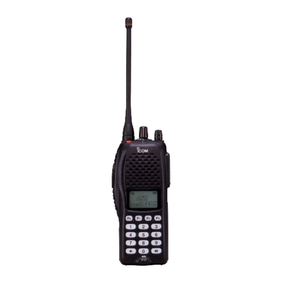
FOREWORD Thank you for purchasing the IC-F31GT/IC-F31GS, IC-F31GT-L/ IC-F31GS-L, IC-F41GT/IC-F41GS vhf / uhf transceivers READ ALL INSTRUCTIONS carefully and completely before using the transceiver. SAVE THIS INSTRUCTION MANUAL–This instruction manual con- tains important operating instructions for the transceiver. EXPLICIT DEFINITIONS...
The transceiver construction is water resistant, not waterproof. Icom, Icom Inc. and the Icom logo are registered trademarks of Icom Incorpo- rated (Japan) in Japan, the United States, the United Kingdom, Germany, France, Spain, Russia and/or other countries.
See the supplied leaflet for details. D Antenna The antenna screws onto the transceiver as illustrated at right. ✔ For IC-F31GT-L/GS-L The most suitable flexible antenna should be purchased according to programmed fre- quency parameters. See page 23 for details.
PANEL DESCRIPTION Switches, controls, keys and connectors Speaker Microphone Programmable key reference F0 (Red) F1 (Black) F2 (Black) F3 (Black)
Page 7
]/[P ]/[P ]/[P Can each be programmed for one of several functions by your Icom Dealer. u 10-KEY PAD (10-key versions only) Used to enter DTMF codes, the operating channel, etc. i FUNCTION DISPLAY Displays a variety of information, such as, operating channel number/names, 5-tone code, remaining battery power, DTMF numbers, transmit output power setting, Audible indication, etc.
PANEL DESCRIPTION n Function display q SIGNAL STRENGTH METER Indicates relative signal strength level. w BANK NUMBER INDICATOR Indicates operating bank (channel group) number. e LOW POWER INDICATOR Appears when low output power is selected. r MULTI-FUNCTION INDICATOR Indicates operating channel number, channel names, 5-tone code, etc., according to operating condition.
BATTERY PACKS n Battery pack replacement Before replacing the battery pack, the volume control MUST be ro- tated fully counterclockwise, until a click is heard, to turn the power OFF. • Slide the battery release forward, then pull the battery pack up- ward with the transceiver facing away from you.
BATTERY PACKS n Battery cautions • CAUTION! NEVER short terminals (or charging terminals) of the battery pack. Also, current may flow into nearby metal objects such as a necklace, so be careful when placing battery packs (or the transceiver) in handbags, etc. Simply carrying with or placing near metal objects such as a neck- lace, etc.
BATTERY PACKS n Battery charging D Rapid charging with the BC-119N The optional BC-119N provides rapid charging of the battery pack. The followings are additionally required: • One AD-101 (purchase separately) • An AC adapter (may be supplied with the BC-119N depending on version) Turn power OFF.
Page 12
BATTERY PACKS D Rapid charging with the BC-121N+AD-101 The optional BC-121N allows up to 6 battery packs to be charged simultaneously. The followings are additionally required. • Six AD-101. • An AC adapter (BC-157) or the DC power cable (OPC-656) Turn power OFF.
BATTERY PACKS n Charging NOTE Prior to using the transceiver for the first time, the battery pack must be fully charged for optimum life and operation. • Recommended temperature range for charging: Between +10°C and +40°C • Use the supplied charger or optional charger (BC-119N/BC-121N/ BC-144N for rapid charging, BC-137 #11/BC-146 for regular charging) only.
BATTERY PACKS n Battery case (Option) When using the optional battery case, install 6 × AA (LR6) size alkaline batteries as illustrated below. CAUTION: • Use alkaline batteries only. • When installing batteries, make sure they are all the same brand, type and capacity.
PROGRAMMABLE FUNCTIONS n General In the following explanations, programmable function names are bracketed, the specific switch used to activate the function depends on programming. D KEYPAD LOCK FUNCTION This function locks access to all programmable switches (except the switch assigned for the lock function). Push and hold the [Lock] switch for 1 sec.
Page 16
PROGRAMMABLE FUNCTIONS D HIGH/LOW OUTPUT POWER This function selects high or low output power for a channel. Push the [High/Low] switch to change transmit output power be- tween high, low1 and low2 output power. • “ ” appears when low1 or low2 output power is selected. D SCRAMBLER FUNCTION (An optional UT-109 #02* or UT-110 #02* is required.) This function provides higher communication security.
Page 17
PROGRAMMABLE FUNCTIONS D MONITOR AUDIBLE FUNCTION The monitor function allows you to open the transceiver’s squelch manually to check whether a channel is busy or not. The trans- ceiver has 2 conditions for receive standby: Audible condition: This condition mutes audio ONLY when no carrier is present.
Page 18
PROGRAMMABLE FUNCTIONS D DTMF TRANSMISSION This function allows you to send a pre-programmed DTMF code to control a repeater, open another transceiver’s squelch, etc. Manual transmission: Push desired digit keys in sequence while pushing [PTT]. • Pushing [PTT] may not be necessary depending on programming. Automatic pre-programmed transmission: q Push the [DTMF Autodial] switch to select DTMF autodial mode, then push [CH Up] or [CH Down] to select the desired channel.
PROGRAMMABLE FUNCTIONS D DISPLAY LIGHTING The function display has 3 backlight conditions. : Backlight stays ON continuously. : No backlight. AUTO : When any key is pushed, the backlight turns ON for 5 sec. automatically.
CONVENTIONAL OPERATION n Receiving and transmitting NOTE: Transmitting without an antenna may damage the trans- ceiver. See p. 1 for antenna attachment. Turn power ON as described on p. 3. Receiving: q Push [CH Up]/[CH Down], or rotate [SEL] to select a channel. w Listen for a transmission and adjust [VOL] to a comfortable lis- tening level.
CONVENTIONAL OPERATION n Call procedure When your system employs tone signalling (excluding CTCSS and , the call procedure may be necessary prior to voice trans- DTCS) mission. The tone signalling employed may be a selective calling system which allows you to call specific station(s) only and prevent unwanted stations from contacting you.
CONVENTIONAL OPERATION n Tx code channel selection Your radio may be programmed for Tx code channel selection. In this case, you can choose a Tx code channel to be transmitted when using the selective calling function (p. 17). Push [Tx Code CH Up/Down] (assigned to one of the dealer-pro- grammable switches) to select the desired Tx code channel.
OTHER FUNCTIONS DTMF PAGER/CODE SQUELCH D DTMF pager This function uses DTMF tones for calling and can be used as a “common pager” to inform you that one of your group has called even if the operator is temporarily away from the transceiver. •...
OPTIONAL UNIT INSTALLATION You can install up to two optional units in the transceiver. Installation q Unscrew nut a, and remove the knobs. w Unscrew screw b and 2 screws c, then remove the multi-con- nector cover and rear panel. e Unscrew 2 screws d, then remove the multi-connector.
CLONING Cloning Cloning allows you to quickly and easily transfer the programmed contents from one transceiver to another transceiver. Or, program data from a PC into a transceiver, using the optional CS-F30G cloning software D PC-to-transceiver cloning Please refer to the HELP file that comes with the CS-F30G clon ing software CAUTION: Improper cloning operation will cause a cloning error.
OPTIONS D BATTERY PACKS/CASE • BP-208N battery case Battery case for 6 AA (LR6) alkaline batteries. • BP-210N Ni-MH battery pack Voltage : 7.2 V Capacity : 1650 mAh D RAPID CHARGERS • BC-119N + AD-101 desktop charger charger adapter + BC-145S ac adapter Charging period: 2.0 hrs.
Approved Icom optional equipment is designed for optimal perfor- mance when used with an Icom transceiver. Icom is not responsible for the destruction or damage to an Icom transceiver in the event the Icom transceiver is used with equip- ment that is not manufactured or approved by Icom.
ABOUT CE CE Versions of the IC-F31GT/IC-F31GS, IC-F31GT-L/IC-F31GS-L, IC-F41GT/IC-F41GS which display the “CE” symbol on the serial num- ber label, comply with the essential requirements of the European Radio and Telecommunication Terminal Directive 1999/5/EC. This warning symbol indicates that this equipment...
Need help?
Do you have a question about the IC-F31GT and is the answer not in the manual?
Questions and answers