Icom IC-F3161DT Instruction Manual
Vhf transceiver; uhf transceiver
Hide thumbs
Also See for IC-F3161DT:
- Instruction manual (40 pages) ,
- Instruction manual (40 pages) ,
- Adjustment (10 pages)
Table of Contents
Advertisement
Advertisement
Table of Contents

Related Manuals for Icom IC-F3161DT


Summary of Contents for Icom IC-F3161DT
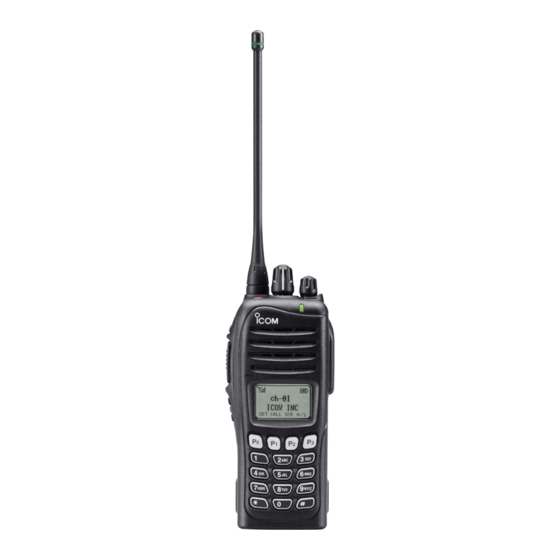
- Page 1 INSTRUCTION MANUAL VHF TRANSCEIVER iF3161DT iF3161DS UHF TRANSCEIVER iF4161DT iF4161DS This device complies with Part 15 of the FCC Rules. Op- eration is subject to the condition that this device does not cause harmful interference. The photo shows the UHF transceiver.
-
Page 2: Explicit Definitions
Communications Equipment. The user of this Technology is explicitly prohibited from attempting to ex- Icom, Icom Inc. and the Icom logo are registered trademarks of Icom Incor- tract, remove, decompile, reverse engineer, or disassemble porated (Japan) in Japan, the United States, the United Kingdom, Germany, the Object Code, or in any other way convert the Object Code France, Spain, Russia and/or other countries. -
Page 3: Precautions
The transceiver is water resistant, and options. Using them invalidates the transceivers FM ap- not waterproof. proval. CAUTION: Changes or modifications to this transceiver, not expressly approved by Icom Inc., could void your author- ity to operate this transceiver under FCC regulations. -
Page 4: Fcc Information
BP-232FM clean to avoid any risk of ignition due to the build-up of electrostatic charges. Repair of Icom radios should only be carried out by autho- rized Icom distributors. In particular, repair of FM approved ONLY... -
Page 5: Table Of Contents
TABLE OF CONTENTS IMPORTANT ................i ■ Emergency transmission ..........17 EXPLICIT DEFINITIONS ............i ■ Automatic Key Lock function ........18 VOICE CODING TECHNOLOGY .......... i ■ Priority A channel selection ........18 PRECAUTIONS ..............ii 4 BATTERY CHARGING ..........19−23 FCC INFORMATION ............iii ■... -
Page 6: Accessories
ACCESSORIES ■ Supplied accessories ■ Accessory attachments D Flexible antenna The following accessories are supplied. Connect the supplied flexible antenna to the antenna connector. Flexible antenna Battery pack Belt clip (This illustration is CAUTION: for the UHF type.) • NEVER carry the transceiver by holding only the antenna. -
Page 7: D Battery Pack
ACCESSORIES D Battery pack D Belt clip To attach the battery pack: To attach the belt clip: Slide the battery pack on the back of the transceiver in the direc- q Remove the battery pack if it is attached. tion of the arrow (q), then lock it with the battery release button. w Slide the belt clip in the direction of the arrow until the belt •... -
Page 8: Accessories
ACCESSORIES D Connector cover To detach the connector cover: To attach the connector cover: q Insert the connector cover into the multi-connector. q Remove the screw using a phillips screwdriver. w Detach the connector cover for the optional equipment w Tighten the screw. connector. -
Page 9: Panel Description
PANEL DESCRIPTION ■ Front panel r DEALER-PROGRAMMABLE KEY [Side1] Desired function can be programmed by your dealer. (p. 6) t PTT SWITCH [PTT] Speaker Push and hold to transmit; release to receive. y DEALER-PROGRAMMABLE KEYS [Side2]/[Side3] Desired function can be programmed independently by Microphone your dealer. -
Page 10: Function Display
PANEL DESCRIPTION ■ Function display !0 MULTI-CONNECTOR Connect an optional equipment. Connector cover NOTE: Attach the connec- tor cover when the optional equipment is not used. See page 3 for details. CALA TXCU TXC q SIGNAL STRENGTH INDICATOR !1 BUSY/TRANSMIT INDICATOR Indicates relative signal strength level. -
Page 11: Programmable Function Keys
[Side2], [Side3], [P0], [P1], [P2] and [P3] programmable cording to the pre-programming. function keys. Consult your Icom dealer or system operator for details con- u CALL CODE MEMORY INDICATOR cerning your transceivers programming. Appears when the call code memory is selected. - Page 12 PANEL DESCRIPTION ZONE KEY “ZONE” SCAN ADD/DEL (TAG) KEY “SCAD” Push this key, then push [CH Up] or [CH Down] to select ➥ Push to add channel to, or delete it from the current scan the desired zone. When [Rotary selector] selects “operating group.
- Page 13 PANEL DESCRIPTION MEMORY CH 1/2/3/4 KEYS “CH1” “CH2” “CH3” “CH4” LONE WORKER KEY “LONE” Push to select the memory channels 1 to 4 directly. Push to turn the Lone Worker function ON or OFF. • If the Lone Worker function is activated, the Emergency function is automatically turned ON after the specified time period has passed MONI KEY “MON”...
- Page 14 PANEL DESCRIPTION TALK AROUND KEY “TA” EMERGENCY KEY “EMR” Push to turn the talk around function ON and OFF. Push and hold to transmit the emergency call. • The talk around function equalizes the transmit frequency to the • The emergency call transmits with beeps; the display does not receive frequency for transceiver-to-transceiver communication.
-
Page 15: Panel Description
PANEL DESCRIPTION TX CODE CHANNEL UP/DOWN KEYS “TXCU” “TXCD” OPT OUT KEYS “OP1” “OP2” “OP3” Push to select a TX code channel directly. Push to control the output signal level from the optional unit connector. ID-MEMORY SELECT KEY “IDMS” OPT MOMENTARY KEYS “O1M” “O2M” “O3M” ➥... -
Page 16: Basic Operation
BASIC OPERATION ■ Turning power ON ■ Channel selection Prior to using the transceiver for the first time, the battery Several types of channel selections are available. Methods pack must be fully charged for optimum life and operation. may differ according to your system set up. (p. - Page 17 BASIC OPERATION AUTOMATIC SCAN TYPE: Channel setting is not necessary for this type. When turning power ON, the transceiver automatically starts scanning. Scanning stops when receiving a call. * Depending on the pre-setting. When [Rotary selector] selects “Operating channel,” [CH Up]/[CH Down] are not available.
-
Page 18: Call Procedure
BASIC OPERATION ■ Call procedure ■ Receiving and transmitting When your system employs tone signalling (excluding CTCSS CAUTION: Transmitting without an antenna may damage and DTCS), this call procedure may be necessary prior to voice the transceiver. See page 1 for accessory attachments. transmission. -
Page 19: D Transmitting Notes
BASIC OPERATION D Transmitting notes D TX code channel selection • Transmit inhibit function If the transceiver has [TX Code CH Select] assigned to it, The transceiver has several inhibit functions which restrict the indication can be toggled between the operating channel transmission under the following conditions: number (or name) and TX code channel number (or name). -
Page 20: D Dtmf Transmission
BASIC OPERATION D TX code number edit USING [TX CODE ENTER] KEY: (PMR operation only) q After pushing [TX Code CH Select], push [CH Up] or [CH If the transceiver has [TX Code CH Select] or [TX Code Down], or push [TX Code CH Up] or [TX Code CH Down] Enter] assigned to it, TX code contents can be edited within to select the desired TX code channel. -
Page 21: User Set Mode
BASIC OPERATION ■ User set mode ■ Scrambler function The User Set mode allows you to set seldom-changed set- The voice scrambler function provides private communication tings. If the transceiver has [User Set Mode] assigned to it, between stations. All versions have a built-in frequency inver- you can “customize”... -
Page 22: Emergency Transmission
BASIC OPERATION ■ Emergency transmission D NOTES When [Emergency] is pushed for the specified time period*, the emergency signal is transmitted once, or repeatedly, on Depending on the presetting, the following functions are auto- the specified emergency channel. matically activated. Ask your dealer for details. •... -
Page 23: Automatic Key Lock Function
BASIC OPERATION ■ Automatic Key Lock function When [Lock] is assigned to any key and the Automatic Key Lock timer is pre-programmed* by your dealer, the key lock function can be automatically turned ON after the specified time period has passed without operation during standby condition. While the lock function is ON, push and hold [Lock] for 1 sec. -
Page 24: Battery Charging
• R DANGER! Use and charge only specified Icom battery • R DANGER! DO NOT expose the battery to rain, snow, packs with Icom radios or Icom charger. Only Icom battery seawater, or any other liquids. - Page 25 If • R DANGER! NEVER charge the battery pack in areas with any of these conditions occur, contact your Icom dealer or extremely high temperatures, such as near fires or stoves, distributor.
-
Page 26: Optional Battery Chargers
BATTERY CHARGING ■ Optional battery chargers D Regular charging with the BC-171 D Rapid charging with the BC-160 The optional BC-171 provides regular charging of the Li-ion The optional BC-160 provides rapid charging of the Li-ion battery pack. battery pack. Charging period: Approximately 10 hours (with BP-232FM) Charging period: Approximately 3 hours (with BP-232FM) AC adapter... - Page 27 BATTERY CHARGING D AD-106 installation D Rapid charging with the BC-119N+AD-106 The AD-106 must be installed into the The optional BC-119N provides rapid charging of the Li-ion charger adapter BC-119N or BC-121N before battery charging. battery pack. Charging period: Approximately 3 hours (with BP-232FM) q Connect the AD-106 and the BC-119N/ charger adapter...
- Page 28 BATTERY CHARGING D Rapid charging with the BC-121N+AD-106 IMPORTANT: Battery charging caution Ensure the guide tabs on the battery pack are correctly The optional BC-121N allows up to 6 battery packs to be aligned with the guide rails inside the charger adapter. charged simultaneously.
-
Page 29: Swivel Belt Clip
SWIVEL BELT CLIP ■ MB-93 contents r Clip the belt clip to a part of your belt. And insert the transceiver into the belt clip until the base clip inserted fully into the groove. Qty. q Belt clip ................1 w Base clip ................1 t Once the transceiver is locked in place, it swivels as illus- ■... -
Page 30: To Detach
SWIVEL BELT CLIP ■ To detach q Turn the transceiver upside down in the direction of the CAUTION: arrow and pull out from the belt clip. HOLD THE TRANSCEIVER TIGHTLY, WHEN HANGING OR DETACHING THE TRANSCEIVER FROM THE BELT CLIP. Otherwise the transceiver may not be attached to the holder or swivel properly if the transceiver is accidentally dropped and the base clip is scratched or damaged. -
Page 31: Speaker Microphone
SPEAKER MICROPHONE ■ Optional HM-169IS description ■ To attach Attach the connector of the speaker-microphone into the multi Microphone connector on the transceiver and tighten the screw. PTT SWITCH Push and hold to Speaker transmit; release to receive. CAUTION: Attach Belt clip multi connector snugly, but do not overtighten. -
Page 32: Options
OPTIONS D BATTERY PACKS D BELT CLIPS • MB-93 swivel belt clip Battery pack Voltage Capacity Battery life* • MB-94 belt clip 1900 mAh (min.) BP-232FM 7.4 V 12 hrs. Exclusive alligator-type belt clip. 2000 mAh (typ.) • MB-96N/96F leather belt hanger * When the power save function is turned ON, and the operating pe- D OTHER OPTIONS riods are calculated under the following conditions;... - Page 33 VOX/PTT select switch performance when used with an Icom transceiver. Icom is not responsible for the destruction or damage to an Icom transceiver in the event the Icom transceiver is used with equipment that is not manufactured or approved by...
-
Page 34: Vox Gain
OPTIONS VOX gain and delay adjustment • VOX Delay q Attach the connector of the VS-1SC into the multi-connec- The VOX delay time can be set from 0.5 to 3.0 sec. (0.5 sec. tor on the transceiver and tighten the screw. step) for a convenient interval before returning to receive. -
Page 35: Safety Training Information
• ALWAYS keep the antenna at least 2.5 cm (1 inch) away sure to Radio Frequency Electromagnetic Fields, 3 kHz to from the body when transmitting and only use the Icom 300 GHz. belt-clips listed on page 27 when attaching the radio to your •... - Page 36 RF de la FCC et d’IC, pour une «utilisation grand pu- persons are fully aware of the potential for exposure and can blic». En outre, votre radio Icom satisfait les normes et directives exercise control over their exposure.
- Page 37 • TOUJOURS tenir l’antenne éloignée d’au moins 2,5 cm de votre corps au moment d’émettre et utiliser uniquement l’at- tache pour ceinture Icom illustrée à la p. 27, lorsque vous at- tachez la radio à votre ceinture, ou à autre chose, de façon à...
- Page 38 MEMO...
- Page 39 MEMO...
- Page 40 A-6831H-1EX-w Printed in Japan © 2010–2013 Icom Inc. 1-1-32 Kamiminami, Hirano-ku, Osaka 547-0003, Japan Printed on recycled paper with soy ink.
Need help?
Do you have a question about the IC-F3161DT and is the answer not in the manual?
Questions and answers