Table of Contents
Advertisement
Owner's Manual
Autoranging
Industrial Multimeter
Model No.
82005
CAUTION: Read, understand and
follow Safety Rules and Operating
Instructions in this manual before
using this product.
Sears, Roebuck and Co., Hoffman Estates, IL 60179
www.craftsman.com
Safety
Operation
Maintenance
Español
061510
Advertisement
Table of Contents

Related Manuals for Craftsman 82005


Summary of Contents for Craftsman 82005
- Page 1 Owner's Manual Autoranging Industrial Multimeter Model No. 82005 Safety CAUTION: Read, understand and Operation follow Safety Rules and Operating Instructions in this manual before Maintenance using this product. Español Sears, Roebuck and Co., Hoffman Estates, IL 60179 www.craftsman.com...
-
Page 2: Table Of Contents
NEAREST SEARS STORE OR OTHER CRAFTSMAN OUTLET IN THE UNITED STATES, and Sears will replace it, free of charge. If this CRAFTSMAN MULTIMETER is used for commercial or rental purposes, this warranty applies for 90 days from the date of purchase. -
Page 3: Safety Instructions
WARNING: USE EXTREME CAUTION IN THE USE OF THIS DEVICE. Improper use of this device can result in injury or death. Follow all safeguards suggested in this manual in addition to the normal safety precautions used in working with electrical circuits. DO NOT service this device if you are not qualified to do so. -
Page 4: Safety Symbols
SAFETY SYMBOLS This symbol adjacent to another symbol, terminal or operating device indicates that the operator must refer to an explanation in the Operating Instructions to avoid personal injury or damage to the meter. This WARNING symbol indicates a WARNING potentially hazardous situation, which if not avoided, could result in death or serious injury. -
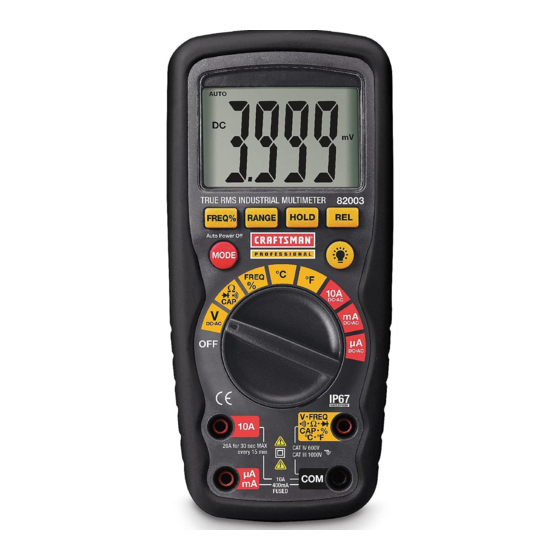
Page 5: Control, Jacks, & Display
CONTROLS, JACKS, AND DISPLAY 1. 4,000 count LCD display 2. RANGE button 3. Hz and % button 4. Mode button 5. Function switch 6. mA, µA and 10A input jacks 7. COM input jack 8. Positive input jack 9. Backlight button 10. -
Page 6: Specifications
SPECIFICATIONS Resolution Function Range Accuracy (0.5% reading + 2 digits) DC Voltage 400mV 0.1mV 0.001V (1.2% reading + 2 digits) 0.01V 400V 0.1V (1.5% reading + 2 digits) 1000V (2.0% reading + 10 digits) AC Voltage 400mV 0.1mV 0.001V (2.0% reading + 5 digits) 0.01V 400V 0.1V... - Page 7 (5% reading + 5 digits) 100F 0.1F Frequency 5.999Hz 0.001Hz (1.5% reading + 1 digits) 59.99Hz 0.01Hz 599.9Hz 0.1Hz 5.999kHz 0.001kHz (1.2% reading + 3 digits) 59.99kHz 0.01kHz 599.9kHz 0.1kHz 5.999MHz 0.001MHz (1.5% reading + 4 digits) 9.999MHz 0.001MHz Sensitivity: 0.5V rms <500kHz; 3V rms >500kHz (1.2% reading + 2 digits) Duty Cycle 0.1 to...
- Page 8 Polarity Automatic (no indication for positive); Minus (-) sign for negative Measurement Rate 2 times per second, nominal Low Battery Indication “ ” is displayed if battery voltage drops below operating voltage Battery One 9 volt (NEDA 1604) battery Fuses mA, µA ranges;...
-
Page 9: Battery Installation
BATTERY INSTALLATION BATTERY INSTALLATION WARNING: To avoid electric shock, disconnect the test leads from any source of voltage before removing the battery cover. 1. Turn power off and disconnect the test leads from the meter. 2. Open the rear battery cover by removing two screws (B) using a Phillips head screwdriver. -
Page 10: Fuse Installation
REPLACING THE FUSES WARNING: To avoid electric shock, disconnect the test leads from any source of voltage before removing the fuse cover. 1. Disconnect the test leads from the meter. 2. Remove the battery cover (two “B” screws) and the battery. 3. -
Page 11: Operating Instructions
OPERATING INSTRUCTIONS WARNING: Risk of electrocution. High-voltage circuits, both AC and DC, are very dangerous and should be measured with great care. NOTES: 1. ALWAYS turn the Function switch to the OFF position when the meter is not in use. 2. -
Page 12: Ac Voltage Measurements
AC VOLTAGE (FREQUENCY, DUTY CYCLE) MEASUREMENTS WARNING: Risk of Electrocution. The probe tips may not be long enough to contact the live parts inside some 240V outlets for appliances because the contacts are recessed deep in the outlets. As a result, the reading may show 0 volts when the outlet actually has voltage on it. -
Page 13: Dc Current Measurements
DC CURRENT MEASUREMENTS CAUTION: Do not make 20A current measurements for longer than 30 seconds. Exceeding 30 seconds may cause damage to the meter and/or the test leads. 1. Insert the black test lead banana plug into the negative COM jack. 2. -
Page 14: Ac Current Measurements
AC CURRENT (FREQUENCY, DUTY CYCLE) MEASUREMENTS CAUTION: Do not make 20A current measurements for longer than 30 seconds. Exceeding 30 seconds may cause damage to the meter and/or the test leads. 1. Insert the black test lead banana plug into the negative COM jack. -
Page 15: Resistance And Continuity Measurements
RESISTANCE MEASUREMENTS WARNING: To avoid electric shock, disconnect power to the unit under test and discharge all capacitors before taking any resistance measurements. Remove the batteries and unplug the line cords. 1. Set the function switch to the ΩCAP position. 2. -
Page 16: Diode Tests
DIODE TEST 1. Set the function switch to the Ω CAP position. 2. Insert the black test lead banana plug into the negative COM jack and the red test lead banana plug into the positive V jack. 3. Press the MODE button to indicate on the display. -
Page 17: Capacitance Measurements
CAPACITANCE MEASUREMENTS WARNING: To avoid electric shock, disconnect power to the unit under test and discharge all capacitors before taking any capacitance measurements. Remove the batteries and unplug the line cords. 1. Set the rotary function switch to the Ω CAP position. -
Page 18: Autoranging
FREQUENCY SENSITIVITY (ELECTRICAL) The frequency sensitivity is range dependent when the Hz function is selected while in the voltage or current measuring mode. Below are typical sensitivities for the “electrical” measurement modes. Range Sensitivity Frequency ( DC/AC ) bandwidth ≥1.5V rms 5Hz~10kHz ≥10V rms 40V, 400V... -
Page 19: Relative, Backlight, Hold, Auto Off, Low Battery
RELATIVE MODE The relative measurement feature allows you to make measurements relative to a stored zero reference value. A reference voltage, current, etc. can be stored and measurements made in comparison to that value. The displayed value is the difference between the reference value and the measured value. -
Page 20: Maintenance
MAINTENANCE WARNING: To avoid electric shock, disconnect the test leads from any source of voltage before removing the back cover or the battery or fuse covers. WARNING: To avoid electric shock, do not operate your meter until the battery and fuse covers are in place and fastened securely. - Page 21 REPLACING THE BATTERY WARNING: To avoid electric shock, disconnect the test leads from any source of voltage before removing the battery door. 1. When the battery become exhausted or drops below the operating voltage, the low battery icon will appear in the lower left of the LCD display.
-
Page 22: Troubleshooting
TROUBLESHOOTING There may be times when your meter does not operate properly. Should that happen, please follow the following steps: 1. Always read all the instructions in this manual before use. 2. If You Do Not Understand How the Meter Works, purchase the instructional book “Multitesters and Their Use for Electrical Testing”...
Need help?
Do you have a question about the 82005 and is the answer not in the manual?
Questions and answers