Allied Telesis AR415S Hardware Reference Manual
Ar400 series
Hide thumbs
Also See for AR415S:
- Installation and safety manual (54 pages) ,
- Release note (99 pages) ,
- Installation and safety manual (56 pages)
Table of Contents
Advertisement
Quick Links
Advertisement
Table of Contents

Related Manuals for Allied Telesis AR415S


Summary of Contents for Allied Telesis AR415S
- Page 1 AR400 Series Router Hardware Reference AR415S AR440S AR441S AR442S AR450S...
- Page 2 The information provided herein is subject to change without notice. In no event shall Allied Telesis Inc. be liable for any incidental, special, indirect, or consequential damages whatsoever, including but not limited to lost profits, arising out of or related to this manual or the information contained herein, even if Allied Telesis Inc.
-
Page 3: Table Of Contents
Hardware Reference Contents Devices Covered By This Document ..............4 Hardware Overview ..................4 AR415S Secure Modular Router ................ 5 Hardware Features ..................5 Environmental Conditions ................6 Power Supply ..................... 6 LEDs and What They Mean ................. 7 AR440S and AR441S ADSL Routers ..............8 Hardware Features .................. -
Page 4: Devices Covered By This Document
ISDN (PRI E1/T1, BRI S/T, or BRI U), Ethernet, Voice over IP, synchronous, or asynchronous ports. The AR415S has an Eth port that can be used for a dedicated WAN connection. The AR450S has dedicated WAN and DMZ eth ports, and two asynchronous ports. -
Page 5: Ar415S Secure Modular Router
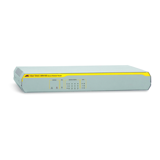
For pin wiring and default communication settings, see “Asynchronous Interfaces” on page ■ one PIC bay Front and rear panels of the AT-AR415S router are shown in the following figure. AR415S Secure Modular Router STATUS SWITCH PORTS... -
Page 6: Environmental Conditions
AT-AR023 SYN PIC, one synchronous port with universal 50-way AMPLIMITE connector When installed in an AR415S router and operating in V.35 mode, synchronous PICs have full V.35 functionality, but their output voltages may not be within the voltage range set by the V.35 specification. -
Page 7: Leds And What They Mean
Hardware Reference LEDs and What They Mean The following table shows functions of the AR415S router LEDs. State Function Green The router is receiving power and the power switch is Amber Lit briefly during router start up, or the router is malfunctioning. -
Page 8: Ar440S And Ar441S Adsl Routers
AR400 Series Router AR440S and AR441S ADSL Routers Each AR440S or AR441S router provides: ■ AR440S: One Asynchronous Digital Subscriber Line (ADSL) Annex A port ■ AR441S: One Asynchronous Digital Subscriber Line (ADSL) Annex B port ■ five 10/100 Mbps full duplex, Layer 2 switched Ethernet LAN ports All LAN ports have Auto-MDI, however if Auto-MDI is turned off, then all ports are hard-wired as MDI-X. -
Page 9: Environmental Conditions
Hardware Reference ADSL interfaces The ADSL port has an RJ-11 connector, and supports Dying Gasp. The speed depends on the DSLAM to which the router is connected, and the length and interference on the cable connecting them. The following table shows the pin wiring for the ADSL interface. -
Page 10: Power Supply
AR400 Series Router Power Supply The routers have a universal AC input connector and a power switch on their rear panel. The routers require a power input of 100 VAC to 240 VAC and 50 Hz to 60 Hz. Caution Some interfaces that may be installed in the router are not transformer isolated. -
Page 11: Ar442S Shdsl Router
Hardware Reference AR442S SHDSL Router Each AR442S router provides: ■ One 2-pair (4-wire) SHDSL port (Single-pair High-speed Digital Subscriber Line, also known as Symmetric High bit-rate Digital Subscriber Loop) ■ Five 10/100 Mbps full duplex, Layer 2 switched Ethernet LAN ports. All LAN ports have Auto-MDI, however if Auto-MDI is turned off, then all ports are hard-wired as MDI-X. - Page 12 AR400 Series Router SHDSL interface The SHDSL interface transmits and receives data compliant with ITU-T G.991.2 recommendations as either CPE or CO. The data rates depend on the DSLAM to which the router is connected, and the length and interference on the cable connecting them.
-
Page 13: Environmental Conditions
Hardware Reference Environmental Conditions ■ operating temperature range: 0 ºC to 50 ºC (32 ºF to 122 ºF) ■ storage temperature range: -25 ºC to 70 ºC (-13 ºF to 158 ºF) ■ relative humidity range - Storage: 5 to 95% non-condensing ■... -
Page 14: Leds And What They Mean
AR400 Series Router LEDs and What They Mean The following table shows functions of the AR442S LEDs. State Function Power Green The router is receiving power and the power switch is ON. System Lit briefly during router start up, or the router is malfunctioning. -
Page 15: Ar450S Router
The AR450S has 64 MB of SDRAM provided on a single DIMM. 128 MB and Memory (RAM) 256 MB ECC SDRAM are also supported. See your authorised Allied Telesis distributor or reseller for upgrade options. Other supplier’s DIMMs are not approved, and therefore not supported, but may function correctly. -
Page 16: Environmental Conditions
AR400 Series Router The DRAM and FLASH fields show the amounts of DRAM and flash memory, respectively. Encryption processor Some encryption options require feature licences. The on-board encryption processor has the following features: • single and triple DES, and AES symmetric encryption algorithms •... -
Page 17: Asynchronous Interfaces
AR415S base asyn port. For information about asynchronous interfaces on the AR024 ASYN 4 PIC, see the Port Interface Card Hardware Reference. AR415S The asynchronous interfaces on the AR415S router. The pin wiring is shown in the following table. Pin* Function... -
Page 18: Expansion Options
* Pins are numbered from left to right. Expansion Options You can expand the interface options of your AR440S, AR441S, AR442S, and AR415S routers using Port Interface Cards (PICS). Port Interface Cards (PICs) You can install a PIC (Port Interface Card) in any AR400 Series routers except the AR450S. -
Page 19: Memory Options
If the flash memory size is lower than expected, then the router’s boot process has not correctly detected or recognised the flash memory’s presence. If recognition fails, contact your authorised Allied Telesis distributor or reseller. If the flash is recognised, display flash memory size, device type, and location... - Page 20 AR400 Series Router Figure 3: Example output from the show flash physical command for an AR450S total size .... 16 MBytes available to FFS ... 15 MBytes available to boot .. 1 MBytes device type ... 28F128 devices ....1 location ....
-
Page 21: Cables And Loopback Plugs
The pinout for the asyn ports on an AR024 ASYN 4 PIC is different from the pinout of the AR415S base asyn port. For information about cables to connect to an AR024 ASYN 4 PIC, see the Port Interface Card Hardware Reference. - Page 22 Cable version 1.0. modem_ar750_db9m RJ-45 to DB9 female To connect the asyn port on an AR415S to a PC, terminal or router with a DB9 male connector wired as DCE, use an RJ-45 to DB9 female cable wired as in the cable following diagram.
- Page 23 Cable version 1.0. modem_ar750 RJ-45 to DB25 To connect the asyn port on an AR415S to a PC, terminal or router with a DB25 female cable male connector wired as DCE, use an RJ-45 to DB25 female cable wired as in the following diagram.
- Page 24 AR400 Series Router RJ-45 to mini DIN-8 To connect the asyn port on an AR415S to a Macintosh mini DIN-8 port, use an cable RJ-45 to mini DIN-8 cable wired as in the following diagram. RJ-45 MiniDin (to Macintosh) (to router) ←...
- Page 25 Hardware Reference DB9 female to To connect the DB9 male asyn port on an AR440S, AR441S, AR442S, or AR450S DB9 male cable to a modem with a DB9 female connector wired as DCE, use a straight-through cable wired as in the following diagram. DB9 Female DB9 Male (to router/DTE)
- Page 26 AR400 Series Router DB9 female to DB25 To connect the DB9 male asyn port on an AR440S, AR441S, AR442S, or AR450S female cable to a PC, terminal or router with a DB25 male connector wired as DCE, use a DB9 female to DB25 female null modem cable wired as in the following diagram.
- Page 27 Hardware Reference DB9 female to DB25 To connect the DB9 male asyn port on an AR440S, AR441S, AR442S, or AR450S male cable to a modem with a DB25 female connector wired as DCE, use a cable wired as in the following diagram. DB9 Female DB25 Male (to router/DTE)
-
Page 28: Loopback Plugs For Testing Interfaces
(available from your authorised Allied Telesis distributor or reseller) to be used in conjunction with the Test Facility. Loopback plug for To test an asynchronous (RS232/Console) port on an AR415S, use a loopback RJ-45 asyn port plug as described in the following figure. - Page 29 Hardware Reference Loopback plug for To test an eth or switch port, use a loopback plug as described in the following RJ-45 switch or eth figure. port Twisted Pair (TP) Loopback Plug (RJ45 connector) End view of plug connected connected •Not TPLOOP C613-03086-00 REV G...
-
Page 30: Using At-Tftp Server
Install it now from the router’s Documentation and Tools CD-ROM. To install AT-TFTP server, choose AT-TFTP Server from the Start > Programs > Allied Telesis > AT-TFTP Server menu. To set preferences for the AT-TFTP Server. Select "Options" from the File menu to display the "Set Preferences" dialog box. -
Page 31: Using Windows Terminal And Hyperterminal
Hardware Reference Using Windows Terminal and HyperTerminal You can use a PC running terminal emulation software as the manager console, instead of a terminal. There are many terminal emulation applications available for PCs, but the most readily available are the Terminal and HyperTerminal applications included in Microsoft Windows 98, 2000, and XP Professional. - Page 32 AR400 Series Router In the “Connect using” field on the Connect To dialog box, select the COM port on the PC used to connect to the router. and click the OK button. In the COMn Properties dialog box, set port parameters as follows, and click the OK button.
- Page 33 Hardware Reference From the main HyperTerminal window, select Properties from the File menu. Click the Settings tab, and set the Properties dialog box as follows. Click ASCII Setup to display the ASCII Setup dialog box, and ensure the following options are not selected: •...
-
Page 34: How The Router Starts Up
AR400 Series Router Save the current session by selecting Save from the File menu on the main HyperTerminal window. This creates a connection icon with the name you assigned in the HyperTerminal group. To use the configuration, double-click the connection icon. When the HyperTerminal window appears, press the Enter key several times;... - Page 35 Hardware Reference Start-up process When the router starts up following either a power cycle or an operator- initiated reboot (using the restart reboot command in the Upgrade chapter, Software Reference), the following sequence of operations is performed: Perform start-up self tests. Load the flash boot block version as the INSTALL boot into the router’s RAM.
- Page 36 AR400 Series Router Router start-up If a key is not pressed within a few seconds, the start-up process continues and sequence keystrokes all steps in the start-up sequence are executed. Pressing certain keys on the terminal immediately after the “Force EPROM download” message is displayed changes the router start-up process as described in the following table.
- Page 37 The load of the vector table from ROM to RAM failed. The load is retried a number of times. Each time a failure occurs the ERROR message is displayed. If the maximum number of attempts is reached, the FAIL message is displayed. Contact your authorised Allied Telesis distributor or reseller. INFO: Initial download successful.
-
Page 38: Test Facility
“Loopback Plugs for Testing Interfaces” on page The following examples show how to test specific interfaces. If a test fails, contact your authorised Allied Telesis distributor or reseller. To display test results, use the command: show test The following figure shows sample output from the show test command. - Page 39 WAN port tests To fully test synchronous interfaces, an external tester (available from your authorised Allied Telesis distributor or reseller) is required. A loopback plug is not required to test BRI interfaces. To start a WAN interface test, use the command:...
-
Page 40: Restricted Procedures
AR400 Series Router Restricted Procedures Diagnostics mode The router software includes a set of diagnostic programs. These programs perform basic level checks of all system components. They do not run in conjunction with the normal operating code, and require that the system be totally dedicated to their use. -
Page 41: Lithium Battery Replacement
For more information This hardware manual is not intended as a guide to diagnostics. Diagnostics are designed to be run by service personnel only. For more information, contact your authorised Allied Telesis distributor or reseller. Lithium Battery Replacement The routers have a replaceable lithium battery. If replacing the battery, use a 3 V lithium button cell, type CR2032 or equivalent. -
Page 42: For More Information
AR400 Series Router For More Information This Hardware Reference describes the hardware features of AR400 Series router models. Hardware and installation information for Port Interface Cards (PICs) can be found in the Port Interface Card Installation and Safety Guide and Port Interface Card Hardware Reference. -
Page 43: Viewing Documentation On The Cd
To install one of the tools from the CD, click the link on the browser menu. Contacting Us With locations covering markets in North America, Latin America, Europe, Asia, and the Pacific, Allied Telesis provides local sales and technical support worldwide. To find the representative nearest you, visit Allied Telesis on the Internet at www.alliedtelesis.com.
Need help?
Do you have a question about the AR415S and is the answer not in the manual?
Questions and answers