
Related Manuals for Allied Telesis AT-2712FX


Summary of Contents for Allied Telesis AT-2712FX
- Page 1 Secure Ethernet Network Adapters AT-2712FX/SC AT-2912T Installation and User’s Guide 613-001097 Rev. A...
- Page 2 Allied Telesis, Inc. has been advised of, known, or...
-
Page 3: Electrical Safety And Emissions Standards
European Union Restriction of the Use of Certain Hazardous Substances (RoHS) in Electrical and Electronic Equipment This Allied Telesis RoHS-compliant product conforms to the European Union Restriction of the Use of Certain Hazardous Substances (RoHS) in Electrical and Electronic Equipment. Allied Telesis ensures RoHS conformance by requiring supplier Declarations of Conformity, monitoring incoming materials, and maintaining manufacturing process controls. - Page 4 Translated Safety Statements Important: The indicates that a translation of the safety statement is available in a PDF document titled “Translated Safety Statements” (613-000990) posted on the Allied Telesis website at www.alliedtelesis.com and on this product CD.
-
Page 5: Table Of Contents
Email and Telephone Support ............................14 Returning Products................................14 For Sales or Corporate Information ..........................14 Warranty ..................................14 Management Software Updates ............................14 Chapter 1: Introducing the AT-2712FX/SC and AT-2912T Adapters ................15 Functional Descriptions ................................16 AT-2712FX/SC Adapter ..............................16 AT-2912T Adapter .................................17 Contents of Your Shipment ............................17 Features ....................................18... - Page 6 Contents Installing the Source RPM Package ..........................67 Building the Driver from the Source TAR File........................68 Driver Settings ................................69 Driver Default Settings..............................70 Unloading and Removing the Driver .............................72 Driver Messages ...................................73 Chapter 6: MS-DOS Diagnostics ............................75 Introduction ...................................76 Prerequisites..................................76 DOS Prompt Commands ..............................77 Diagnostic Tests ...................................78 Test Names ...................................78 Test Descriptions ................................79...
- Page 7 Figure 15. Found New Hardware - Ethernet Controller Browse for Driver Software Page..........38 Figure 16. Found New Hardware - Ethernet Controller Installing Driver Page ..............39 Figure 17. Update Driver Software - Allied Telesis AT-2712FX 100FX Fiber Page ............40 Figure 18. Control Panel Window ............................41 Figure 19.
- Page 8 Figures...
- Page 9 Tables Table 1: Safety Symbols ..............................12 Table 2: Fiber Optic Port 100 LED Status ...........................19 Table 3: Twisted-Pair Port LED Status ..........................20 Table 4: Ethtool Utility Examples ............................70 Table 5: Linux Driver Settings ..............................70 Table 6: DOS Diagnostics Prerequisites ..........................76 Table 7: DOS Prompt Commands ............................77 Table 8: DMA Test Patterns ..............................81 Table 9: Default Register ..............................82...
- Page 10 Tables...
-
Page 11: Preface
Preface This guide contains instructions on how to install the AT-2712FX/SC and AT-2912T adapters and configure the adapters using the driver software. The Preface contains the following sections: “Safety Symbols Used in this Document” on page 12 “Where to Find Web-based Guides” on page 13 ... -
Page 12: Safety Symbols Used In This Document
Preface Safety Symbols Used in this Document This document uses the safety symbols defined in Table 1. Table 1. Safety Symbols Symbol Meaning Description Caution Performing or omitting a specific action may result in equipment damage or loss of data. Warning Performing or omitting a specific action may result in electrical shock. -
Page 13: Where To Find Web-Based Guides
AT-2712FX/SC and AT-2912T Secure Ethernet Network Adapter Installation and User’s Guide Where to Find Web-based Guides The installation and user guides for all Allied Telesis products are available in portable document format (PDF) on our web site at www.alliedtelesis.com. You can view the documents online or download... -
Page 14: Contacting Allied Telesis
Allied Telesis FTP server:ftp://ftp.alliedtelesis.com If you prefer to download new software from the Allied Telesis FTP server from your workstation’s command prompt, you will need FTP client software and you must log in to the server. Enter “anonymous” for the user... -
Page 15: Chapter 1: Introducing The At-2712Fx/Sc And At-2912T Adapters
Chapter 1 Introducing the AT-2712FX/SC and AT-2912T Adapters This chapter provides an introduction to the Allied Telesis AT-2712FX/SC and AT-2912T Secure Ethernet Network Adapters and contains the following sections: “Functional Descriptions” on page 16 “Features” on page 18 ... -
Page 16: Functional Descriptions
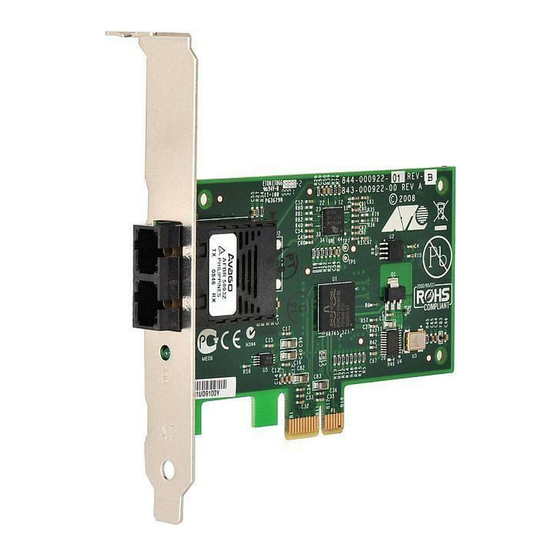
62.5/125 µm or 50/125 µm multimode specifications. This adapter operates at speeds of 100 Mbps in both full-duplex and half- duplex modes. The AT-2712FX/SC adapter has an SC connector, as show in Figure 1. 1478 Figure 1. AT-2712FX/SC Adapter... -
Page 17: At-2912T Adapter
AT-2712FX/SC and AT-2912T Secure Ethernet Network Adapter Installation and User’s Guide AT-2912T The AT-2912T adapter is a Gigabit Ethernet secure PCIe NIC featuring on-board encryption. It is fully compatible with other secure IPSec as well Adapter as non-IPSec NICs. This adapter operates at speeds of 10/100/1000T Mbps in both full-duplex and half-duplex modes. -
Page 18: Features
Chapter 1: Introducing the AT-2712FX/SC and AT-2912T Adapters Features The following list of features for the AT-2712FX/SC and AT-2912T adapters applies to all of the supported operating systems: PCI-Express x1 interface Flow Control (IEEE 802.1x) Layer 2 Priority Encoding (802.1p) ... -
Page 19: Physical Descriptions
See Adapter Physical Figure 3 for an illustration of the adapter’s faceplate. Description The AT-2712FX/SC adapter has one fiber port and one LED, as shown in Figure 3 and described in Table 1. 1484 Figure 3. AT-2712FX/SC Faceplate Table 1. - Page 20 Chapter 1: Introducing the AT-2712FX/SC and AT-2912T Adapters The AT-2912T adapter has one LED as described in Table 2. Table 2. Twisted-Pair Port LED Status State Description Green The port is operating at 10/100/1000 Mbps and has a valid link.
-
Page 21: Chapter 2: Installing The Hardware
Chapter 2 Installing the Hardware This chapter contains the following sections: “Reviewing Safety Precautions” on page 22 “Pre-Installation Checklist” on page 24 “Installing a Network Adapter Card” on page 27 “Connecting the Network Cables” on page 31 ... -
Page 22: Reviewing Safety Precautions
Note The indicates that a translation of the safety statement is available in a PDF document titled “Translated Safety Statements” on the Allied Telesis website at www.alliedtelesis.com. Warning This is a “Class 1 LED product”. 1 Warning Do not stare into the laser beam. - Page 23 AT-2712FX/SC and AT-2912T Secure Ethernet Network Adapter Installation and User’s Guide - Make sure to use only insulated or nonconducting tools. - Verify that the system is powered OFF and unplugged before accessing internal components. - Installation or removal of adapters must be performed in a static- free environment.
-
Page 24: Pre-Installation Checklist
Before you install an adapter card, check the following list: 1. Verify that your system is using the latest BIOS. Note If you acquired the adapter software from the Allied Telesis support website, enter the path to where the adapter driver files reside on your system. -
Page 25: Replacing The Bracket
AT-2712FX/SC and AT-2912T Secure Ethernet Network Adapter Installation and User’s Guide Replacing the Bracket The AT-2712FX/SC adapter is shipped with the low-profile bracket attached to the adapter. The AT-2912T adapter is shipped with the standard bracket attached to the adapter. Depending on your PC, you may need to replace the bracket attached to your adapter. -
Page 26: Figure 6. Fastening Screws Onto Standard Bracket
Chapter 2: Installing the Hardware 2. Align the tabs of the standard bracket with the holes on the adapter and fasten the screws onto the adapter. See Figure 6. 1480 Figure 6. Fastening Screws onto Standard Bracket... -
Page 27: Installing A Network Adapter Card
AT-2712FX/SC and AT-2912T Secure Ethernet Network Adapter Installation and User’s Guide Installing a Network Adapter Card The following instructions apply to installing both the AT-2712FX/SC and AT-2912T adapters in most systems. For details about performing these tasks on your particular system, refer to the manuals that were supplied with your system. -
Page 28: Figure 7. Removing The Pc Cover
Chapter 2: Installing the Hardware Figure 7. Removing the PC Cover 3. Select an empty, non-shared PCI slot and remove the faceplate. Keep the faceplate in a safe place. You may need it for future use. See Figure 8. Figure 8. Removing the Faceplate From PCI Slot Note If you cannot locate or do not know how to find an appropriate PCI slot, refer to the documentation that came with your system. -
Page 29: Figure 9. Inserting The Adapter With A High-Profile Bracket
AT-2712FX/SC and AT-2912T Secure Ethernet Network Adapter Installation and User’s Guide 4. Remove the network adapter card from the shipping package and store the packaging material in a safe location. Caution Wear a grounding device and observe electrostatic discharge precautions when installing the network adapter card in a system. -
Page 30: Figure 10. Securing The Adapter With A High-Profile Bracket
Chapter 2: Installing the Hardware Figure 10. Securing the Adapter with a High-profile Bracket 7. Replace the system’s cover and secure it with the screws removed in Step 2. 8. Disconnect any personal antistatic devices. 9. Power the system on. Once the system returns to proper operation, the adapter hardware is fully installed. -
Page 31: Connecting The Network Cables
Exposed ports may cause skin or eye damage 1. Connect one end of the cable to the adapter. 2. For the AT-2712FX/SC adapter, connect the other end of the cable to the appropriate Ethernet fiber optic port. For the AT-2912T adapter, connect the other end of the cable to another twisted pair port. - Page 32 Chapter 2: Installing the Hardware...
-
Page 33: Chapter 3: Enabling Vista Ipsec
Enabling Vista IPSec This chapter describes how to enable the Vista IPSec Operating System on the AT-2712FX/SC and AT-2912T adapters. The installation procedure is identical for the both the Vista 32-bit and 64-bit operating systems. This chapter contains the following sections: “Introduction”... -
Page 34: Introduction
Microsoft’s Technet website, www.technet.microsoft.com, offers several technical publications as well as online seminars that describe Vista’s advanced IPSec and Firewall features and their implementation. These topics are beyond the scope of this chapter. Instead, Allied Telesis recommends that you consult Technet for additional information. -
Page 35: Setting Vista's Next Generation Tcp/Ip Stack
AT-2712FX/SC and AT-2912T Secure Ethernet Network Adapter Installation and User’s Guide Setting Vista’s Next Generation TCP/IP Stack After you install an Allied Telesis AT-2712FX/SC or AT-2912T adapter in your PC, the system detects the new hardware automatically when the Windows Vista Operating system first boots up. You are prompted to install the driver software for that device shortly after you log in. -
Page 36: Figure 12. Found New Hardware - Ethernet Controller Page
Enabling Vista IPSec 3. From the Found New Hardware page, select Locate and install driver software (recommended). The Found New Hardware - Ethernet Controller page is displayed. See Figure 12. Figure 12. Found New Hardware - Ethernet Controller Page 4. From the Found New Hardware - Ethernet Controller page, select Yes, always search online (recommended). -
Page 37: Figure 13. Found New Hardware - Ethernet Controller Insert The Disc Page
AT-2712FX/SC and AT-2912T Secure Ethernet Network Adapter Installation and User’s Guide Figure 13. Found New Hardware - Ethernet Controller Insert the Disc Page 5. Click I don’t have the disc. Show me other options. Note The AT-2712FX/SC and AT-2912T adapters are not shipped with a The Found New Hardware - Ethernet Controller Windows Couldn’t... -
Page 38: Figure 14. Found New Hardware - Ethernet Controller Windows Couldn't Find Driver Page
Enabling Vista IPSec Figure 14. Found New Hardware - Ethernet Controller Windows Couldn’t Find Driver Page 6. Select Browse my computer for drive software (advanced). The following page is displayed: Figure 15. Found New Hardware - Ethernet Controller Browse for Driver Software Page... -
Page 39: Figure 16. Found New Hardware - Ethernet Controller Installing Driver Page
AT-2712FX/SC and AT-2912T Secure Ethernet Network Adapter Installation and User’s Guide 7. Click the Browse button. Figure 16 is displayed. Figure 16. Found New Hardware - Ethernet Controller Installing Driver Page... -
Page 40: Figure 17. Update Driver Software - Allied Telesis At-2712Fx 100Fx Fiber Page
Enabling Vista IPSec Then a confirmation page is displayed. Figure 17 shows the confirmation page for an AT-2712FX/SC adapter. The confirmation page for the AT- 2912 adapter is similar to this page. Figure 17. Update Driver Software - Allied Telesis AT-2712FX 100FX Fiber Page 8. -
Page 41: Figure 18. Control Panel Window
AT-2712FX/SC and AT-2912T Secure Ethernet Network Adapter Installation and User’s Guide From the Start menu, select Settings and then the Control Panel. See Figure 18. Figure 18. Control Panel Window 9. From the Control Panel, select Administrative Tools. The Administrative Tools window is displayed. See Figure 19 on page... -
Page 42: Figure 19. Administrative Tools Window
Enabling Vista IPSec Figure 19. Administrative Tools Window 10. From the Administrative Tools window, select Computer Management. See the Computer Management window in Figure 20. Figure 20. Computer Management Window... -
Page 43: Figure 21. Device Manager Window
AT-2712FX/SC and AT-2912T Secure Ethernet Network Adapter Installation and User’s Guide 11. From the Computer Management, select Device Manager in the left panel. The Device Manager window is displayed. See Figure 21. On the Device Manager page, either “Allied Telesis AT-2712FX Fiber”... -
Page 44: Uninstalling The Driver Software
The procedure in this section describes how to uninstall the driver software. Caution Before uninstalling the Allied Telesis device, be sure to capture all of the Advanced Property settings because the properties are lost during the uninstall process. -
Page 45: Chapter 4: Installing Windows Server 2003 And Windows Xp Driver Software
Installing Windows Server 2003 and Windows XP Driver Software This chapter describes how to install the Windows 2003 and Windows XP driver software in the AT-2712FX/SC and AT-2912T adapters. It contains the following sections: “Installing the Driver Software” on page 46 ... -
Page 46: Installing The Driver Software
Installing the Driver Software When a Windows Server 2003 or Windows XP system first boots up after you install a new Allied Telesis AT-2712FX/SC or AT-2912T adapter, the system automatically detects the new hardware and prompts you to install the driver software for that device. -
Page 47: Updating The Adapter Software
AT-2712FX/SC and AT-2912T Secure Ethernet Network Adapter Installation and User’s Guide Updating the This section provides a procedure for updating the adapter software for the Windows Server 2003 or Windows XP systems. Adapter Software Note You must have Administrator privileges to update the driver software. -
Page 48: Figure 22. System Properties Dialog Box
Installing Windows Server 2003 and Windows XP Driver Software The System Properties dialog box opens, as shown in Figure 22. Figure 22. System Properties Dialog Box 4. Select the Hardware Tab. The Hardware Tab is shown in Figure 23 on page 49. -
Page 49: Figure 23. Hardware Tab
AT-2712FX/SC and AT-2912T Secure Ethernet Network Adapter Installation and User’s Guide Figure 23. Hardware Tab 5. Click Device Manager. -
Page 50: Figure 24. Device Manager Window
Installing Windows Server 2003 and Windows XP Driver Software The Device Manager Window is shown in Figure 24. Figure 24. Device Manager Window 6. In the Device Manager window, click the + next to the Network Adapters folder. The selection expands to show the list of installed network adapter cards. -
Page 51: Figure 25. Welcome To Hardware Update Wizard Window
AT-2712FX/SC and AT-2912T Secure Ethernet Network Adapter Installation and User’s Guide 7. Right click on the adapter whose driver you want to update and select Update Driver. The Hardware Update Wizard Window opens, as shown in Figure 25. Figure 25. Welcome to Hardware Update Wizard Window 8. - Page 52 Installing Windows Server 2003 and Windows XP Driver Software 11. Click Next. 12. If you are prompted to specify the location of the drive, click Browse and locate the path of the drivers. Note Do not use the text field to locate the path of the drivers. After driver software installation is complete, you are ready to modify the configuration properties.
-
Page 53: Modifying Configuration Properties
AT-2712FX/SC and AT-2912T Secure Ethernet Network Adapter Installation and User’s Guide Modifying Configuration Properties Although the default values are appropriate in most cases, you can change any of the available options to meet the requirements of your system. After the adapter driver software has been installed, you can use this procedure to verify or change the following adapter properties: “802.1p QOS”... -
Page 54: Figure 27. Allied Telesis At-2712Fx 100 Mb Fiber Ethernet Properties Window
4. Click the “+” next to the Network Adapters folder. Then double click on the desired Allied Telesis network adapter. For the AT-2712FX/SC adapter, the Allied Telesis AT-2712FX 100 Mb Fiber Ethernet Properties window is displayed. See Figure 27. 5. Click the Advanced tab. -
Page 55: Checksum Offload
AT-2712FX/SC and AT-2912T Secure Ethernet Network Adapter Installation and User’s Guide Note Enabling 802.1p QOS also requires an 802.1p aware switch. 8. Click OK. 9. If prompted to restart your computer, click Yes. Although it is not necessary to reboot the system for new adapter properties to take effect, rebooting is recommended to reinitialize all registers. -
Page 56: Flow Control
3. In the “Hardware tab” on the System Properties dialog box, select “Device Manager.” The Device Manager window is shown in Figure 24 on page 50. 4. Click the “+” next to the Network Adapters folder. Then double click on the desired Allied Telesis network adapter. -
Page 57: Large Send Offload
AT-2712FX/SC and AT-2912T Secure Ethernet Network Adapter Installation and User’s Guide For the AT-2712FX/SC adapter, the Allied Telesis AT-2712FX 100 Mb Fiber Ethernet Properties window is displayed. See Figure 27 on page 5. From the Property list on the Advanced tab, select Flow Control. -
Page 58: Locally Administered Address
4. Click the “+” next to the Network Adapters folder. Then double click on the desired Allied Telesis network adapter. For the AT-2712FX/SC adapter, the Allied Telesis AT-2712FX 100 Mb Fiber Ethernet Properties window is displayed. See Figure 27 on page 5. -
Page 59: Speed And Duplex Mode
AT-2712FX/SC and AT-2912T Secure Ethernet Network Adapter Installation and User’s Guide The System Properties dialog box opens, as shown in Figure 22 on page 48. 3. In the “Hardware tab” on the System Properties dialog box, select “Device Manager.” The Device Manager window is shown in Figure 24 on page 50. - Page 60 100 Mb Half Auto For the AT-2712FX/SC adapter, you can only select either the 100 Mb Full or the 100 MB Half speeds and duplex modes. For the AT-2912T adapter, you can select from all 5 options. 8. Click OK.
-
Page 61: Wake Up Capabilities
AT-2712FX/SC and AT-2912T Secure Ethernet Network Adapter Installation and User’s Guide Wake Up The Wake Up Capabilities property enables the network adapter to wake up from a low-power mode when it receives a network wake-up frame. Capabilities There are two types of wake-up frames: Magic Packet and Wake Up Frame. -
Page 62: Wol Speed
4. Click the “+” next to the Network Adapters folder. Then double click on the desired Allied Telesis network adapter. For the AT-2712FX/SC adapter, the Allied Telesis AT-2712FX 100 Mb Fiber Ethernet Properties window is displayed. See Figure 27 on page 5. -
Page 63: Uninstalling The Driver Software
AT-2712FX/SC and AT-2912T Secure Ethernet Network Adapter Installation and User’s Guide Uninstalling the Driver Software Before physically removing an adapter from your system, first uninstall the adapter driver software. For instructions on how to uninstall the driver software, refer to the chapter in this manual that pertains to your platform. - Page 64 Installing Windows Server 2003 and Windows XP Driver Software 7. Click OK to complete the uninstall. Note Not all driver files are removed as part of this procedure. Note that drivers and adapters can be removed via the Hot Plug application, if it is supported.
-
Page 65: Chapter 5: Enabling Linux
Chapter 5 Enabling LINUX This chapter describes how to enable the LINUX System on the AT- 2712FX/SC and AT-2912T adapters. This chapter contains the following sections: “Introduction” on page 66 “Installing LINUX TG3 File” on page 67 “Unloading and Removing the Driver” on page 72 ... -
Page 66: Introduction
Enabling LINUX Introduction This chapter describes the tg3 Linux driver for the Broadcom NetXtreme PCI/PCI-X/PCI Express Ethernet Network Controllers. The most recent driver is in the latest 2.6 Linux kernel. You can download the driver from www.broadcom.com as a source package. However, it is generally not necessary to do so if you are using the latest 2.6 upstream kernel from www.kernel.org or one of the latest vendor kernels from Red Hat, SuSE, or others. -
Page 67: Installing Linux Tg3 File
AT-2712FX/SC and AT-2912T Secure Ethernet Network Adapter Installation and User’s Guide Installing LINUX TG3 File There are two procedures to install the Linux TG3 file: “Installing the Source RPM Package” on page 67 “Building the Driver from the Source TAR File” on page 68 ... -
Page 68: Building The Driver From The Source Tar File
Enabling LINUX Note The force option may be needed on some Linux distributions if conflicts are reported. Depending on the kernel, the driver is installed in one of the following directories: 2.4.x kernels: /lib/modules/<kernel_version>/kernel/drivers/net/ tg3.o 2.6.x kernels: /lib/modules/<kernel_version>/kernel/drivers/net/ tg3.ko 5. To load the driver, enter one of the following commands: insmod tg3.o insmod tg3.ko (on 2.6 kernels) modprobe tg3... -
Page 69: Driver Settings
AT-2712FX/SC and AT-2912T Secure Ethernet Network Adapter Installation and User’s Guide Enter the following command: make KVER=<kernel_version> where <kernel_version> in the form of 2.x.y-z is the version of another kernel that is installed on the system. 4. Test the driver by loading it. Enter the following commands: insmod tg3.o... -
Page 70: Driver Default Settings
Enabling LINUX Add the following line to the script: ETHTOOL_OPTS=”wol g speed 100 duplex half autoneg off” Table 3. Ethtool Utility Examples Action Commands Display current speed, duplex, and link ethtool eth0 status Change speed, duplex mode, and ethtool -s eth0 speed 100 autonegotiation status to 100Mbps duplex half autoneg off half duplex, and no autonegotiation... - Page 71 AT-2712FX/SC and AT-2912T Secure Ethernet Network Adapter Installation and User’s Guide Table 4. Linux Driver Settings (Continued) Feature Default Setting Coalesce Rx usecs 20 (range 0 - 1023) Coalesce Rx usecs irq 20 (range 0 - 255) Coalesce Rx frames...
-
Page 72: Unloading And Removing The Driver
Enabling LINUX Unloading and Removing the Driver To unload the driver, use the ifconfig command to bring down all eth# interfaces opened by the driver. Then enter the following command: rmmod tg3 Note On all 2.6 kernels, you do not need to bring down the eth# interfaces before unloading the driver module. -
Page 73: Driver Messages
AT-2712FX/SC and AT-2912T Secure Ethernet Network Adapter Installation and User’s Guide Driver Messages The following messages are the most common sample messages that are logged in the /var/log/messages file. Use the dmesg -n<level> command to control the level at which messages appear on the console. Most systems are set to level 6 by default. - Page 74 Enabling LINUX...
-
Page 75: Chapter 6: Ms-Dos Diagnostics
Chapter 6 MS-DOS Diagnostics This chapter describes the MS-DOS diagnostics and contains the following sections: “Introduction” on page 76 “DOS Prompt Commands” on page 77 “Diagnostic Tests” on page 78 “Error Messages” on page 85 ... -
Page 76: Introduction
Introduction This section provides the information on how to use the DOS diagnostic utilities program on an Allied Telesis Fast Ethernet adapter. For detailed information about the DOS diagnostic utilities program, see the Broadcom B57UDIAG Diagnostics Users Guide. You can download this document from the Allied Telesis website: www.alliedtelesis.com. -
Page 77: Dos Prompt Commands
AT-2712FX/SC and AT-2912T Secure Ethernet Network Adapter Installation and User’s Guide DOS Prompt Commands Table 6 lists the DOS prompt commands. Table 6. DOS Prompt Commands Command Description -c <num> Specify adapter to be tested and/or modified -cmd Enter command mode -w <value>... -
Page 78: Diagnostic Tests
MS-DOS Diagnostics Diagnostic Tests The tests are divided into four groups: Register Tests, Memory Tests, Miscellaneous Tests, and Data Tests. They numbered as group ‘A’, ‘B’, ‘C’, and ‘D’. Test Names This section lists the names of the diagnostics tests. Group A. -
Page 79: Test Descriptions
AT-2712FX/SC and AT-2912T Secure Ethernet Network Adapter Installation and User’s Guide Test Descriptions This section provides descriptions of the diagnostic tests. A1. Indirect Register Test Function: Using an indirect addressing method, writing increment data into MAC hash Register table and reading it back for verification. The memory read/write is done 100 times while increment test data. - Page 80 MS-DOS Diagnostics data is correct. After the test, the program reads back data one more time to insure the data stays correct. The test data used is 0x00000000, 0xFFFFFFFF, 0xAA55AA55, and 0x55AA55AA. Address Test: Writes each address with unique increment data. Read back data to insure data is correct.
- Page 81 AT-2712FX/SC and AT-2912T Secure Ethernet Network Adapter Installation and User’s Guide Table 7. DMA Test Patterns Test Pattern Description "16 00's 16 FF's" Full the entire host DMA buffer with 16 bytes of 00’s and then 16 bytes of FF’s.
- Page 82 MS-DOS Diagnostics C3. DMA Test Function: Both high and low priorities DMA are tested. It moves data from the host memory to NIC SRAM, verifies data, and then moves data back to the host memory again to verify data. Default: Enabled C4.
- Page 83 AT-2712FX/SC and AT-2912T Secure Ethernet Network Adapter Installation and User’s Guide C5. VPD Test Function: It saves the content of VPD before it performs the test. Once the test is done, this function writes one of the following five pattern test...
- Page 84 MS-DOS Diagnostics D1. Mac Loopback Test Function: This is internal loopback data transmit/receive test. It initializes the MAC into internal loopback mode and transmits 100 packets. The data should be routed back to the receive channel and received by the receive routine which verifies the integrity of data.
-
Page 85: Error Messages
AT-2712FX/SC and AT-2912T Secure Ethernet Network Adapter Installation and User’s Guide Error Messages /* 0 */ "PASS", /* 1 */ "Got 0x%08X @ 0x%08X. Expected 0x%08X", /* 2 */ "Cannot perform task while chip is running", /* 3 */ "Invalid NIC device", /* 4 */"Read only bit %s got changed after writing zero at... - Page 86 MS-DOS Diagnostics /* 24 */ "Cannot reset CPU", /* 25 */ "Cannot release CPU", /* 26 */ "CPU test failed", /* 27 */ "Invalid Test Address Range\nValid NIC address is 0x%08X-0x%08X and exclude 0x%08X-0x%08X", /* 28 */ "DMA:Got 0x%08X @ 0x%08X. Expected 0x%08X", /* 29 */ "Unsupported PhyId %04X:%04X", /* 30 */ "Too many registers specified in the file, max is %d",...
- Page 87 AT-2712FX/SC and AT-2912T Secure Ethernet Network Adapter Installation and User’s Guide /* 50 */ "Cannot perform task while chip is not running. (need driver)", /* 51 */ "Cannot open register define file or content is bad", /* 52 */ "ASF Reset bit did not self-cleared", /* 53 */ "ATTN_LOC %d cannot be mapped to %cX CPU event bit...
- Page 88 MS-DOS Diagnostics /* 73 */ "MII error bits set: %04x", /* 74 */ "CPU does not initialize MAC address register correctly", /* 75 */ "Invalid firmware file format", /* 76 */ "Resetting TX CPU Failed", /* 77 */ "Resetting RX CPU Failed", /* 78 */ "Invalid MAC address", /* 79 */ "Mac address registers are not initialized correctly",...
-
Page 89: Appendix A: Specifications
Physical Specifications This section provides the dimensions and weight of the adapters. Dimensions: AT-2712FX/SC: 11.59 cm x 6.89 cm (4.56 in. x 2.71 in.) AT-2912T: 8.18 cm x 6.89 cm (3.22 in. x 2.71 in.) Weight: AT-2712FX/SC: 45.36 g (.10 lbs.) AT-2912T: 45.36 g (.10 lbs.) -
Page 90: Performance Specifications
Appendix A: Specifications Performance Specifications The following performance specifications apply to both the AT-2712FX/SC and AT-2912T adapters: PCI clock: 33/66 MHz max PCI-X clock: 66 to 133 MHz PCI or PCI-X Data/Address: AT-2712FX/SC 32-bit Operating Specifications The following operating specifications apply to the AT-2712FX/SC... - Page 91 AT-2712FX/SC and AT-2912T Secure Ethernet Network Adapter Installation and User’s Guide Table 9 lists the RJ-45 pin signals when a twisted-pair port is operating in the MDI configuration. Table 9. MDI Pin Signals (10Base-T or 100Base-TX) Signal Table 10 lists the RJ-45 port pin signals when a twisted-pair port is operating in the MDI-X configuration.
-
Page 92: Console Port Pinouts
Appendix A: Specifications Console Port Pinouts Table 12 lists the pin signals on the RJ-45 style serial terminal port for the AT-2912T adapter. Table 12. Console Port Pinouts Signal Ground Transmit Data Receive Data No Connection Ground No Connection No Connection No Connection...
Need help?
Do you have a question about the AT-2712FX and is the answer not in the manual?
Questions and answers