Table of Contents
Advertisement
Quick Links
Download this manual
See also:
User Manual
Advertisement
Table of Contents
Troubleshooting

Related Manuals for Allied Telesis AT-2711FX


Summary of Contents for Allied Telesis AT-2711FX
- Page 1 Fast Ethernet Network Adapter AT-2711FX Installation and User’s Guide 613-000525 Rev. A...
- Page 2 Copyright © 2006 Allied Telesyn, Inc. All rights reserved. No part of this publication may be reproduced without prior written permission from Allied Telesyn, Inc. Microsoft and Internet Explorer are registered trademarks of Microsoft Corporation. Netscape Navigator is a registered trademark of Netscape Communications Corporation.
- Page 3 Electrical Safety and Emissions Standards This product meets the following standards. Federal Communications Commission Interference Statement Declaration of Conformity Manufacturer Name: Allied Telesyn, Inc. Declares that the product: Fast Ethernet Adapter Model Numbers: AT-2711FX This equipment has been tested and found to comply with the limits for a Class B digital device, pursuant to Part 15 of FCC Rules.
- Page 4 Translated Safety Statements Important: Appendix C contains translated safety statements for installing this equipment. When you see the , go to Appendix C for the translated safety statement in your language. Wichtig: Anhang C enthält übersetzte Sicherheitshinweise für die Installation dieses Geräts. Wenn sehen, schlagen Sie in Anhang C den übersetzten Sicherheitshinweis in Ihrer Sprache nach.
-
Page 5: Table Of Contents
Contents Preface ....................................13 Safety Symbols Used in this Document..........................14 Where to Find Web-based Guides ............................15 Contacting Allied Telesyn ..............................16 Online Support ................................16 Email and Telephone Support ............................16 Returning Products................................16 Sales or Corporate Information .............................16 Management Software Updates ............................16 Chapter 1: Introduction to the Fast Ethernet Network Adapter ..................17 Functional Description ................................18 Contents of Your Shipment ............................18 Features ....................................19... - Page 6 Contents Locally Administered Address ............................58 Speed & Duplex................................59 Wake Up Capabilities ..............................60 WOL Speed ...................................61 Updating the Driver Software..............................63 Removing the Driver Software ..............................64 Chapter 5: Installing the Linux Driver Software ......................67 Installing the Linux Driver Software ............................68 Building a Driver from a TAR File ..........................68 Removing the tg3 Driver............................68 Network Installation................................70 Removing the Linux Driver from a TAR Installation ......................71...
- Page 7 AT-2711FX Fast Ethernet Adapter Installation Guide Test Descriptions.................................117 Error Messages ..................................123 Chapter 11: Broadcom Advanced Control Suite 2 (BACS 2) Applications ..............127 Overview.....................................128 Information Provided by the BACS 2 Applications ......................129 Installing the BACS 2 Application ............................130 Installing and Using the GUI............................130 Using Silent Installation ...............................130 Managing the BACS Application ............................132 Initializing the BACS 2 Application ..........................132...
- Page 8 Contents...
- Page 9 Figures Figure 1. Adapter Faceplate ..............................20 Figure 2. Removing the PC Cover............................26 Figure 3. Removing the Faceplate From PCI Slot .......................27 Figure 4. Inserting the Network Adapter Card ........................28 Figure 5. Securing the Adapter Card ...........................29 Figure 6. Welcome to Found New Hardware Wizard Window.....................33 Figure 7.
- Page 10 Figures...
- Page 11 Tables Table 1. Safety Symbols ..............................14 Table 2. Fiber Optic Port 100 LED Status ..........................20 Table 3. 100BASE-FX Fiber Optic Cable Specifications ....................30 Table 4. NetWare Support Files ............................79 Table 5. Fiber Optic Port 100 LED Status ........................105 Table 6. Linux Driver Software Information ........................107 Table 7.
- Page 12 Tables...
-
Page 13: Preface
Preface This guide contains instructions on how to install the AT-2711FX Fast Ethernet adapter. In addition, procedures are provided that describe how to install and configure the software drivers. The Preface contains the following sections: “Safety Symbols Used in this Document” on page 14 “Where to Find Web-based Guides”... -
Page 14: Safety Symbols Used In This Document
Preface Safety Symbols Used in this Document This document uses the safety symbols defined in Table 1. Table 1. Safety Symbols Symbol Meaning Description Caution Performing or omitting a specific action may result in equipment damage or loss of data. Warning Performing or omitting a specific action may result in electrical shock. -
Page 15: Where To Find Web-Based Guides
Where to Find Web-based Guides The installation and user guides for all Allied Telesyn products are available in portable document format (PDF) on our web site at www.alliedtelesyn.com. You can view the documents online or download them onto a local workstation or server. -
Page 16: Contacting Allied Telesyn
To obtain an RMA number, contact Allied Telesyn Technical Support through our web site: www.alliedtelesyn.com. Sales or You can contact Allied Telesyn for sales or corporate information through our web site: www.alliedtelesyn.com. To find the contact information for Corporate your country, select Contact Us -> Worldwide Contacts. Information... -
Page 17: Chapter 1: Introduction To The Fast Ethernet Network Adapter
Chapter 1 Introduction to the Fast Ethernet Network Adapter This chapter provides an introduction to the Allied Telesyn AT-2711FX Fast Ethernet network adapter and contains the following sections: “Functional Description” on page 18 “Features” on page 19 “Physical Description” on page 20... -
Page 18: Functional Description
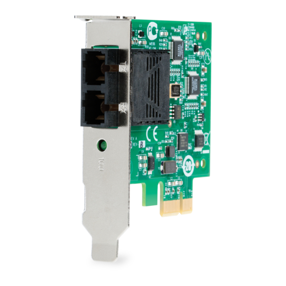
Introduction to the Fast Ethernet Network Adapter Functional Description The adapter connects a PCI-E compliant server or workstation to a Fast Ethernet network using fiber optic cabling and a connector that meets 62.5/125 µm or 50/125 µm multimode specifications. This adapter operates at 100 Mbps full-duplex and half-duplex mode. -
Page 19: Features
AT-2711FX Fast Ethernet Adapter Installation Guide Features Following is a list of the AT-2711FX Fast Ethernet network adapter features: PCI-Express x1 interface Flow Control (IEEE 802.1x) Layer 2 Priority Encoding (802.1p) TCP checksum RX/TX support 72 KB packet buffer PXE remote root support Wake on LAN (WOL) Available with SC, ST, or MT-RJ multimode fiber connectors... -
Page 20: Physical Description
Introduction to the Fast Ethernet Network Adapter Physical Description The faceplate on the AT-2711FX Fast Ethernet network adapter provides two fiber optic connectors for attaching the adapter to a compatible link partner. See Figure 1 for an illustration of the adapter’s faceplate. Figure 1. -
Page 21: Chapter 2: Installing The Hardware
Chapter 2 Installing the Hardware This chapter contains the following sections: “System Requirements” on page 22 “Reviewing Safety Precautions” on page 23 “Pre-Installation Checklist” on page 25 “Installing a Network Adapter Card” on page 26 “Connecting the Network Cables” on page 30... -
Page 22: System Requirements
Installing the Hardware System Requirements Before installing the AT-2711FX Fast Ethernet network adapter, make sure your system meets the requirements listed for your operating system. Windows The following lists the requirements for the Windows 2000, Windows XP SP2, and Windows Server 2003 systems: Requirements Pentium-based computer that meets Windows 2000, Windows XP SP2, or Windows Server 2003 software requirements... -
Page 23: Reviewing Safety Precautions
AT-2711FX Fast Ethernet Adapter Installation Guide Reviewing Safety Precautions Please review the following safety precautions before you begin to install the network adapter card. Refer to Appendix C, “Translated Safety Statements” on page 155 for translated safety statements in your language. - Page 24 Installing the Hardware - Installation or removal of adapters must be performed in a static- free environment. The use of a properly grounded wrist strap or other personal antistatic devices and an antistatic mat is strongly recommended.
-
Page 25: Pre-Installation Checklist
AT-2711FX Fast Ethernet Adapter Installation Guide Pre-Installation Checklist 1. Check that your server meets the hardware and software requirements listed under “System Requirements” on page 22. 2. Verify that your system is using the latest BIOS. 3. Review the information in the readme.txt file on the CD-ROM for important information not available at the time this manual was created. -
Page 26: Installing A Network Adapter Card
Installing the Hardware Installing a Network Adapter Card The following instructions apply to installing the Fast Ethernet adapter in most systems. Refer to the manuals that were supplied with your system for details about performing these tasks on your particular system. To install the network adapter card, perform the following procedure: 1. -
Page 27: Figure 3. Removing The Faceplate From Pci Slot
AT-2711FX Fast Ethernet Adapter Installation Guide 3. Select an empty, non-shared PCI-E slot and remove the faceplate. Keep the faceplate in a safe place. You may need it for future use. See Figure 3. Figure 3. Removing the Faceplate From PCI Slot Note If you cannot locate or know how to find an PCI-E slot, refer to the documentation that came with your system. -
Page 28: Figure 4. Inserting The Network Adapter Card
Installing the Hardware Make sure the card is securely seated. See Figure 4. Figure 4. Inserting the Network Adapter Card Caution Do not use excessive force when seating the card, as this may damage the system or the adapter. If the card resists seating, remove it from the system, realign it, and try again. -
Page 29: Figure 5. Securing The Adapter Card
AT-2711FX Fast Ethernet Adapter Installation Guide 6. Secure the network adapter card to the chassis with a Phillips-head screw (not provided) as shown in Figure 5. Figure 5. Securing the Adapter Card 7. Replace the system’s cover and secure it with the screws removed in Step 2. -
Page 30: Connecting The Network Cables
Installing the Hardware Connecting the Network Cables To connect a network cable to the adapter, perform the following procedure: 1. Prepare a fiber optic cable according to the specifications in Table 2. Table 2. 100BASE-FX Fiber Optic Cable Specifications Maximum Port Type Connector Media... -
Page 31: Chapter 3: Installing Windows Server 2003 And Windows Xp Driver Software
Chapter 3 Installing Windows Server 2003 and Windows XP Driver Software This chapter describes how to install the Windows 2003 and Windows XP driver software. It contains the following sections: “Installing the Driver Software” on page 32 “Modifying Configuration Properties” on page 41 “Uninstalling the Driver Software”... -
Page 32: Installing The Driver Software
Installing Windows Server 2003 and Windows XP Driver Software Installing the Driver Software When a Windows Server 2003 or Windows XP system first boots up after you install a new Allied Telesyn AT-2711FX Fast Ethernet network adapter, the system automatically detects the new hardware and prompts you to install the driver software for that device. -
Page 33: Figure 6. Welcome To Found New Hardware Wizard Window
AT-2711FX Fast Ethernet Adapter Installation Guide Note If you have a Windows XP system, the window in Figure 6 opens. Start with step 1. If you have a Windows Server 2003 system, the window in Figure 7 on page 34 opens. Start with step 2 on the same page. -
Page 34: Figure 7. Found New Hardware Wizard Window
Installing Windows Server 2003 and Windows XP Driver Software The second Welcome to Found New Hardware Wizard Window is shown in Figure 7. Figure 7. Found New Hardware Wizard Window 6. Insert the CD-ROM or floppy diskette. 7. Click Install the Software Automatically (Recommended). 8. -
Page 35: Updating The Adapter Software
AT-2711FX Fast Ethernet Adapter Installation Guide Updating the This section provides a procedure for updating the adapter software for the Windows Server 2003 or Windows XP systems. Adapter Software Note You may need to reboot your system after completing the driver update to properly load the new drivers. -
Page 36: Figure 8. System Properties Dialog Box
Installing Windows Server 2003 and Windows XP Driver Software The System Properties dialog box opens, as shown in Figure 8. Figure 8. System Properties Dialog Box 4. Select the Hardware Tab. The Hardware Tab is shown in Figure 9 on page 37. -
Page 37: Figure 9. Hardware Tab
AT-2711FX Fast Ethernet Adapter Installation Guide Figure 9. Hardware Tab 5. Click Device Manager. -
Page 38: Figure 10. Device Manager Window
Installing Windows Server 2003 and Windows XP Driver Software The Device Manager Window is shown in Figure 10. Figure 10. Device Manager Window 6. Insert the CD-ROM. 7. In the Device Manager window, click the + next to the Network Adapters folder. -
Page 39: Figure 11. Welcome To Hardware Update Wizard Window
AT-2711FX Fast Ethernet Adapter Installation Guide The Hardware Update Wizard Window opens, as shown in Figure 11. Figure 11. Welcome to Hardware Update Wizard Window 9. For a Windows 2003 system, skip to step 10. For a Windows XP system, click No, not this time to copy the driver software from the CD-ROM. - Page 40 Installing Windows Server 2003 and Windows XP Driver Software After driver software installation is complete, you are ready to modify the configuration properties. See “Modifying Configuration Properties” on page 41.
-
Page 41: Modifying Configuration Properties
AT-2711FX Fast Ethernet Adapter Installation Guide Modifying Configuration Properties Although the default values should be appropriate in most cases, you can change any of the available options to meet the requirements of your specific system. After the adapter driver software has been installed, you can use this procedure to verify or change the following adapter properties: “802.1p QOS”... -
Page 42: Figure 13. Advanced Tab
Installing Windows Server 2003 and Windows XP Driver Software The System Properties dialog box opens, as shown in Figure 8 on page 36. 4. Click the Advanced tab. The Advanced tab is shown in Figure 13. Figure 13. Advanced Tab 5. -
Page 43: Checksum Offload
AT-2711FX Fast Ethernet Adapter Installation Guide 9. Verify that the adapter port LEDs operate as described in “Physical Description” on page 20. Checksum Usually, the Checksum Offload function is computed by the protocol stack. By selecting one of the Checksum Offload properties, the adapter can Offload compute the checksum. -
Page 44: Ethernet Wire Speed
Installing Windows Server 2003 and Windows XP Driver Software Ethernet Wire This feature is not supported on the AT-2711FX Fast Ethernet network adapter. Speed Flow Control The Flow Control property allows you to enable or disable the receipt or transmission of PAUSE frames which enable the adapter and the switch to control the transmit rate. -
Page 45: Large Send Offload
AT-2711FX Fast Ethernet Adapter Installation Guide Even though it is not necessary to reboot the system for new adapter properties to take effect, rebooting is recommended to reinitialize all registers. 9. Verify that the adapter port LEDs operate as described in “Physical Description”... -
Page 46: Locally Administered Address
Installing Windows Server 2003 and Windows XP Driver Software Locally The Locally Administered Address is a user-defined address that is used in place of the MAC address originally assigned to the adapter. Every Administered adapter in the network must have its own unique MAC address. This Address locally administered address consists of a 12-digit hexadecimal number. -
Page 47: Wol Speed
AT-2711FX Fast Ethernet Adapter Installation Guide To change the Wake Up Capabilities property, perform the following procedure: 1. Start either a Windows Server 2003 system or a Windows XP system and log in. You must have Administrator privileges to update the driver software. 2. - Page 48 Installing Windows Server 2003 and Windows XP Driver Software 4. Click the Advanced tab. The Advanced tab is shown in Figure 13 on page 42. 5. From the Properties list, select Wake Up Capabilities. 6. From the Values list, select one of the following: 100Mb - Sets the speed to 100 Mb.
-
Page 49: Uninstalling The Driver Software
AT-2711FX Fast Ethernet Adapter Installation Guide Uninstalling the Driver Software Before physically removing an adapter from your system, first uninstall the adapter driver software. For instructions on how to uninstall the driver software, see the chapter that pertains to your platform. Caution Before uninstalling the Allied Telesyn device, be sure to capture all Advanced Property settings because the properties are lost during... - Page 50 Installing Windows Server 2003 and Windows XP Driver Software 7. Click OK to complete the uninstall. Note Not all driver files are removed as part of this procedure. Note that drivers and adapters can be removed via the Hot Plug application, if it is supported.
-
Page 51: Chapter 4: Installing Windows 2000 Driver Software
Chapter 4 Installing Windows 2000 Driver Software This chapter provides procedures for installing the Windows 2000 Driver software and contains the following sections: “Installing the Windows 2000 Driver Software” on page 52 “Modifying Configuration Properties” on page 54 “Updating the Driver Software” on page 63 “Removing the Driver Software”... -
Page 52: Installing The Windows 2000 Driver Software
Installing Windows 2000 Driver Software Installing the Windows 2000 Driver Software Note The Allied Telesyn adapter must be physically installed in your system before installing the driver software. See Chapter 2, “Installing the Hardware” on page 21 for details. When the Windows 2000 system first boots up after installing a new hardware device, such as an Allied Telesyn adapter, the system automatically detects the new hardware and prompts you to install the driver software for that device. - Page 53 AT-2711FX Fast Ethernet Adapter Installation Guide 3. In the Locate Driver Files window, select the applicable search location check boxes, then click Next. 4. When prompted, insert the media to be searched into your CD-ROM drive, type the path to the driver, and select OK. For example, where "e"...
-
Page 54: Modifying Configuration Properties
Installing Windows 2000 Driver Software Modifying Configuration Properties Although the default values should be appropriate in most cases, you can change any of the available options to meet the requirements of your specific system. After the adapter driver software has been installed, you can use this procedure to verify or change the following adapter properties: “802.1p QOS”... -
Page 55: 802.1P Qos
AT-2711FX Fast Ethernet Adapter Installation Guide Figure 14. Advanced Tab 4. Change the operating properties as needed. To change adapter operating property, click a property in the Property list and then select a setting from Value list. See the following sections for a description of the properties. -
Page 56: Checksum Offload
Installing Windows 2000 Driver Software The System Properties dialog box opens, as shown in Figure 8 on page 36. 4. Click the Advanced tab. The Advanced tab is shown in Figure 13 on page 42. 5. From the Properties list, select 802.1p QOS. 6. -
Page 57: Ethernet Wire Speed
AT-2711FX Fast Ethernet Adapter Installation Guide The Advanced tab is shown in Figure 13 on page 42. 5. From the Properties list, select Checksum Offload. 6. From the Values list, select one of the following: None - Disables checksum offloading. Rx TCP/IP Checksum - Enables receive TCP, IP, and UDP checksum offloading. -
Page 58: Locally Administered Address
Installing Windows 2000 Driver Software The System Properties dialog box opens, as shown in Figure 8 on page 36. 4. Click the Advanced tab. The Advanced tab is shown in Figure 13 on page 42. 5. From the Properties list, select Flow Control. 6. -
Page 59: Speed & Duplex
AT-2711FX Fast Ethernet Adapter Installation Guide The System Properties dialog box opens, as shown in Figure 8 on page 36. 4. Click the Advanced tab. The Advanced tab is shown in Figure 13 on page 42. 5. From the Properties list, select Locally Administered Address. 6. -
Page 60: Wake Up Capabilities
Installing Windows 2000 Driver Software 5. From the Properties list, select Speed & Duplex. 6. From the Values list, select one of the following: 100 Mb Full. Sets the speed at 100 Mbit/s and the mode to Full- Duplex. 100 Mb Half. Sets the speed at 100 Mbit/s and the mode to Half- Duplex. -
Page 61: Wol Speed
AT-2711FX Fast Ethernet Adapter Installation Guide 5. From the Properties list, select Wake Up Capabilties. 6. From the Values list, select one of the following: Both (default). Selects both Magic Packet and Wake Up Frame as wake-up frames. Magic Packet. Selects Magic Packet as the wake-up frame. None. - Page 62 Installing Windows 2000 Driver Software 100 Mb. Sets the speed to 100 Mbit/s. Auto (default). Sets the speed for optimum network connection. 7. Click OK. 8. If prompted to restart your computer, click Yes. Even though it is not necessary to reboot the system for new adapter properties to take effect, rebooting is recommended to reinitialize all registers.
-
Page 63: Updating The Driver Software
AT-2711FX Fast Ethernet Adapter Installation Guide Updating the Driver Software To replace adapter driver software with newer versions as they become available, perform the following procedure: 1. Start Windows 2000 and log in. Note You must have Administrator privileges to remove the driver software. -
Page 64: Removing The Driver Software
Installing Windows 2000 Driver Software Removing the Driver Software To remove the network adapter driver software, perform the following procedure: Caution Before uninstalling the Allied Telesyn device, be sure to capture all Advanced Property settings because the properties are lost during the uninstall process. - Page 65 AT-2711FX Fast Ethernet Adapter Installation Guide Note Not all driver files are removed as part of this procedure. Note that the driver and adapter can be removed via the Hot Plug application, if it is supported.
- Page 66 Installing Windows 2000 Driver Software...
-
Page 67: Chapter 5: Installing The Linux Driver Software
Chapter 5 Installing the Linux Driver Software This chapter describes the Linux driver for the AT-2711FX Fast Ethernet adapter and includes the following sections: “Installing the Linux Driver Software” on page 68 “Network Installation” on page 70 “Removing the Linux Driver from a TAR Installation” on page 71 “Module Parameters”... -
Page 68: Installing The Linux Driver Software
Installing the Linux Driver Software Installing the Linux Driver Software The section describes the following Linux driver installations: “Building a Driver from a TAR File” on page 68 “Removing the tg3 Driver” on page 68 Note On some newer Distributions and Kernels, it may be necessary to remove the tg3 driver before loading the tg3 driver supplied on the CD. - Page 69 AT-2711FX Fast Ethernet Adapter Installation Guide that you use the newer tg3 driver provided by Allied Telesyn. Use ifconfig to bring down all eth# interfaces used by tg3 and enter the following command to unload the tg3 driver. rmmod tg3 For more detailed Linux specific information on ifconfig, rmmod, or modules.conf, refer to the respective man pages.
-
Page 70: Network Installation
Installing the Linux Driver Software Network Installation For network installations through NFS, FTP, or HTTP (using a network boot disk or PXE), a driver diskette that contains the tg3 driver may be needed. The driver diskette images for the most recent Red Hat versions are included. -
Page 71: Removing The Linux Driver From A Tar Installation
AT-2711FX Fast Ethernet Adapter Installation Guide Removing the Linux Driver from a TAR Installation If the driver was installed using make install from the tar file, you must manually delete the tg3.o driver. -
Page 72: Module Parameters
Installing the Linux Driver Software Module Parameters Optional parameters for the driver can be supplied as command line arguments to the insmod command. Typically, these parameters are set in the file /etc/modules.conf (see the man page for modules.conf). These parameters take the following form: <parameter>... - Page 73 AT-2711FX Fast Ethernet Adapter Installation Guide Note This parameter is ignored and assumed to be 1 if the line_speed parameter is set to 0. full_duplex Selects the duplexity of the link. This parameter is used together with line_speed to select the speed and duplexity of the link. Note that this parameter is ignored if line_speed is 0.
- Page 74 Installing the Linux Driver Software Enables jumbo frames up to the specified MTU size. The valid range for this parameter is 1500 to 9000. The default is 1500 which is the standard Ethernet (non-jumbo) MTU size. Note that the MTU size excludes the Ethernet header size of 14 bytes.
- Page 75 AT-2711FX Fast Ethernet Adapter Installation Guide rx_jumbo_desc_cnt Configures the number of receive descriptors for jumbo frames larger than 1528 bytes. The default is 128 and the valid range is from 1 to 255. When jumbo frames larger than 1528 bytes are used, this parameter should not be set lower than 60 on systems with high network traffic.
- Page 76 Installing the Linux Driver Software tx_coalesce_ticks Configures the number of 1 usec ticks before the NIC generates transmit interrupt after transmitting a frame. This parameter works in conjunction with the tx_max_coalesce_frames parameter. Interrupt is generated when either of these thresholds is exceeded. A value of 0 means this parameter is ignored and an interrupt is generated when the tx_max_coalesce_frames threshold is reached.
-
Page 77: Chapter 6: Installing The Netware Driver Software
Chapter 6 Installing the NetWare Driver Software This chapter provides procedures for installing the NetWare Driver software and contains the following sections: “Driver Installation” on page 78 “Pre-Installation Requirements” on page 79 “Installing Novell NetWare Server 5.x or 6.0 Driver Software” on page 80 “Verifying or Modifying Adapter Parameters”... -
Page 78: Driver Installation
Installing the NetWare Driver Software Driver Installation This chapter describes how to perform the following tasks: Verify that the required OS support files are installed on the server and the NetWare pre-installation parameters are set correctly. Install the driver software in the Novell NetWare environment. If necessary, reconfigure the driver software after installation. -
Page 79: Pre-Installation Requirements
AT-2711FX Fast Ethernet Adapter Installation Guide Pre-Installation Requirements A network device driver must be installed before the Fast Ethernet adapter can be used with your Novell NetWare system. Before you can successfully install the adapter driver for Novell NetWare, the adapter card must be physically installed in the server and, typically, the NetWare OS software must already be running on the server. -
Page 80: Installing Novell Netware Server 5.X Or 6.0 Driver Software
Installing the NetWare Driver Software Installing Novell NetWare Server 5.x or 6.0 Driver Software Ensure that the server has the latest support pack available installed. The latest support packs can be found at: http://support.novell.com/misc/ patlst.htm. You may want to create an archive disk by copying all the files from the CDROM\Driver\Netware directory onto a floppy disk. - Page 81 AT-2711FX Fast Ethernet Adapter Installation Guide 12. Select Save parameters and load driver to continue. 13. Choose Exit to return to the server console prompt. Note If you are performing an initial installation of NetWare 5.x or 6.0 and have more than two adapters installed, the install program allows you to allocate the actual number of packet receive buffers needed by the adapter.
-
Page 82: Verifying Or Modifying Adapter Parameters
Installing the NetWare Driver Software Verifying or Modifying Adapter Parameters When an adapter configuration is saved, the NetWare install program adds load and bind statements to the autoexec.ncf file. By accessing this file, you can verify the parameters configured for each adapter, modify them, or enter additional parameters. - Page 83 AT-2711FX Fast Ethernet Adapter Installation Guide TxPacketsPer= This is to enable the use of allowing an interrupt to occur after a specific amount of packets are transmitted. Min = 0, disabled Max = 100 Default is 20 RxPacketsPer= This is to enable the use of allowing an interrupt to occur after a specific amount of packets are received.
- Page 84 Installing the NetWare Driver Software FRAME= This is a Novell NetWare keyword. String specifying the frame type. Choices are: ETHERNET_II ETHERNET_802.3 ETHERNET_802.2 ETHERNET_SNAP Default value is ETHERNET_802.2 SLOT= This is a Novell NetWare keyword. System-wide unique Hardware Instance Number (HIN) that may be the physical slot number on a slot based bus such as PCI.
- Page 85 AT-2711FX Fast Ethernet Adapter Installation Guide The Default is spurious fix = 1 (spurious fix is on). Choices are: Spuriousfix=0 Spuriousfix=1 (default). Poll= To disable interrupt driven mode in the driver set Poll=1 and the driver will not use interrupts, but will be polled by the NetWare OS.
- Page 86 Installing the NetWare Driver Software Note If you modify any adapter parameters, you must reboot the system before the changes take effect. If you make changes and do not reboot, you may experience configuration problems. A valid autoexec.ncf file is shown below. One set of load and bind commands (in bold) is added for each frame type the adapter is configured to support.
-
Page 87: Removing Drivers From Autoexec.ncf
AT-2711FX Fast Ethernet Adapter Installation Guide Removing Drivers from Autoexec.ncf To remove the drivers from the Autoexec.ncf, locate the Load and Bind command lines associated with the Broadcom driver and remark them out by inserting the # symbol at the beginning of each command line, or by deleting the statement. - Page 88 Installing the NetWare Driver Software...
-
Page 89: Chapter 7: Installing The Boot Agent Driver Software
Chapter 7 Installing the Boot Agent Driver Software This chapter provides procedures for installing the Allied Telesyn Boot Agent Driver Software. It contains the following sections: “Overview” on page 90 “Server Setup” on page 92... -
Page 90: Overview
Installing the Boot Agent Driver Software Overview The Allied Telesyn Fast Ethernet adapter provides PXE (Preboot Execution Environment) and RPL (Remote Program Load) support. Multi- Boot Agent (MBA) is a software module that allows your networked computer to boot with the images provided by remote servers across the network. -
Page 91: Setup Bios
AT-2711FX Fast Ethernet Adapter Installation Guide Setup BIOS To boot from the network with MBA, make MBA the first bootable device under BIOS. This procedure depends on server BIOS implementation. Please refer to the server's user manual. -
Page 92: Server Setup
Installing the Boot Agent Driver Software Server Setup This section discusses how to set up a server on a Windows 2000, Windows Server 2003, Windows XP, DOS UNDI/APITEST, and Red Hat Linux systems. Windows 2000 The current version of Windows 2000 does not include a network driver for the Allied Telesyn Fast Ethernet adapters. - Page 93 AT-2711FX Fast Ethernet Adapter Installation Guide In this version, it prompts you to insert a driver disk for drivers that are not part of the standard distribution. You can create a driver disk for the adapter from the image distributed with the Allied Telesyn CD-ROM. A remote boot does not require a standard Linux network driver for the adapter.
- Page 94 Installing the Boot Agent Driver Software...
-
Page 95: Chapter 8: Installing The Ndis2 Driver Software
Chapter 8 Installing the NDIS2 Driver Software This chapter provides procedures for installing the NDIS2 Driver software. and contains the following sections: “Installing the NDIS2 Driver Software for Use on MS-DOS Platforms” on page 96 “Using Keywords for the B57.dos Drivers” on page 101... -
Page 96: Installing The Ndis2 Driver Software For Use On Ms-Dos Platforms
Installing the NDIS2 Driver Software Installing the NDIS2 Driver Software for Use on MS-DOS Platforms You can run the NDIS2 driver software from an MS-DOS startup disk using Microsoft Network Client 3.0. Pre-Installation Before you can successfully install the NDIS2 driver software, the Allied Telesyn Fast Ethernet adapter must be physically installed in the Requirements computer. - Page 97 AT-2711FX Fast Ethernet Adapter Installation Guide BINDINGS=MS$NE2CLONE LANABASE=0 Example Protocol.ini for IPX [network.setup] version=0x3110 netcard=ms$ne2clone,1,MS$NE2CLONE,1 transport=ms$ndishlp,MS$NDISHLP transport=ms$nwlink,MS$NWLINK lana0=ms$ne2clone,1,ms$nwlink lana1=ms$ne2clone,1,ms$ndishlp [MS$NE2CLONE] DriverName=B57$ [protman] DriverName=PROTMAN$ PRIORITY=MS$NDISHLP [MS$NDISHLP] DriverName=ndishlp$ BINDINGS=ms$ne2clone [ms$nwlink] DriverName=nwlink$ FRAME=Ethernet_802.2 BINDINGS=MS$NE2CLONE LANABASE=0 Example Protocol.ini for NetBEUI [network.setup] version=0x3110 netcard=ms$ne2clone,1,MS$NE2CLONE,1 transport=ms$ndishlp,MS$NDISHLP transport=ms$netbeui,MS$NETBEUI...
- Page 98 Installing the NDIS2 Driver Software lana0=ms$ne2clone,1,ms$ndishlp lana1=ms$ne2clone,1,ms$netbeui [MS$NE2CLONE] DriverName=B57$ [protman] DriverName=PROTMAN$ PRIORITY=MS$NDISHLP [MS$NDISHLP] DriverName=ndishlp$ BINDINGS=MS$NE2CLONE [MS$NETBEUI] DriverName=netbeui$ SESSIONS=10 NCBS=12 BINDINGS=MS$NE2CLONE LANABASE=0 2. Edit A:\Net\System.ini. a. Change netcard= to netcard=b57.dos. b. Check for references to C:\NET and change C:\NET to A:\NET if necessary.
- Page 99 AT-2711FX Fast Ethernet Adapter Installation Guide reconnect=yes dospophotkey=N lmlogon=0 logondomain= preferredredir=basic autostart=basic maxconnections=8 [network drivers] netcard=B57.dos transport=ndishlp.sys,*netbeui devdir=A:\NET LoadRMDrivers=yes 3. Copy B57.dos to A:\Net. 4. Create the appropriate Autoexec.bat file in drive A for the chosen protocol as shown below. For TCP/IP path=a:\net a:\net\net initialize...
- Page 100 Installing the NDIS2 Driver Software A:\NET\NET START BASIC net use z: \\SERVERNAME\SHARENAME For NetBEUI SET PATH=A:\NET A:\NET\NET START BASIC net use z: \\SERVERNAME\SHARENAME 5. Create a Config.sys file on the startup disk in drive A as shown below. files=30 device=a:\net\ifshlp.syslastdrive=z...
-
Page 101: Using Keywords For The B57.Dos Drivers
AT-2711FX Fast Ethernet Adapter Installation Guide Using Keywords for the B57.dos Drivers The Protocol.ini file contains certain keywords that are used by the B57.dos drivers. These keywords are listed below: BusNum. Specifies the PCI bus number on which the network controller is located. - Page 102 Installing the NDIS2 Driver Software...
-
Page 103: Chapter 9: Troubleshooting
Chapter 9 Troubleshooting This chapter describes troubleshooting procedures. It contains the following sections: “Hardware Diagnostics” on page 104 “Checking the Port LED on the Adapter” on page 105 “Troubleshooting Checklist” on page 106 “Verifying the Correct Drivers are Loaded” on page 107 “Testing Network Connectivity”... -
Page 104: Hardware Diagnostics
Troubleshooting Hardware Diagnostics DOS and Windows diagnostic tests are available for testing the adapter hardware under Windows. These tests provide access to the adapter's internal or external diagnostics, where packet information is transmitted across the physical link. Refer to Chapter 10, “DOS Diagnostics” on page 113 or Chapter 11, “Broadcom Advanced Control Suite 2 (BACS 2) Applications”... -
Page 105: Checking The Port Led On The Adapter
AT-2711FX Fast Ethernet Adapter Installation Guide Checking the Port LED on the Adapter The AT-2711FX Fast Ethernet adapter has one LED: 100. Before the port LED can provide troubleshooting information, the adapter must be connected to the network (see Chapter 2, “Installing the Hardware”... -
Page 106: Troubleshooting Checklist
Troubleshooting Troubleshooting Checklist The following checklist provides recommended actions to take to resolve problems installing the AT-2711FX Fast Ethernet adapter or running it in your system. Warning Before opening the cabinet of your system for removing or inserting the adapter, please review all precautions outlined under “Reviewing Safety Precautions”... -
Page 107: Verifying The Correct Drivers Are Loaded
AT-2711FX Fast Ethernet Adapter Installation Guide Verifying the Correct Drivers are Loaded The following section describes how to check if the correct drivers are loaded for NetWare and Linux. NetWare To verify that the NetWare Driver software is loaded correctly, perform the following procedure. -
Page 108: Testing Network Connectivity
Troubleshooting Testing Network Connectivity The following section describes how to test network connectivity for Windows 2000, Windows Server 2003, NetWare, and Linux networks. Note When using forced link speeds, make sure that both the adapter and the switch are forced to the same speed. Or, make sure at least one link partner is configured for Auto-Negotiation. -
Page 109: Netware
AT-2711FX Fast Ethernet Adapter Installation Guide Figure 16. Command Window with pconfig/all displayed 4. Type ping <IP address> from the command line, then press Enter. The network connectivity information is displayed, as shown in Figure 17. Figure 17. Command Window with ping displayed NetWare To ping an IP host on the network to verify a connection has been established, perform the following procedure. -
Page 110: Linux
Troubleshooting Linux To verify that the Ethernet interface is up and running, run 'ifconfig' to check the status of the Ethernet interface. In addition, you can also use the 'netstat -i' command to check the statistics on the Ethernet interface. Consult the manual pages for more information about the 'ifconfig' and 'netstat' commands. -
Page 111: Software Problems And Solutions
AT-2711FX Fast Ethernet Adapter Installation Guide Software Problems and Solutions Microsoft Remote Problem: Microsoft Remote Installation Service (RIS) installation fails for both Windows 2000 and Windows XP. Installation Service (RIS) Solution: Refer to Microsoft Article Q246184, "How to Add Third-Party Instructions OEM Network Adapters to RIS Installations."... - Page 112 Troubleshooting make clean make make install Problem: Zero copy performance is low on Red Hat 7.1. Solution: Red Hat 7.1 loads the ipchains module by default. IPCHAINS is not compatible with Zero Copy. Remove the IPCHAINS module and disable IPCHAINS from the system run level. Example: rmmod ipchains chkconfig ipchains off...
-
Page 113: Chapter 10: Dos Diagnostics
Chapter 10 DOS Diagnostics This chapter describes the DOS diagnostics and contains the following sections: “Introduction” on page 114 “DOS Prompt Commands” on page 115 “Diagnostic Tests” on page 116 “Error Messages” on page 123... -
Page 114: Introduction
DOS Diagnostics Introduction This section provides the information on how to use the DOS diagnostic utilities program on an Allied Telesyn Fast Ethernet adapter. Commands can be entered from the DOS prompt or the Command Line Interface (CLI), prompt. Otherwise, the parameter is used as an executable command then exits the program. -
Page 115: Dos Prompt Commands
AT-2711FX Fast Ethernet Adapter Installation Guide DOS Prompt Commands Table 7 lists the DOS prompt commands. Table 7. DOS Prompt Commands Command Description -c <num> Specify adapter to be tested and/or modified -cmd Enter command mode -w <value> Enable/Disable (value = 1/0) WOL in manufacture mode -mba <value>... -
Page 116: Diagnostic Tests
DOS Diagnostics Diagnostic Tests The tests are divided into four groups: Register Tests, Memory Tests, Miscellaneous Tests, and Data Tests. They numbered as group ‘A’, ‘B’, ‘C’, and ‘D’. Test Names This section lists the names of the diagnostics tests. Group A. -
Page 117: Test Descriptions
AT-2711FX Fast Ethernet Adapter Installation Guide Test Descriptions This section provides descriptions of the diagnostic tests. A1. Indirect Register Test Function: Using indirect addressing method, writing increment data into MAC hash Register table and read back for verification. The memory read/ write is done 100 times while increment test data. - Page 118 DOS Diagnostics data is correct. After the test, the program reads back data one more time to insure the data stays correct. The test data used is 0x00000000, 0xFFFFFFFF, 0xAA55AA55, and 0x55AA55AA. Address Test: Writes each address with unique increment data. Read back data to insure data is correct.
- Page 119 AT-2711FX Fast Ethernet Adapter Installation Guide Table 8. DMA Test Patterns Test Pattern Description "16 00's 16 FF's" Full the entire host DMA buffer with 16 bytes of 00’s and then 16 bytes of FF’s. "16 FF's 16 0's" Full the entire host DMA buffer with 16 bytes of FF’s and then 16 bytes of 00’s.
- Page 120 DOS Diagnostics C3. DMA Test Function: Both high and low priorities DMA are tested. It moves data from the host memory to NIC SRAM, verifies data, and then moves data back to the host memory again to verify data. Default: Enabled C4.
- Page 121 AT-2711FX Fast Ethernet Adapter Installation Guide C5. VPD Test Function: It saves the content of VPD first before perform the test. Once it is done, it writes one of the five pattern test data, 0xFF, 0xAA, 0x55, increment data, or decrement data, into VPD memory. By default, increment data pattern is used.
- Page 122 DOS Diagnostics D2. Phy Loopback Test Function: This test is same as D1. Mac Loopback Test except, the data is routed back via physical layer device. One Giga bit rate is used for this test. Default: Enabled D3. RJ45 Loopback Test Function: This is external loopback test.
-
Page 123: Error Messages
AT-2711FX Fast Ethernet Adapter Installation Guide Error Messages /* 0 */ "PASS", /* 1 */ "Got 0x%08X @ 0x%08X. Expected 0x%08X", /* 2 */ "Cannot perform task while chip is running", /* 3 */ "Invalid NIC device", /* 4 */"Read only bit %s got changed after writing zero at offset 0x%X", /* 5 */ "Read only bit %s got changed after writing one at offset 0x%X",... - Page 124 DOS Diagnostics /* 24 */ "Cannot reset CPU", /* 25 */ "Cannot release CPU", /* 26 */ "CPU test failed", /* 27 */ "Invalid Test Address Range\nValid NIC address is 0x%08X-0x%08X and exclude 0x%08X-0x%08X", /* 28 */ "DMA:Got 0x%08X @ 0x%08X. Expected 0x%08X", /* 29 */ "Unsupported PhyId %04X:%04X", /* 30 */ "Too many registers specified in the file, max is %d",...
- Page 125 AT-2711FX Fast Ethernet Adapter Installation Guide /* 50 */ "Cannot perform task while chip is not running. (need driver)", /* 51 */ "Cannot open register define file or content is bad", /* 52 */ "ASF Reset bit did not self-cleared", /* 53 */ "ATTN_LOC %d cannot be mapped to %cX CPU event bit %d", /* 54 */ "%s Register is not cleared to zero after reset",...
- Page 126 DOS Diagnostics /* 73 */ "MII error bits set: %04x", /* 74 */ "CPU does not initialize MAC address register correctly", /* 75 */ "Invalid firmware file format", /* 76 */ "Resetting TX CPU Failed", /* 77 */ "Resetting RX CPU Failed", /* 78 */ "Invalid MAC address", /* 79 */ "Mac address registers are not initialized correctly",...
-
Page 127: Chapter 11: Broadcom Advanced Control Suite 2 (Bacs 2) Applications
Chapter 11 Broadcom Advanced Control Suite 2 (BACS 2) Applications This chapter describes the Broadcom Advanced Control Suite 2 (BACS 2) applications and contains the following sections: “Overview” on page 128 “Installing the BACS 2 Application” on page 130 “Managing the BACS Application” on page 132 “Configuring the BACS 2 Application”... -
Page 128: Overview
Chapter 11: Broadcom Advanced Control Suite 2 (BACS 2) Applications Overview The Broadcom Advanced Control Suite 2 (BACS 2) is a graphical user interface that provides useful information about each network adapter that is installed in your computer. The BACS application also enables you to perform detailed tests, diagnostics, and analyses on each adapter, as well as view traffic statistics and set configuration options for each adapter using the following tabs:... -
Page 129: Information Provided By The Bacs 2 Applications
Advanced Control Suite User’s Guide Figure 18. Broadcom Advanced Control Suite 2 Window Information The Broadcom Advanced Control Suite 2 lists all of the network adapters in your computer and provides the following information, if available, about Provided by the each device, as shown in Table 10. -
Page 130: Installing The Bacs 2 Application
Chapter 11: Broadcom Advanced Control Suite 2 (BACS 2) Applications Installing the BACS 2 Application You can install the BACS 2 software through the GUI or by using the silent install option. See the following procedures: “Installing and Using the GUI,” next “Using Silent Installation”... - Page 131 Advanced Control Suite User’s Guide 1. Type setup /s and press ENTER.
-
Page 132: Managing The Bacs Application
Chapter 11: Broadcom Advanced Control Suite 2 (BACS 2) Applications Managing the BACS Application This section contains the following procedures for managing the BACS application: “Initializing the BACS 2 Application,” next “Updating the BACS Application” on page 132 “Removing the BACS Application” on page 132 Initializing the To initialize the BACS 2 application on your computer, perform the following procedure. - Page 133 Advanced Control Suite User’s Guide 2. Click Broadcom Management Programs and click Change/Remove (Windows 2003/XP) or Add/Remove (Windows 2000). 3. Click Next. 4. In InstallShield Wizard, click Remove, and then click Next. 5. Click OK to remove the application and all of its components. 6.
-
Page 134: Configuring The Bacs 2 Application
Chapter 11: Broadcom Advanced Control Suite 2 (BACS 2) Applications Configuring the BACS 2 Application Start the BACS application and then select a tab in the BACS 2 window that provides the information of interest or access to the tests, diagnostics, analyses, and configuration functions you want to perform. - Page 135 Advanced Control Suite User’s Guide Note Information about network adapters made by other vendors is less comprehensive than the information provided about the Allied Telesyn AT-2711FX Fast Ethernet adapter or other Broadcom- based adapters The Vital Sign tab contains the following fields: MAC Address.
-
Page 136: Resources Tab
Chapter 11: Broadcom Advanced Control Suite 2 (BACS 2) Applications Resources Tab This section describes the Resources tab, as shown in Figure 20. Figure 20. Resources Tab The Resources tab contains the following fields: Bus Type. Indicates the PCI bus type. Bus No. -
Page 137: Hardware Tab
Advanced Control Suite User’s Guide Hardware Tab This section provides a description of the Hardware tab, as shown in Figure 21. Figure 21. Hardware Tab The Hardware tab contains the following fields: ASIC Version. The chip version of the adapter. This information is not available for devices made by other vendors. -
Page 138: Advanced Tab
Chapter 11: Broadcom Advanced Control Suite 2 (BACS 2) Applications Advanced Tab This section describes the Advanced tab, as shown in Figure 22 Figure 22. Advanced Tab The Advanced tab contains the following fields: 802.1p QOS. The 802.1p QOS property enables quality of service, which is an Institute of Electrical and Electronics Engineering (IEEE) specification that treats different types of network traffic differently to ensure required levels or reliability and latency according to the type of... - Page 139 Advanced Control Suite User’s Guide Flow Control. The Flow Control property enables or disables the receipt or transmission of PAUSE frames. PAUSE frames enable the network adapter and a switch to control the transmit rate. The side that is receiving the PAUSE frame momentarily stops transmitting. –...
-
Page 140: Network Test Tab
Chapter 11: Broadcom Advanced Control Suite 2 (BACS 2) Applications Full-Duplex. – 100 Mb Half. Sets the speed at 100 Mbit/s and the mode to Half-Duplex. 100 Mb duplex settings force the network adapter to connect to the network in Half-Duplex mode. The network adapter may not function if the network is not configured to operate at the same mode. -
Page 141: Diagnostics Tab
Advanced Control Suite User’s Guide test uses TCP/IP, as shown in Figure 23. Figure 23. Network Test Tab Diagnostics Tab On the Diagnostics tab you can perform diagnostic tests on Allied Telesyn network adapters. You use this function to test the physical components of the adapter, as shown in Figure on page 142. -
Page 142: Figure 24. Diagnostics Tab
Chapter 11: Broadcom Advanced Control Suite 2 (BACS 2) Applications Figure 24. Diagnostics Tab The Diagnostics tab contains the following fields: Control Registers. This test verifies the read and write capabilities of the network controller registers by writing various values to the registers and verifying the results. -
Page 143: Cable Analysis Tab
Advanced Control Suite User’s Guide On-Chip CPU. This test verifies the operation of the internal CPUs in the device. Interrupt. This test verifies that the NDIS driver is able to receive interrupts from the device. Loopback MAC. This test verifies that the Network Device Driver Interface Specification (NDIS) driver is able to send packets to and receive packets from the network microcontroller. -
Page 144: General Statistics
Chapter 11: Broadcom Advanced Control Suite 2 (BACS 2) Applications General Statistics Definitions of the general statistics parameters are provided below. Frames Tx OK. A count of frames that are successfully transmitted. This counter is incremented when the transmit status is reported as Transmit OK. -
Page 145: Custom Statistics
Advanced Control Suite User’s Guide counter is incremented when the result of a transmission is reported as Transmit OK and the attempt value is 2. Frames Tx with more than one Collision. A count of frames that are involved in more than one collision and are subsequently transmitted successfully. - Page 146 Chapter 11: Broadcom Advanced Control Suite 2 (BACS 2) Applications...
-
Page 147: Appendix A: Specifications
Appendix A Specifications Physical Specifications Dimensions: 56.15cm x 119.91cm (2.21in. x 4.72in.) Weight: 50 g (.12 lb.) Environmental Specifications Operating Temperature: 0°C to 40°C (+32°F to +°F) Storage Temperature: -25°C to +70°C (-°F to +°F) Operating Humidity: 90% noncondensing Operating Altitude Range: 3048 m (10,000 ft.) Operating Shock: 10g, 1/2 sine wave, 11 msec... -
Page 148: Maximum Cabling Distances
Appendix A: Specifications Maximum Cabling Distances 62.5/125 µm multimode fiber cable: Up to 2000 m 50/125 µm multimode fiber cable: Up to 2000 m... -
Page 149: Appendix B: Cleaning Fiber Optic Connectors
Appendix B Cleaning Fiber Optic Connectors The fiber optic connector consists of a fiber optic plug and its adapter. The end of the fiber optic cable is held in the core of the ferrule in the plug. Light signals are transmitted through the core of the fiber. Even minor smudges or dirt on the end face of the fiber, completely invisible to the naked eye, can disrupt light transmission and lead to failure of the component or of the entire system. -
Page 150: Using A Cartridge-Type Cleaner
Appendix B: Cleaning Fiber Optic Connectors Using a Cartridge-Type Cleaner Fiber optic cartridge cleaners are available from many vendors and are typically called “cartridge cleaners,” as shown in Figure 28. Figure 28. Cartridge Cleaner Note Do not use compressed air or aerosol air to clean a fiber optic connector. - Page 151 AT-2711FX Fast Ethernet Adapter Installation Guide Note Rub the ferrule tip on the cleaning surface in one direction only. 10. When you reach the end of the cleaning surface, pick up the ferrule tip, rotate and place it at the top and rub downwards at least 2 times. Caution Failing to pick up the ferrule tip when you reach the bottom of the cleaning surface can result in static electricity that can damage the...
-
Page 152: Using A Swab
Appendix B: Cleaning Fiber Optic Connectors Using a Swab Specially treated swabs (stick cleaners) are available for cleaning inside connector adapters or hard-to-reach ferrule tips. These swabs, often referred to as “lint free” or “alcohol free” swabs, are available from many vendors, as shown in Figure 30. - Page 153 AT-2711FX Fast Ethernet Adapter Installation Guide 3. If a fiber inspection scope is available, use the scope to inspect the connector to make sure that it is clean and to check for scratches, pits, or other problems that may affect performance. Note Always keep a dust cap on a fiber optic cable when it is not in use.
- Page 154 Appendix B: Cleaning Fiber Optic Connectors...
-
Page 155: Appendix C: Translated Safety Statements
Appendix C Translated Safety Statements Important: This appendix contains multiple-language translations for the safety statements in this guide. Wichtig: Dieser Anhang enthält Übersetzungen der in diesem Handbuch enthaltenen Sicherheitshinweise in mehreren Sprachen. Importante: Este apéndice contiene traducciones en múltiples idiomas de los mensajes de seguridad incluidos en esta guía. - Page 156 Appendix C: Translated Safety Statements Laser Safety Notices Warning: Class 1 Laser product. Warning: Do not stare into the laser beam. Electrical Safety Notices Warning: To prevent electric shock, do not remove the cover. No user-serviceable parts inside. This unit contains hazardous voltages and should only be opened by a trained and qualified technician.
- Page 157 AT-2711FX Fast Ethernet Adapter Installation Guide Warning: Check to see if there are any exposed copper strands coming from the installed wire. When this installation is done correctly there should be no exposed copper wire strands extending from the terminal block. Any exposed wiring can conduct harmful levels of electricity to persons touching the wires.
- Page 158 Appendix C: Translated Safety Statements Warning: Mounting of the equipment in the rack should be such that a hazardous condition is not created due to uneven mechanical loading. Warning: Remove all metal jewelry, such as rings and watches, before installing or removing a line card from a powered-on chassis.
- Page 159 AT-2711FX Fast Ethernet Adapter Installation Guide Telecommunications Compliance Notices Warning: When using your telephone equipment, basic safety precautions should always be followed to reduce the risk of fire, electronic shock, and injury to persons, including the following: Do not use this product near water, for example, near a bathtub, washbowl, kitchen sink, or laundry tub in a wet basement or near a swimming pool.
- Page 160 Appendix C: Translated Safety Statements Lasersicherheitshinweise Achtung: Laserprodukt der Klasse 1. Achtung: Blicken Sie nicht in den Laserstrahl. Elektrische Sicherheitshinweise Achtung: Um Stromschläge zu vermeiden, darf die Abdeckung nicht entfernt werden. Die Ausrüstung enthält keine benutzerwartbaren Teile. Diese Einheit führt gefährliche Spannungen und sollte nur durch einen ausgebildeten und qualifizierten Techniker geöffnet werden.
- Page 161 AT-2711FX Fast Ethernet Adapter Installation Guide Achtung: Nicht mehr als die empfohlene Kabellänge abisolieren. Durch das Abisolieren von mehr als der empfohlenen Länge können gefährliche blanke Drähte aus dem Anschlussblock hervorragen. Achtung: Beim Installieren dieser Ausrüstung ist stets darauf zu achten, dass die Rahmenerdung zuerst angeschlossen und zuletzt abgetrennt wird.
- Page 162 Appendix C: Translated Safety Statements Bei der Versorgung der Einheit durch zentralisierten Gleichstrom ist ein Tray-Kabel zum Anschluss der Stromquelle erforderlich. Das Tray-Kabel muss ein UL-gelistetes Typ-TC-Tray-Kabel mit einer Nennspannung von 600 V und einer Nenntemperatur von 90 Grad Celsius, mit drei Leitern und mindestens 14 AWG sein. Achtung: Bei der Rackmontage der Ausrüstung ist darauf zu achten, dass keine Gefahrenbedingung durch ungleichmäßige mechanische Belastung geschaffen wird.
- Page 163 AT-2711FX Fast Ethernet Adapter Installation Guide Telekommunikationskonformitätshinweise Achtung: Bei der Verwendung Ihrer Telefonausrüstung sollten zur Reduzierung der Brand-, Stromschlag und Verletzungsgefahr stets grundsätzliche Sicherheitsrichtlinien, einschließlich der folgenden, befolgt werden: Verwenden Sie dieses Produkt nicht in der Nähe von Wasser, zum Beispiel in der Nähe einer Badewanne, einer Waschschüssel, eines Spülbeckens, eines Waschbottichs, in einem nassen Kellerraum oder in der Nähe eines Schwimmbads.
- Page 164 Appendix C: Translated Safety Statements Avisos de seguridad láser Atención: Producto láser de clase 1. Atención: No mire el rayo láser. Avisos de seguridad eléctricas Atención: Para evitar la electrocución, no quite la tapa. La unidad no contiene piezas que pueda reparar el usuario. Esta unidad contiene tensiones peligrosas y sólo la debe abrir un técnico convenientemente formado y cualificado.
- Page 165 AT-2711FX Fast Ethernet Adapter Installation Guide Atención: Cuando instale el equipo, asegúrese de instalar primero la conexión a tierra del bastidor y de desconectarla en último lugar. Atención: Compruebe si hay algún hilo de cobre al descubierto que proceda del cable instalado.
- Page 166 Appendix C: Translated Safety Statements Atención: Si el equipo se monta en un rack, se deberá evitar todo peligro de irregularidad en la carga mecánica. Atención: Quítese todas las joyas metálicas, como anillos y relojes, antes de instalar o quitar una tarjeta de red de un chasis con alimentación eléctrica. Utilice circuitos de alimentación dedicados o acondicionadores de alimentación para suministrar energía eléctrica fiable al dispositivo.
- Page 167 AT-2711FX Fast Ethernet Adapter Installation Guide Avisos de conformidad de telecomunicaciones Atención: Cuando utilice su equipo telefónico, deberá adoptar las siguientes precauciones de seguridad básicas para reducir el riesgo de incendio, descarga electrónica y lesiones: No utilice este producto en zonas húmedas; por ejemplo, cerca de una bañera, un lavabo o un fregadero, en un sótano húmedo o cerca de una piscina.
- Page 168 Appendix C: Translated Safety Statements Avis de sécurité laser Avertissement: Produit laser de classe 1. Avertissement: Ne pas observer directement le rayon laser. Avis de sécurité électrique Avertissement: Pour éviter tout risque d’électrocution, ne pas déposer le capot. L’appareil ne contient aucun composant réparable par l’utilisateur. Il est exposé à des tensions dangereuses et ne doit être ouvert que par un technicien compétent et qualifié.
- Page 169 AT-2711FX Fast Ethernet Adapter Installation Guide Avertissement: Respecter les recommandations pour dénuder les fils. Un dénudage excessif risque de présenter des risques pour la sécurité en laissant le fil exposé sur le bornier après l’installation. Avertissement: Lors de l’installation de cet équipement, toujours s’assurer que la connexion de terre de la structure est installée en premier et déconnectée en dernier.
- Page 170 Appendix C: Translated Safety Statements Un chemin de câble doit être utilisé pour la connexion à la source d’alimentation si l’unité est alimentée par alimentation c.c. centralisée. Le chemin de câble doit être de type TC agréé UL, intensité nominale de 600 V, 90 °C, trois conducteurs, 14 AWG minimum.
- Page 171 AT-2711FX Fast Ethernet Adapter Installation Guide Télécommunications – Avis de conformité Avertissement: Les précautions élémentaires de sécurité doivent être systématiquement respectées en utilisant l’équipement téléphonique pour réduire les risques d’incendie, d’électrocution et d’accident corporel, notamment: Ne pas utiliser ce produit près d’une source d’eau, telle qu’une baignoire, un lavabo, un évier ou un baquet dans un sous-sol humide ou près d’une piscine.
- Page 172 Appendix C: Translated Safety Statements Indicazioni sulla sicurezza laser Avvertenza: Prodotto laser Classe 1. Avvertenza: Non fissare il raggio laser. Indicazioni sulla sicurezza elettrica Avvertenza: Per evitare scosse elettriche, non rimuovere la copertura. All'interno non sono presenti componenti utilizzabili dall'utente. Questa unità presenta voltaggi rischiosi e deve essere aperta solo da un tecnico qualificato ed esperto.
- Page 173 AT-2711FX Fast Ethernet Adapter Installation Guide Avvertenza: Quando si installa l'apparecchiatura, verificare che il collegamento di messa a terra FG (frame ground) sia installato per primo e disinstallato per ultimo. Avvertenza: Verificare che non sporgano fili di rame dai cavi installati. Se l'installazione viene effettuata correttamente, non vi sono fili di rame scoperti, sporgenti dal blocco terminale.
- Page 174 Appendix C: Translated Safety Statements Avvertenza: Rimuovere tutti gli oggetti di metallo, ad esempio anelli e orologi, prima di installare o estrarre una scheda di linea da un chassis acceso. Utilizzare circuiti di alimentazione o alimentatori dedicati per fornire energia elettrica al dispositivo in modo affidabile.
- Page 175 AT-2711FX Fast Ethernet Adapter Installation Guide Indicazioni per la conformità con le norme sulle telecomunicazioni Avvertenza: Quando si utilizza l'apparecchiatura telefonica, per ridurre il rischio di incendio, scosse elettriche e danni alle persone, è necessario seguire alcune precauzioni di base per la sicurezza, ad esempio: Non utilizzare il prodotto in prossimità...
- Page 176 Appendix C: Translated Safety Statements Лазерная безопасность Внимание: лазерный продукт, класс 1. Внимание: Не смотрите прямо в лазерный луч. Электрическая безопасность Внимание: Для предотвращения электрического шока, не снимайте кожух. Внутри нет частей, подлежащих обслуживанию пользователем. Этот устройство – под опасным напряжением и должно открываться только обученным и квалифицированным...
- Page 177 AT-2711FX Fast Ethernet Adapter Installation Guide Внимание: При инсталляции оборудования, убедитесь, что заземление подключается в первую, а отключается в последнюю очередь. Внимание: Проверьте, нет ли на инсталлированных проводков на кабеле. При правильной инсталляции на терминале свободных проводков быть не должно. Открытые...
- Page 178 Appendix C: Translated Safety Statements Для подсоединения источника питания, если установка питается централизованным постоянным током, требуется желобной кабель. Кабель должен быть признанным UL типа и предназначен для 600 В и + 90°C, с тремя кондукторами, минимум 14 AWG (американский калибр). Внимание: Установка...
- Page 179 AT-2711FX Fast Ethernet Adapter Installation Guide Телекоммуникационное соответствие Внимание: При использовании телефонного оборудования, всегда следует обращать внимания на требования безопасности для снижения риска пожара, поражения током и ранения, в том числе: Не используйте оборудование рядом с водой – например ванной, раковиной или стиральным...
- Page 180 Appendix C: Translated Safety Statements...
Need help?
Do you have a question about the AT-2711FX and is the answer not in the manual?
Questions and answers