Table of Contents
Advertisement
Quick Links
Advertisement
Table of Contents

Related Manuals for Allied Telesis AT-PC232/POE


Summary of Contents for Allied Telesis AT-PC232/POE
-
Page 1: Installation Guide
Fast Ethernet Media Converter AT-PC232/POE ◆ Installation Guide 613-001030 Rev. A... - Page 2 Allied Telesis, Inc. reserves the right to make changes in specifications and other information contained in this document without prior written notice. The information provided herein is subject to change without notice. In no event shall Allied Telesis, Inc. be liable for any incidental, special, indirect, or consequential damages whatsoever, including but not limited to lost profits, arising out of or related to this manual or the information contained herein, even if Allied Telesis, Inc.
- Page 3 European Union Restriction of the Use of Certain Hazardous Substances (RoHS) in Electrical and Electronic Equipment This Allied Telesis RoHS-compliant product conforms to the European Union Restriction of the Use of Certain Hazardous Substances (RoHS) in Electrical and Electronic Equipment. Allied Telesis ensures RoHS conformance by requiring supplier Declarations of Conformity, monitoring incoming materials, and maintaining manufacturing process controls.
- Page 4 Translated Safety Statements Important: The indicates that a translation of the safety statement is available in a PDF document titled “Translated Safety Statements” (613-000990) posted on the Allied Telesis website at www.alliedtelesis.com and on this product CD.
-
Page 5: Table Of Contents
Contents Preface ....................................11 Safety Symbols Used in this Document..........................12 Where to Find Web-based Guides ............................13 Contacting Allied Telesis ..............................14 Online Support ................................14 Email and Telephone Support ............................14 Returning Products................................14 For Sales or Corporate Information ..........................14 Warranty ..................................14 Management Software Updates ............................14 Chapter 1: Overview ................................15... - Page 6 Contents Standalone Topology..............................31 Back-to-Back Topology ..............................32 Chapter 2: Installation ...............................33 Verifying the Package Contents............................34 Planning the Installation................................35 Selecting a Site................................36 Reviewing the Safety Guidelines ...........................36 Desktop Installation ................................39 Wall-Mount Installation................................40 Cabling the Ports ..................................41 Cabling the Fiber Optic Ports............................41 Connecting to the Copper Port ............................42 Configuring the DIP Switches ...............................44 Installing the Power Cord Retaining Clip ..........................45 Applying AC Power ................................46...
- Page 7 Figures Figure 1. AT-PC232/POE Front Panel..........................16 Figure 2. AT-PC232/POE Back Panel ..........................16 Figure 3. LEDs on the AT-PC232/POE Media Converter....................26 Figure 4. Standalone Topology ............................31 Figure 5. Back-to-Back Topology ............................32 Figure 6. Attaching Rubber Feet ............................39 Figure 7. Positioning the Switch onto the Wall Screws......................40 Figure 8.
- Page 8 Figures...
- Page 9 Tables Table 1. Safety Symbols ..............................12 Table 2. IEEE 802.3af Class vs. Power Levels ........................25 Table 3. System Status LED ..............................26 Table 4. Twisted Pair Port LEDs ............................27 Table 5. Fiber Optic Port LEDs ............................27 Table 6. Operating Mode LEDs ............................28 Table 7.
- Page 10 Tables...
-
Page 11: Preface
AT-PC232/POE Media Converter Installation Guide Preface This guide provides the hardware installation instructions for your AT- PC232/POE Media Converter. This preface contains the following sections: “Safety Symbols Used in this Document” on page 12 “Where to Find Web-based Guides” on page 13... -
Page 12: Safety Symbols Used In This Document
Preface Safety Symbols Used in this Document This document uses the safety symbols defined in Table 1. Table 1. Safety Symbols Symbol Meaning Description Caution Performing or omitting a specific action may result in equipment damage or loss of data. Warning Performing or omitting a specific action may result in electrical shock. -
Page 13: Where To Find Web-Based Guides
AT-PC232/POE Media Converter Installation Guide Where to Find Web-based Guides The installation and user guides for all Allied Telesis products are available in portable document format (PDF) on our web site at www.alliedtelesis.com. You can view the documents online or download... -
Page 14: Contacting Allied Telesis
Email and For Technical Support via email or telephone, refer to the Allied Telesis web site: www.alliedtelesis.com. Select your country from the list Telephone displayed on the website. Then select the appropriate menu tab. -
Page 15: Chapter 1: Overview
Chapter 1 Overview The AT-PC232/POE Media Converter is designed to extend the distance of your network by converting 10 /100Base Ethernet data between copper and fiber network cables and to provide Power over Ethernet (PoE) power to a Powered Device (PD) connected to the copper port. -
Page 16: Introduction
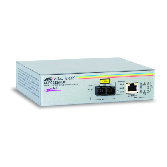
100Base-FX fiber media converter is designed for both standalone and wall mount use and does not require software configuration or management. Figure 1 illustrates the front panel of the AT-PC232/POE Media Converter. 1356 Figure 1. AT-PC232/POE Front Panel Figure 2 illustrates the back panel of the AT-PC232/POE Media Converter. -
Page 17: Key Features
AT-PC232/POE Media Converter Installation Guide Key Features The AT-PC232/POE Media Converter comes with the following features: One 10/100Base-TX twisted pair port with RJ-45 connector ❒ One 100Base-FX multi-mode fiber optic port with a duplex SC ❒ connector Supports half and full duplex operation ❒... -
Page 18: 10/100Base-Tx Twisted Pair Port
10/100Base-TX Twisted Pair Port The 10/100Base-TX twisted pair port is described below: Type of The 10/100Base-TX twisted pair port on AT-PC232/POE Media Converter features an 8-pin RJ-45 connector. The port uses four pins when Connector operating at 10 or 100 Mbps. For the port pinout details, refer to Figure 17 , “RJ-45 Connector and Port Pin Layout”... -
Page 19: Type Of Cabling
Category 5 or Enhanced Category 5 (5E) 100 ohm shielded or unshielded twisted pair cabling. Auto The 10/100Base-TX twisted pair port on the AT-PC232/POE Media Converter is auto-MDI/MDI-X and IEEE 802.3ab-compatible. The port MDI/MDI-X uses the auto-MDI/MDI-X feature to automatically configure itself as MDI or MDI-X when connected to an end-node. -
Page 20: 100Base-Fx Fiber Optic Port
The maximum operating distance of the port will be less Distance if it is operating in half-duplex mode. Type of Cable The fiber optic port on the AT-PC232/POE Media Converter uses multi- mode fiber optic cable. Optical Output Refer to “100Base-FX Port 1 Specifications” on page 55. -
Page 21: Operating Modes
AT-PC232/POE Media Converter Installation Guide Operating Modes The AT-PC232/POE Media Converter supports these operating modes: “Link Test Mode,” next “MissingLink Mode” on page 21 “Smart MissingLink Mode” on page 22 Link Test Mode Contrary to its name, the Link Test operating mode is not a diagnostic utility. -
Page 22: Smart Missinglink Mode
Link Test mode would probably be a better operating mode for the media converter during normal network operations. Furthermore, Allied Telesis does not recommend using the MissingLink mode when troubleshooting a network problem that may have its roots with a link problem. -
Page 23: Setting The Operating Mode
As with the other operating modes, this mode does not interfere with the flow of network traffic through the ports of a media converter during normal network operations of a media converter. However, Allied Telesis recommends limiting its use to diagnosing link failures, particularly if the network devices connected to the ports are managed devices. -
Page 24: Power Over Ethernet
(PD). Examples of such devices can be wireless access points, IP telephones, web cams, and Ethernet switches. There are several advantages that the PoE feature of the AT-PC232/POE Media Converter adds to the installation and maintenance of your network. -
Page 25: Power Budgeting
AT-PC232/POE Media Converter Installation Guide Power Budgeting The AT-PC232/POE Media Converter can provide a maximum of 15.4 W of power on its twisted pair port (Port 2), along with standard 10/100 Mbps Ethernet functionality. The AT-PC232/POE Media Converter smart power management functionality supports all of the IEEE 802.3af powered device classes... -
Page 26: Leds
Chapter 1: Overview LEDs The LEDs on the AT-PC232/POE Media Converter, are shown in Figure 3 and are described in the following sections: “Power LED” on page 26 ❒ “10/100Base-TX Twisted Pair Port LEDs” on page 27 ❒ “100Base-FX Fiber Optic Port LEDs” on page 27 ❒... -
Page 27: 10/100Base-Tx Twisted Pair Port Leds
Color Description Green A valid link has been established on the port. Blinking Indicates that when the AT-PC232/POE Media LINK Green Converter is in SML mode, the LINK on the 100BASE-FX port is lost. A port has not established a link with an end node. -
Page 28: Operating Mode Leds
Chapter 1: Overview Operating Mode The three LEDs listed under MODE on the front panel display the operating mode of the media converter. The LEDs are defined in Table 6 LEDs on page 28. Beside these LEDs is a button for setting the operating mode. Table 6. -
Page 29: Dip Switches
AT-PC232/POE Media Converter Installation Guide DIP Switches The DIP switches are used to manually configure the operating characteristics of the 10/100BASE-TX twisted-pair port (Port 2), such as port speed, duplex mode, and Auto-Negotation and the duplex mode for the 100BASE-FX fiber port (Port 1). For the DIP switch setting, refer to... -
Page 30: A Few Basics About Ethernet Switching
Ethernet frames. MAC Address The operation of the AT-PC232/POE Media Converter’s MAC address table reduces the amount of unnecessary traffic by not forwarding packets Table with a destination address that has been learned on the same port. -
Page 31: Network Topologies
AT-PC232/POE Media Converter Installation Guide Network Topologies Standalone A standalone topology uses only one AT-PC232/POE Media Converter between a switch and each end-node. Figure 4 illustrates an example of a Topology standalone topology where several AT-PC232/POE Media Converters are used to interconnect a number of PoE network Power Devices, such as VoIP phones, AT-7400 Wireless Access Points, and a network camera. -
Page 32: Back-To-Back Topology
AT-PC232/POE Media Converters which provide a connection of up to 2 kilometers (1.24 miles). The 10/100Base-TX twisted pair ports on the AT-PC232/POE Media Converters are connected to the SC ports on the switches, while the 100Base-FX ports on the two AT-PC232/POE Media Converters are directly connected to each other. -
Page 33: Chapter 2: Installation
AT-PC232/POE Media Converter Installation Guide Chapter 2 Installation This chapter explains how to install the AT-PC232/POE Media Converter and contains the following sections: “Verifying the Package Contents” on page 34 ❒ “Planning the Installation” on page 35 ❒ “Desktop Installation” on page 39 ❒... -
Page 34: Verifying The Package Contents
Chapter 2: Installation Verifying the Package Contents Make sure the following items are included in your package. If any item is missing or damaged, contact your Allied Telesis sales representative for assistance. One AT-PC232/POE Media Converter ❒ One AC power cord ❒... -
Page 35: Planning The Installation
The 10/100Base-TX twisted pair port may be set to match the speed ❒ and mode of the connected device or allowed to Auto-Negotiate. The end-node connected to a port on the AT-PC232/POE Media ❒ Converter can be any other ethernet network device, such as an adapter card, repeater, router, access point, or a switch. -
Page 36: Selecting A Site
Chapter 2: Installation Selecting a Site When selecting a site for your AT-PC232/POE Media Converter, observe the following guidelines: Select a site that is dust-free and moisture-free. ❒ The site should allow for easy access to the fiber optic and twisted pair ❒... - Page 37 The protection provided by the equipment may be impaired if the equipment is used in a manner not specified by Allied Telesis, Inc. Do not remove the cover from the unit or change any of the internal cables or wiring.
- Page 38 Caution: The unit does not contain serviceable components. Please return damaged units for servicing. Caution: The AT-PC232/POE Ethernet port is only intended for installation in Environment A as defined in IEEE 802.3af. All interconnected equipment must be contained in the same building including the interconnected equipment’s associated...
-
Page 39: Desktop Installation
AT-PC232/POE Media Converter Installation Guide Desktop Installation Install the AT-PC232/POE Media Converter on a desktop, perform the following procedure: 1. Remove the converter from its shipping container and store the packaging material in a safe location. 2. Turn the converter over and place it on a secure surface. -
Page 40: Wall-Mount Installation
Chapter 2: Installation Wall-Mount Installation The AT-PC232/POE Media Converter can be mounted vertically on a wall using the keyholes on the bottom of the switch. Two plastic anchors and screws necessary to mount the switch on a wall are provided in the accessory kit. -
Page 41: Cabling The Ports
Perform the following procedures to connect the network cables on the AT-PC232/POE Media Converter. Cabling the Fiber To connect to the fiber optic port (Port 1) on the AT-PC232/POE Media Converter, perform the following procedure. Optic Ports 1. Remove the dust cover from the fiber optic port, as shown in Figure 8 on page 41. -
Page 42: Connecting To The Copper Port
Figure 10. SC Ports 3. Connect the other end of the optical cable to the link partner. Connecting to the To connect a twisted pair cable to Port 2 on the AT-PC232/POE Media Converter, perform the following procedure: Copper Port 1. - Page 43 AT-PC232/POE Media Converter Installation Guide You can use a straight-through or crossover twisted pair cable to ❒ connect any type of network device to a port on the converter. 2. Connect the other end of the RJ-45 cable to the link partner.
-
Page 44: Configuring The Dip Switches
Chapter 2: Installation Configuring the DIP Switches Configure the DIP switches using the information in Table 10. Table 10. DIP Switch Settings Port Function Position Description Switch The twisted pair port operates at SPEED 10 Mbps.. (Mbps) DOWN The fiber port operates at 100 Mbps The fiber port operates in half-duplex mode. -
Page 45: Installing The Power Cord Retaining Clip
AT-PC232/POE Media Converter Installation Guide Installing the Power Cord Retaining Clip Perform the following procedure to install the power cord retaining clip on the AT-PC232/POE Media Converter: 1. Locate the power cord retaining clip, shown in Figure 12 in the shipping kit that comes with the media converter. -
Page 46: Applying Ac Power
Chapter 2: Installation Applying AC Power To apply AC power to the AT-PC232/POE Media Converter, perform the following procedure: 1. Position the power cord retaining clip in the up position, shown in Figure 14. S P E E (M b p... -
Page 47: Figure 16. Securing The Power Cord With The Retaining Clip
4. Connect the other end of the power cord to an appropriate AC power outlet. For the power specifications of the media converter, refer to “Electrical Rating” on page 53. The AT-PC232/POE Media Converter is now ready for network operations. -
Page 48: Verifying The Installation
Chapter 2: Installation Verifying the Installation This procedure is used to verify the installation of the media converter. It determines whether or not the fiber optic and twisted pair ports can establish links to their network devices. This procedure assumes the following: The media converter is powered on. -
Page 49: Chapter 3: Troubleshooting
Troubleshooting Here are suggestions on how to troubleshoot the twisted pair port and the fiber optic port on the AT-PC232/POE Media Converter. Problem 1: The two ports are connected to network devices, but the Link LEDs for the ports are off. - Page 50 Chapter 3: Troubleshooting Verify that the operating specifications of the fiber optic port on the remote network device are compatible with the port on the media converter. For port specifications, refer to “100Base-FX Port Specifications” on page 55. Verify that the correct type of fiber optic cabling is being used. For specifications, refer to “Fiber Optic Cabling and Distance Specifications”...
- Page 51 To identify which port is having the problem, use the Link Test mode. Note If you need further assistance, please contact Allied Telesis Technical Support. Refer to “Contacting Allied Telesis” on page 14. Section II: Advanced Operations...
- Page 52 Chapter 3: Troubleshooting Section II: Advanced Operations...
-
Page 53: Appendix A: Technical Specifications
Appendix A Technical Specifications Physical Dimensions: W x D x H 15.5 cm x 13.1 cm x 4.0 cm (6.10 in x 5.16 in x 1.58 in) Weight: .748 Kg (1.65 lb.) Temperature Operating Temperature: 0° C to 40° C (32° F to 104° F) Storage Temperature: -25°... -
Page 54: Agency Certifications
Chapter : Technical Specifications Agency Certifications RFI Emissions FCC Class B, EN55022 Class B, C-TICK, CE Immunity EN55024 Electrical Safety EN60950 (TUV), UL 60950 ( Standard IEEE 802.3, IEEE 802.3u RoHS RoHS/China RoHS compliant MTBF 580,000 Hrs 10/100Base-TX Port Pinouts Figure 17 illustrates the pin layout to an RJ-45 connector and port. -
Page 55: 100Base-Fx Port Specifications
AT-PC232/POE Media Converter Installation Guide Table 12 lists the RJ-45 port pin signals when a twisted pair port is operating in the MDI-X configuration at 10 or 100 Mbps. Table 2. MDI-X Pin Signals (10/100Base-TX) Signal 100Base-FX Port Specifications Table 13 lists the operating specifications for fiber port (Port 1) . - Page 56 Chapter : Technical Specifications...
-
Page 57: Appendix B: Cleaning Fiber Optic Connectors
Appendix B Cleaning Fiber Optic Connectors The fiber optic connector consists of a fiber optic plug and its adapter. The end of the fiber optic cable is held in the core of the ferrule in the plug. Light signals are transmitted through the core of the fiber. Even minor smudges or dirt on the end face of the fiber, completely invisible to the naked eye, can disrupt light transmission and lead to failure of the component or of the entire system. -
Page 58: Using A Cartridge-Type Cleaner
Appendix B: Cleaning Fiber Optic Connectors Using a Cartridge-Type Cleaner Fiber optic cartridge cleaners are available from many vendors and are typically called “cartridge cleaners,” as shown in Figure 20. Figure 20. Cartridge Cleaner Note Do not use compressed air or aerosol air to clean a fiber optic connector. -
Page 59: Figure 21. Rubbing The Ferrule Tip On The Cleaning Surface
AT-LX44000 Multi-Protocol WDM Transport System Installation Guide 2. Place the ferrule tip on the exposed cleaning surface and rub the ferrule in a downward direction, as shown in Figure 21. Figure 21. Rubbing the Ferrule Tip on the Cleaning Surface Note Rub the ferrule tip on the cleaning surface in one direction only. -
Page 60: Using A Swab
Appendix B: Cleaning Fiber Optic Connectors Using a Swab Specially treated swabs (stick cleaners) are available for cleaning inside connector adapters or hard-to-reach ferrule tips. These swabs, often referred to as “lint free” or “alcohol free” swabs, are available from many vendors, as shown in Figure 22. -
Page 61: Figure 23. Cleaning A Recessed Ferrule
AT-LX44000 Multi-Protocol WDM Transport System Installation Guide To clean a recessed ferrule using a swab, perform the following procedure. 1. Insert the swab into the adapter as shown in Figure 23 and rub the ferrule tip with the swab. Figure 23. Cleaning a Recessed Ferrule 2. - Page 62 Appendix B: Cleaning Fiber Optic Connectors...
Need help?
Do you have a question about the AT-PC232/POE and is the answer not in the manual?
Questions and answers