Table of Contents
Advertisement
Quick Links
Advertisement
Table of Contents

Related Manuals for Allied Telesis AT-iMG634 – R2


Summary of Contents for Allied Telesis AT-iMG634 – R2
- Page 1 AT-iMG634 – R2 USER MANUAL...
-
Page 2: Table Of Contents
All trademarks are the property of their respective owners. ATTENTION All the information in this manual is property of Allied Telesis, please do not copy or reproduce all or part of this manual without permission. Please see below for the meaning of the icons used in this manual. -
Page 3: Important Safety Instructions
1 IMPORTANT SAFETY INSTRUCTIONS DO NOT OPEN the product, remove screws or cover. To prevent ELECTRIC SHOCK during normal use, the plastic chassis of the product must be kept closed. This unit contains HAZARDOUS VOLTAGES and should only be opened by a trained and qualified technician. DANGER: DO NOT WORK on equipment or CABLES during periods of LIGHTNING ACTIVITY to avoid ELECTRIC SHOCK. -
Page 4: Important Notice
This could lead to fire or electric shock. Take care when handling the power cable and plug: Do not strain the power cable • Do not place near a heater or stove • Unplug the power cable using the plug •... -
Page 5: Contents Of The Package
3 CONTENTS OF THE PACKAGE The following items are included in the package. Contact your sales representative if any items are damaged or missing. 1. One AT-iMG634 – R2A or AT-iMG634 – R2B 2. One AC/DC power adapter 3. One CD user manual Power Adapter AT-iMG634WA/B CD User Manual... -
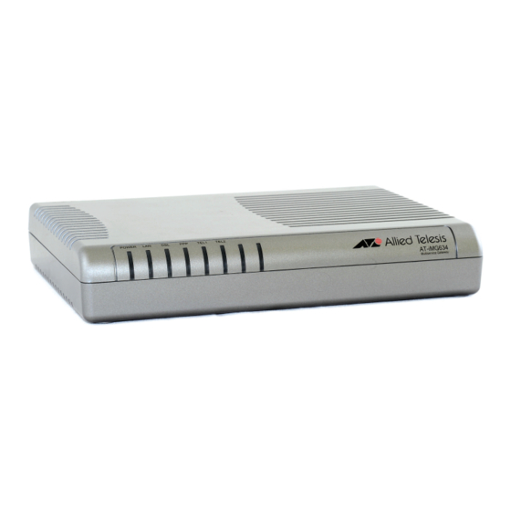
Page 6: Product Details
4 PRODUCT DETAILS Top view of unit WLAN Tel 1 Tel 2 ADSL Power/System Rear view of unit Antenna POWER ADSL (AT-iMG634W Only) -
Page 7: Led Description
LED description State Function The device is receiving power; Green light on voltage is within the acceptable range Red light on temporarily Boot phase Power/ after power on System Red light on An abnormal operating condition continuous Red light flashing Software upgrade in progress Red light off The system is working normally... -
Page 8: Rear Panel Ports And Button Description
Rear panel ports and button description Function Tel Port Connects analog telephone and fax through a telephone cord Used to reset the unit; it causes the default configuration to be loaded with the static IP address value of 192.168.1.1. Default To reset, press the ‘default’... -
Page 9: Unit Installation
5 UNIT INSTALLATION In order to be compliant with ITU-T K.21, the following auxiliary protection devices are required: 1. Primary protection device such as EPCOS B88069X4960T502 must be installed on the DSL Tip/Ring pair. Primary protection device installed on AC mains to limit surge energy into the Xavi unit’s PSU to 390V... -
Page 10: Connecting The At-Img634 - R2
CONNECTING THE AT-IMG634 – R2 ADSL cable connection Plug the ADSL cable into the ADSL port until you hear a “click” and make sure it is correctly fixed by lightly pulling the ADSL cable. In the same way, Connect the plug on the other end of the ADSL cable to the terminator. -
Page 11: Appendix - Technical Specifications
Appendix - Technical Specifications Interface 1 ADSL (6 pin RJ11 connector for Annex A, ADSL port 8 pin RJ45 connector for Annex B) 4 10/100BASE-TX (8 pin RJ45 connector) LAN port 2 FXS (6pin RJ11 connector) TEL port 802.11b/g WiFi Power 12V DC Input voltage...
Need help?
Do you have a question about the AT-iMG634 – R2 and is the answer not in the manual?
Questions and answers