Sign In
Upload
Download
Table of Contents
Contents
Add to my manuals
Delete from my manuals
Share
URL of this page:
HTML Link:
Bookmark this page
Add
Manual will be automatically added to "My Manuals"
Print this page
×
Bookmark added
×
Added to my manuals
Manuals
Brands
Allied Telesis Manuals
Gateway
iMG2400 Series
Installation manual
Allied Telesis iMG2400 Series Installation Manual
Hide thumbs
1
2
3
4
Table Of Contents
5
6
7
8
9
10
11
12
13
14
15
16
17
18
19
20
21
22
23
24
25
26
27
28
29
30
page
of
30
Go
/
30
Contents
Table of Contents
Troubleshooting
Bookmarks
Table of Contents
Table of Contents
Preface
Safety Symbols Used in this Document
Safety Precautions
Contacting Allied Telesis
Chapter 1: Technical Specifications
Electronics Overview
Figure 1: AT-Img2426F Electronics Unit
Physical Specifications
Environmental Specifications
Power Specifications
Safety and Electromagnetic Emissions Certifications
Power Cord Wiring
Figure 2: Gateway Terminal Block to Power Cord Terminal Block Wiring Diagram
Local Management Connection
Chapter 2: Installing the Gateway
Outdoor Installation
Required Tools and Supplies
Step 1: Check Package Contents
Step 2: Examine Outdoor Enclosure Configuration
Step 3: Check Power and Grounding
Figure 3: Enclosure (AT-EN-SFR-ONT) - Ready for the Electronics Unit
Figure 4: Ungrounded UPS Configuration (Recommended)
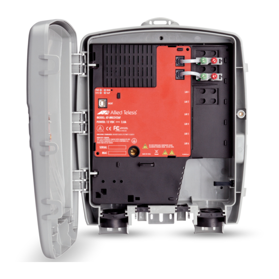
Step 4: Install the Electronics Unit into the Enclosure
Figure 5: Grounded UPS Configuration
Figure 6: Rear Connections
Figure 7: Slots for Connections
Figure 8: Snapping the Gateway into the Enclosure
Figure 9: Plugging in the DC Terminal Block
Figure 10: Routing the Jumper Cable through the Guides
Figure 11: Connecting the Telephone Wires
Figure 12: Connecting the LAN Cables
Indoor Installation
Using an Indoor AC Power Supply Unit (PSU) with the Img
Figure 13: Example of Completed Configuration
Chapter 3: Turn-Up and Troubleshooting
Turn-Up Sequence
Understanding the Leds
Figure 14: Leds
Troubleshooting
Advertisement
Quick Links
1
Electronics Overview
2
Local Management Connection
3
Figure 12: Connecting the Lan Cables
4
Turn-Up Sequence
5
Troubleshooting
Download this manual
iMG2400 Series
AT-iMG2426F
Installation Guide
613-001727 Rev. D
Table of
Contents
Previous
Page
Next
Page
1
2
3
4
5
Advertisement
Table of Contents
Troubleshooting
Chapter 3: Turn-Up and Troubleshooting
27
Troubleshooting
29
Need help?
Do you have a question about the iMG2400 Series and is the answer not in the manual?
Ask a question
Questions and answers
Related Manuals for Allied Telesis iMG2400 Series
Gateway Allied Telesis AT-iMG616BD Datasheet
Multiservice gateway with analog voip (2 pages)
Gateway Allied Telesis AT-iMG634 – R2 User Manual
(11 pages)
Gateway Allied Telesis AT-iMG616BD-R2 Specifications
Ftth multiservice gateway with analog voip (2 pages)
Gateway Allied Telesis AT-iMG646MOD Installation Manual
Enclosure and intelligent multiservice gateways (46 pages)
Gateway Allied Telesis AT-iMG616RF Specifications
Multiservice gateway with analog voip and fiber to rf catv transceiver (2 pages)
Gateway Allied Telesis AT-iMG606BD Installation Manual
Multiservice gateway (80 pages)
Gateway Allied Telesis AT-IMG616RF/RF+ Installation Manual
Multiservice voip gateway (21 pages)
Gateway Allied Telesis AT-iMG624 Datasheet
Adsl multiservice gateway with analog voip ports and wireless ieee 802.11b/g (2 pages)
Gateway Allied Telesis AT-iMG7x6MOD series Installation Manual
Enclosure and intelligent multiservice gateways (56 pages)
Gateway Allied Telesis AT-IMG646BD Datasheet
Ethernet intelligent multiservice gateway for outdoor deployment (3 pages)
Gateway Allied Telesis AT-RG600 Series Software Reference Manual
Residential gateway (464 pages)
Gateway Allied Telesis AT-PC232/POE Installation Manual
Fast ethernet media converter (62 pages)
Gateway Allied Telesis AT-iMG664A Specifications
Adsl2+ multiservice gateway with analog and digital voip and wireless ieee 802.11b/g (2 pages)
Gateway Allied Telesis AT-RG613 TX User Manual
Residential voip gateway (28 pages)
This manual is also suitable for:
At-img2426f
Table of Contents
Print
Rename the bookmark
Delete bookmark?
Delete from my manuals?
Login
Sign In
OR
Sign in with Facebook
Sign in with Google
Upload manual
Upload from disk
Upload from URL


Need help?
Do you have a question about the iMG2400 Series and is the answer not in the manual?
Questions and answers