Table of Contents
Advertisement
Quick Links
Advertisement
Table of Contents

Related Manuals for Supero X9DAi


Summary of Contents for Supero X9DAi
- Page 1 X9DAi USER’S MANUAL Revision 1.1c...
- Page 2 This product, including software and docu- mentation, is the property of Supermicro and/or its licensors, and is supplied only under a license. Any use or reproduction of this product is not allowed, except as expressly permitted by the terms of said license.
-
Page 3: About This Motherboard
(Socket R LGA 2011) that offer QPI (Intel QuickPath Interface) Technology (V.1.1), providing point-to-point connection with a transfer speed of up to 8.0 GT/s. With the C602 chipset built in, the X9DAi motherboard provides support for Intel Rapid Storage Technology, Digital Media Interface (DMI), PCI-E Gen. 3.0, and up to 1866 MHz DDR3 memory, greatly enhancing system performance for workstations and servers. -
Page 4: Conventions Used In The Manual
X9DAi Motherboard User's Manual Conventions Used in the Manual Pay special attention to the following symbols for proper system installation and to prevent damage to the system or injury to yourself: Warning: Important information given to ensure proper system installation or to prevent... -
Page 5: Contacting Supermicro
Super Micro Computer, Inc. 980 Rock Ave. San Jose, CA 95131 U.S.A. Tel: +1 (408) 503-8000 Fax: +1 (408) 503-8008 Email: marketing@supermicro.com (General Information) support@supermicro.com (Technical Support) Web Site: www.supermicro.com Europe Address: Super Micro Computer B.V. Het Sterrenbeeld 28, 5215 ML... -
Page 6: Table Of Contents
X9DAi Motherboard User's Manual Table of Contents Preface Chapter 1 Overview Overview ......................1-1 Processor and Chipset Overview..............1-11 Special Features ................... 1-12 PC Health Monitoring ..................1-12 ACPI Features ....................1-13 Power Supply ....................1-13 Super I/O ....................... 1-14 Chapter 2 Installation Standardized Warning Statements .............. - Page 7 Table of Contents Front Control Panel ..................2-23 Front Control Panel Pin Definitions............... 2-24 NMI Button ....................2-24 Power LED ....................2-24 HDD LED ....................2-25 NIC1/NIC2 LED Indicators ............... 2-25 Overheat (OH)/Fan Fail LED..............2-26 Power Fail LED ..................2-26 Reset Button ...................
- Page 8 X9DAi Motherboard User's Manual Chapter 3 Troubleshooting Troubleshooting Procedures ................3-1 Technical Support Procedures ................ 3-5 Battery Removal and Installation ..............3-6 Frequently Asked Questions ................3-7 Returning Merchandise for Service..............3-8 Chapter 4 BIOS Introduction ...................... 4-1 Main Setup ...................... 4-2 Advanced Setup Configurations..............
-
Page 9: Chapter 1 Overview
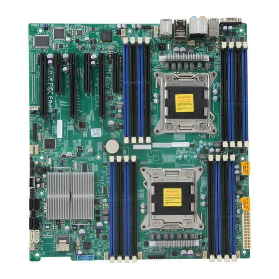
Checklist Congratulations on purchasing your computer motherboard from an acknowledged leader in the industry. Supermicro boards are designed with the utmost attention to detail to provide you with the highest standards in quality and performance. Please check that the following items have all been included with your motherboard. - Page 10 X9DAi Motherboard User's Manual Motherboard Image Note: All graphics shown in this manual were based upon the latest PCB Revision available at the time of publishing of the manual. The motherboard you've received may or may not look exactly the same as the graphics...
-
Page 11: Motherboard Layout
JBR1 JI2C2 CLK Buffer 1394a X9DAi Battery CTRL Rev. 1.02 JWD1 CPU1 Intel C602 JBT1 JOH1 BIOS I-SAS/ SATA0~3 FANA FAN6 (CPU1Fan) USB3.0 2/3 Note 1: For the latest CPU/Memory updates, please refer to our website at http://www.supermicro.com/products/motherboard/ for details. - Page 12 X9DAi Motherboard User's Manual X9DAi Quick Reference USB2.0 USB3.0 7.1 Audio 0/1/2/3 LAN1/2 COM1 Audio CPLD GLAN CTRL FAN5 CTRL FAN4 KB/MS S I/O FAN7 (CPU2 Fan) CPU2 JI2C1 JPME1 JBR1 JI2C2 CLK Buffer 1394a Battery X9DAi CTRL Rev. 1.02...
-
Page 13: Jumper Description
Chapter 1: Overview X9DAi Jumpers Jumper Description Default Setting J29/J30 SMB Enable Pins 1-2 (Enabled) JBT1 Clear CMOS See Chapter 2 C1/JI SMBus to PCI-E Slots Pins 2-3 (Normal) JPI1 IEEE1394a Enable Pins 1-2 (Enabled) JPL1/2 GLAN1/GLAN2 Enable Pins 1-2 (Enabled) - Page 14 X9DAi Motherboard User's Manual LAN1/2 G-bit Ethernet Ports 1/2 Onboard Buzzer (Internal Speaker) STBY1 Standby Power Header T-SGPIO 1/2 Serial-Link General_Purpose IO Headers 1/2 USB 2.0 0/1/2/3 Back Panel USB 2.0 Ports 0/1/2/3 USB 2.0 4, 5/6 Front Panel Accessible USB 2.0 Connections 4, 5/6 USB 3.0 0/1...
-
Page 15: Motherboard Features
Note 1: 1866 MHz memory support is depen- dent on Intel E5-2600v2 CPUs. Note 2: For the latest memory updates, please refer to the Tested Memory List posted on our website (http://www.supermicro.com/products/ motherboard). • Virtualization: VT-x, VT-d, and VT-c •... -
Page 16: Peripheral Devices
X9DAi Motherboard User's Manual Peripheral USB Devices Devices • Four (4) USB 3.0 ports: USB 3.0 Backplane Ports 0/1*, USB 3.0 Front Accessible Connections 2/3) • Seven (7) USB 2.0 Connections: Four (4): Backplane USB 2.0 (Ports 0~3), two (2): Front-Accessible (USB 4, USB 5/6), and •... - Page 17 • SuperDoctor® III, Watch Dog, NMI • Chassis Intrusion Header and Detection • Dimensions 12.00" (L) x 13.00" (W) (304.80 mm x 330.20 mm) Note 1: For updates on CPU and memory support, please refer to our website @ http://www.supermicro.com/support/manuals/.
- Page 18 X9DAi Motherboard User's Manual #1-4 #0-4 #1-3 #0-3 #1-2 #0-2 #1-1 E5-2600(v2) E5-2600(v2) #0-1 8GT/s DDR3 DDR3 DMI2 #2 #1B #3 #2 #1 DMI2 8GT/s PCI-Ex8 G3 PCI-E X16 G3 PCI-Ex16 G3 PCI-E X4 G3 PCI-E x8 G3 PCI-E x16 G3...
-
Page 19: Processor And Chipset Overview
Chapter 1: Overview Processor and Chipset Overview Built upon the functionality and the capability of the Intel E5-2600(v2) Series Processors (Socket R LGA 2011) and the C602 chipset, the X9DAi motherboard provides the performance and feature sets required for dual_processor-based workstation platforms. -
Page 20: Special Features
X9DAi Motherboard User's Manual Special Features Recovery from AC Power Loss The Basic I/O System (BIOS) provides a setting that determines how the system will respond when AC power is lost and then restored to the system. You can choose for the system to remain powered off (in which case you must press the power switch to turn it back on), or for it to automatically return to the power-on state. -
Page 21: Acpi Features
It is even more important for processors that have high CPU clock rates. The X9DAi motherboard accommodates 24-pin ATX power supplies. Although most power supplies generally meet the specifications required by the CPU, some are inadequate. In addition, two 12V 8-pin power connections are also required to ensure adequate power supply to the system. -
Page 22: Super I/O
X9DAi Motherboard User's Manual Super I/O The Super I/O supports one high-speed, 16550 compatible serial communication ports (UARTs). Each UART includes a 16-byte send/receive FIFO, a programmable baud rate generator, complete modem control capability and a processor interrupt system. Both UARTs provide legacy speed with baud rate of up to 115.2 Kbps as well as an advanced speed with baud rates of 250 K, 500 K, or 1 Mb/s, which support higher speed modems. -
Page 23: Chapter 2 Installation
The following statements are industry-standard warnings, provided to warn the user of situations which have the potential for bodily injury. Should you have questions or experience difficulty, contact Supermicro's Technical Support department for assis- tance. Only certified technicians should attempt to install or configure components. - Page 24 X9DAi Motherboard User's Manual Attention Danger d'explosion si la pile n'est pas remplacée correctement. Ne la remplacer que par une pile de type semblable ou équivalent, recommandée par le fabricant. Jeter les piles usagées conformément aux instructions du fabricant. ¡Advertencia! Existe peligro de explosión si la batería se reemplaza de manera incorrecta.
-
Page 25: Product Disposal
Chapter 2: Installation Product Disposal Warning! Ultimate disposal of this product should be handled according to all national laws and regulations. 製品の廃棄 この製品を廃棄処分する場合、 国の関係する全ての法律 ・ 条例に従い処理する必要が あります。 警告 本产品的废弃处理应根据所有国家的法律和规章进行。 警告 本產品的廢棄處理應根據所有國家的法律和規章進行。 Warnung Die Entsorgung dieses Produkts sollte gemäß allen Bestimmungen und Gesetzen des Landes erfolgen. -
Page 26: Static-Sensitive Devices
X9DAi Motherboard User's Manual القىانين واللىائح الىطنية جميع وفقا ل ينبغي التعامل معه هذا المنتج من التخلص النهائي عند 경고! 이 제품은 해당 국가의 관련 법규 및 규정에 따라 폐기되어야 합니다. Waarschuwing De uiteindelijke verwijdering van dit product dient te geschieden in overeenstemming met alle nationale wetten en reglementen. -
Page 27: Processor And Heatsink Installation
CPU socket cap is in place and none of the socket pins are bent; otherwise, contact your retailer immediately. • Refer to the Supermicro website for updates on CPU support. Installing the LGA2011 Processor 1. There are two load levers on the LGA2011 socket. To open the socket cover, first press and release the load lever labeled 'Open 1st'. - Page 28 X9DAi Motherboard User's Manual 2. Press the second load lever labeled 'Close 1st' to release the load plate that covers the CPU socket from its locking position. Pull lever away from Press down on Load the socket Lever 'Close 1st' 3.
- Page 29 Chapter 2: Installation 1. Using your thumb and the index finger, remove the 'WARNING' plastic cap from the socket. 2. Use your thumb and index finger to hold the CPU on its edges. Align the CPU keys, which are semi-circle cutouts, against the socket keys. Socket Keys CPU Keys 3.
- Page 30 X9DAi Motherboard User's Manual 4. With the CPU inside the socket, inspect the four corners of the CPU to make sure that the CPU is properly installed. 5. Close the load plate with the CPU inside the socket. Lock the 'Close 1st' lever first, then lock the 'Open 1st' lever second.
-
Page 31: Installing A Passive Cpu Heatsink
Chapter 2: Installation Installing a Passive CPU Heatsink 1. Do not apply any thermal grease to the heatsink or the CPU die -- the re- quired amount has already been applied. 2. Place the heatsink on top of the CPU so that the four mounting holes are aligned with those on the Motherboard's and the Heatsink Bracket under- neath. -
Page 32: Removing The Heatsink
X9DAi Motherboard User's Manual Removing the Heatsink Warning: We do not recommend that the CPU or the heatsink be removed. However, if you do need to uninstall the heatsink, please follow the instructions below to uninstall the heatsink to prevent damage done to the CPU or the CPU socket. -
Page 33: Installing And Removing The Memory Modules
Chapter 2: Installation Installing and Removing the Memory Modules Note: Check Supermicro's website for recommended memory modules. CAUTION Exercise extreme care when installing or removing DIMM modules to prevent any possible damage. Installing & Removing DIMMs 1. Insert the desired number of DIMMs into the memory slots, starting with P1-DIMMA1. - Page 34 X9DAi Motherboard User's Manual Memory Support for the X9DAi Motherboard The X9DAi motherboard supports up to 1 TB of Load Reduced (LRDIMM), 512 GB of Registered (RDIMM) or 128 GB of Unbuffered (UDIMM) ECC/Non-ECC DDR3 800/1066/1333/1600/1866 MHz 240-pin 4-channel memory modules in 16 DIMM slots.
- Page 35 1600 1866 1866 Note: For detailed information on memory support and updates, please refer to the SMC Recommended Memory List posted on our website at http://www.supermicro.com/support/resources/mem.cfm. Intel E5-2600(v2) Series Processor RDIMM Memory Support Ranks Memory Capacity Speed (MT/s) and Voltage Validated by Slot per Channel (SPC) and DIMM Per Channel...
- Page 36 1333, 1333 1333 Note: For detailed information on memory support and updates, please refer to the SMC Recommended Memory List posted on our website at http://www.supermicro.com/support/resources/mem.cfm. Populating RDIMM (ECC) Memory Modules Intel E5-2600 Series Processor RDIMM Memory Support Ranks Memory Capacity...
- Page 37 1066 1066 (QDP) Note: For detailed information on memory support and updates, please refer to the SMC Recommended Memory List posted on our website at http://www.supermicro.com/support/resources/mem.cfm. Intel E5-2600 Series Processor LRDIMM Memory Support Ranks Memory Speed (MT/s) and Voltage Validated by Slot per Channel (SPC) and DIMM Per...
-
Page 38: Motherboard Installation
X9DAi Motherboard User's Manual Motherboard Installation All motherboards have standard mounting holes to fit different types of chassis. Make sure that the locations of all the mounting holes for both motherboard and chassis match. Although a chassis may have both plastic and metal mounting fas- teners, metal ones are highly recommended because they ground the motherboard to the chassis. -
Page 39: Installing The Motherboard
Chapter 2: Installation Installing the Motherboard 1. Install the I/O shield into the chassis. 2. Locate the mounting holes on the motherboard. 3. Locate the matching mounting holes on the chassis. Align the mounting holes on the motherboard against the mounting holes on the chassis. 4. -
Page 40: Control Panel Connectors And I/O Ports
X9DAi Motherboard User's Manual Control Panel Connectors and I/O Ports The I/O ports are color coded in conformance with the industry standards. See the picture below for the colors and locations of the various I/O ports. Back Panel Connectors and I/O Ports USB2.0... -
Page 41: Serial Ports
CTRL FAN5 CTRL FAN4 KB/MS S I/O FAN7 (CPU2 Fan) 3. LAN2 CPU2 JI2C1 JPME1 JBR1 JI2C2 CLK Buffer 1394a Battery X9DAi CTRL Rev. 1.02 JWD1 CPU1 Intel C602 JBT1 JOH1 BIOS I-SAS/ SATA0~3 FANA FAN6 (CPU1Fan) USB3.0 2/3 2-19... -
Page 42: Atx Ps/2 Keyboard/Mouse Ports
X9DAi Motherboard User's Manual ATX PS/2 Keyboard/Mouse PS/2 Keyboard/Mouse Pin Ports Definitions PS2 Keyboard PS2 Mouse The ATX PS/2 keyboard and Pin# Definition Pin# Definition PS/2 mouse are located next to KB Data Mouse Data the Back Panel LAN ports 1/2 on... -
Page 43: Universal Serial Bus (Usb)
S I/O FAN7 (CPU2 Fan) 8. FP USB 2.0 Port 5/6 9. FP USB 3.0 Port 2/3 CPU2 JI2C1 JPME1 JBR1 JI2C2 CLK Buffer 1394a Battery X9DAi CTRL Rev. 1.02 JWD1 CPU1 Intel C602 JBT1 JOH1 BIOS I-SAS/ SATA0~3 FANA... -
Page 44: (Back_Panel) High Definition Audio (Hd Audio)
X9DAi Motherboard User's Manual (Back_Panel) High Definition Audio (BP) HD Audio (HD Audio) Conn# Signal This motherboard features a 7.1 Chan- SPDIF_Out nel High Definition Audio (HDA) codec Surround_Out that provides 8 DAC channels. The HD CEN/LFE_Out Audio connections simultaneously sup- Mic_In ports multiple-streaming 7.1 sound play-... -
Page 45: Front Control Panel
These connectors are designed specifically for use with Supermicro's server chassis. See the figure below for the descriptions of the various control panel buttons and LED indicators. Refer to the following section for descriptions and pin definitions. -
Page 46: Front Control Panel Pin Definitions
X9DAi Motherboard User's Manual Front Control Panel Pin Definitions NMI Button NMI Button Pin Definitions (JF1) The non-maskable interrupt button Pin# Definition header is located on pins 19 and 20 Control of JF1. Refer to the table on the right Ground for pin definitions. -
Page 47: Hdd Led
FAN7 (CPU2 Fan) Ground CPU2 Power LED JI2C1 JPME1 JBR1 JI2C2 HDD LED CLK Buffer NIC1 LED 1394a Battery X9DAi CTRL Rev. 1.02 NIC2 LED JWD1 CPU1 OH/Fan Fail LED Intel C602 PWR Fail LED JBT1 JOH1 Reset Reset Button... -
Page 48: Overheat (Oh)/Fan Fail Led
X9DAi Motherboard User's Manual Overheat (OH)/Fan Fail LED OH/Fan Fail/PWR Fail LED Pin Definitions (JF1) Connect an LED cable to pins 7 and 8 Pin# Definition of JF1 to provide advanced warnings of chassis overheating and fan failure. OH/Fan Fail LED) Refer to the table on the right for pin definitions. -
Page 49: Reset Button
Ground FAN7 (CPU2 Fan) CPU2 Power LED JI2C1 JPME1 HDD LED JBR1 JI2C2 CLK Buffer NIC1 LED 1394a Battery X9DAi CTRL Rev. 1.02 NIC2 LED JWD1 CPU1 OH/Fan Fail LED Intel C602 PWR Fail LED JBT1 JOH1 Reset Reset Button... -
Page 50: Connecting Cables
X9DAi Motherboard User's Manual Connecting Cables ATX Power 24-pin Connector Pin Definitions Pin# Definition Pin # Definition Power Connectors +3.3V +3.3V -12V +3.3V A 24-pin main power supply connector(J22) and two 8-pin CPU PWR connectors PS_ON (JPWR1/2) are located on the motherboard. -
Page 51: Fan Headers
E. Fan 5 F. Fan 6(CPU1 Fan) CPU2 G. Fan7(CPU2 Fan) H. Fan A I. Chassis Intrusion JI2C1 JPME1 JBR1 JI2C2 CLK Buffer 1394a Battery X9DAi CTRL Rev. 1.02 JWD1 CPU1 Intel C602 JBT1 JOH1 BIOS I-SAS/ SATA0~3 FANA FAN6 (CPU1Fan) USB3.0 2/3... -
Page 52: Internal Speaker
X9DAi Motherboard User's Manual Internal Speaker Internal Buzzer (SP1) Pin Definition The Internal Speaker, located at SP1, Pin# Definitions can be used to provide audible indica- Pin 1 Pos. (+) Beep In tions for various beep codes. See the Pin 2 Neg. -
Page 53: Tpm Header/Port 80 Header
CPLD GLAN CTRL FAN5 CTRL FAN4 KB/MS S I/O FAN7 (CPU2 Fan) CPU2 JI2C1 JPME1 JBR1 JI2C2 CLK Buffer 1394a Battery X9DAi CTRL Rev. 1.02 JWD1 CPU1 Intel C602 JBT1 JOH1 BIOS I-SAS/ SATA0~3 FANA FAN6 (CPU1Fan) USB3.0 2/3 2-31... -
Page 54: Power Smb (I 2 C) Connector
X9DAi Motherboard User's Manual Power SMB (I C) Connector PWR SMB Pin Definitions Power System Management Bus (I Pin# Definition Connector (JPI C1) monitors power Clock supply, fan and system temperatures. Data See the table on the right for pin PWR Fail definitions. -
Page 55: T-Sgpio 1/2 Headers
C. 1394a_1 CTRL FAN4 KB/MS S I/O FAN7 C. 1394a_2 (CPU2 Fan) CPU2 JI2C1 JPME1 JBR1 JI2C2 CLK Buffer 1394a Battery X9DAi CTRL Rev. 1.02 JWD1 CPU1 Intel C602 JBT1 JOH1 BIOS I-SAS/ SATA0~3 FANA FAN6 (CPU1Fan) USB3.0 2/3 2-33... -
Page 56: Spdif_In/Spdif_Out Headers
X9DAi Motherboard User's Manual SPDIF_In/SPDIF_Out Headers SPDIF_In SPDIF_Out Pin Definitions Pin Definitions The SPDIF_In (JSPDIF_In) and SP- Pin# Definition Pin# Definition DIF_Out (JSPDIF_Out) headers are S/PDIF_In S/PDIF_Out located next to the GLAN Controller Ground Ground on the motherboard. Place a cap on each header for audio support. -
Page 57: Overheat/Fan Fail Led
CPLD GLAN CTRL FAN5 CTRL FAN4 KB/MS S I/O FAN7 (CPU2 Fan) CPU2 JI2C1 JPME1 JBR1 JI2C2 CLK Buffer 1394a Battery X9DAi CTRL Rev. 1.02 JWD1 CPU1 Intel C602 JBT1 JOH1 BIOS I-SAS/ SATA0~3 FANA FAN6 (CPU1Fan) USB3.0 2/3 2-35... -
Page 58: Jumper Settings
X9DAi Motherboard User's Manual Jumper Settings Explanation of Jumpers Connector Pins To modify the operation of the mother- board, jumpers can be used to choose between optional settings. Jumpers cre- Jumper ate shorts between two pins to change the function of the connector. Pin 1... -
Page 59: Cmos Clear
CPLD GLAN CTRL FAN5 CTRL FAN4 KB/MS S I/O FAN7 (CPU2 Fan) CPU2 JI2C1 JPME1 JBR1 JI2C2 CLK Buffer 1394a Battery X9DAi CTRL Rev. 1.02 JWD1 CPU1 Intel C602 JBT1 JOH1 BIOS I-SAS/ SATA0~3 FANA FAN6 (CPU1Fan) USB3.0 2/3 2-37... -
Page 60: Ieee 1394A Enable
X9DAi Motherboard User's Manual IEEE 1394a Enable 1394a Enable/Disable Jumper Settings JPI1 allows you to enable or disable Both Jumpers Definition the onboard IEEE 1394a support. The Pins 1-2 Enabled default position is on pins 1 and 2 to Pins 2-3 Disabled use 1394_1 and 1394_2 connections. -
Page 61: Management Engine (Me) Recovery
CPLD GLAN CTRL FAN5 CTRL FAN4 KB/MS S I/O FAN7 (CPU2 Fan) CPU2 JI2C1 JPME1 JBR1 JI2C2 CLK Buffer 1394a X9DAi Battery CTRL Rev. 1.02 JWD1 CPU1 Intel C602 JBT1 JOH1 BIOS I-SAS/ SATA0~3 FANA FAN6 (CPU1Fan) USB3.0 2/3 2-39... -
Page 62: Onboard Led Indicators
X9DAi Motherboard User's Manual Onboard LED Indicators GLAN LEDs Activity LED Link LED Two LAN ports (LAN 1/LAN 2) are located Rear View (when facing the on the IO Backplane of the motherboard. rear side of the chassis) Each Ethernet LAN port has two LEDs. The... -
Page 63: 2-10 Serial Ata Connections
FAN7 (CPU2 Fan) D. I-SATA3 (SATA2) E. I-SATA4 (SATA2) F. I-SATA5 (SATA2) CPU2 G. I-SAS/SATA 0~3 JI2C1 JPME1 JBR1 JI2C2 CLK Buffer 1394a Battery X9DAi CTRL Rev. 1.02 JWD1 CPU1 Intel C602 JBT1 JOH1 BIOS I-SAS/ SATA0~3 FANA FAN6 (CPU1Fan) USB3.0 2/3... - Page 64 X9DAi Motherboard User's Manual Notes 2-42...
-
Page 65: Chapter 3 Troubleshooting
Chapter 3: Troubleshooting Chapter 3 Troubleshooting Troubleshooting Procedures Use the following procedures to troubleshoot your system. If you have followed all of the procedures below and still need assistance, refer to the ‘Technical Support Procedures’ and/or ‘Returning Merchandise for Service’ section(s) in this chapter. Note: Always disconnect the power cord before adding, changing or installing any hardware components. -
Page 66: System Boot Failure
X9DAi Motherboard User's Manual No Video 1. If the power is on, but you have no video, remove all the add-on cards and cables. 2. Use the speaker to determine if any beep codes exist. Refer to Appendix A for details on beep codes. -
Page 67: Memory Errors
2. Memory support: Make sure that the memory modules are supported by test- ing the modules using memtest86 or a similar utility. Note: Refer to the product page on our website http://www.supermicro. com for memory and CPU support and updates. - Page 68 X9DAi Motherboard User's Manual within the normal range. Also check the front panel Overheat LED, and make sure that the Overheat LED is not on. 5. Adequate power supply: Make sure that the power supply provides adequate power to the system. Make sure that all power connectors are connected.
-
Page 69: Technical Support Procedures
Technical Support Procedures Before contacting Technical Support, please take the following steps. Also, please note that as a motherboard manufacturer, Supermicro also sells motherboards through its channels, so it is best to first check with your distributor or reseller for troubleshooting services. -
Page 70: Battery Removal And Installation
X9DAi Motherboard User's Manual Battery Removal and Installation Battery Removal To remove the onboard battery, follow the steps below: 1. Power off your system and unplug your power cable. 2. Locate the onboard battery as shown below. 3. Using a tool such as a pen or a small screwdriver, push the battery lock out- wards to unlock it. -
Page 71: Frequently Asked Questions
Note: The SPI BIOS chip used on this motherboard cannot be removed. Send your motherboard back to our RMA Department at Supermicro for repair. For BIOS Recovery instructions, please refer to the AMI BIOS Recovery Instructions posted at http://www.supermicro.com. -
Page 72: Returning Merchandise For Service
X9DAi Motherboard User's Manual Returning Merchandise for Service A receipt or copy of your invoice marked with the date of purchase is required before any warranty service will be rendered. You can obtain service by calling your ven- dor for a Returned Merchandise Authorization (RMA) number. When returning the... -
Page 73: Chapter 4 Bios
BIOS Introduction This chapter describes the AMI BIOS Setup utility for the X9DAi. It also provides the instructions on how to navigate the AMI BIOS Setup utility screens. The AMI ROM BIOS is stored in a Flash EEPROM and can be easily updated. -
Page 74: Main Setup
X9DAi Motherboard User's Manual Note: For AMI UEFI BIOS Recovery, please refer to the UEFI BIOS Re- covery User Guide posted @http://www.supermicro.com/support/manuals/. Starting the Setup Utility Normally, the only visible Power-On Self-Test (POST) routine is the memory test. As the memory is being tested, press the <Delete> key to enter the main menu of the AMI BIOS Setup utility. - Page 75 This item displays the system date in Day MM/DD/YY format (e.g. Wed 10/12/2011). System Time This item displays the system time in HH:MM:SS format (e.g. 15:32:52). X9DAi SMC Version This item displays the SMC version of the BIOS ROM used in this system.
-
Page 76: Advanced Setup Configurations
X9DAi Motherboard User's Manual Advanced Setup Configurations Use the arrow keys to select Advanced Setup and press <Enter> to access the following submenu items. Boot Features Quiet Boot This feature allows the user to select bootup screen display between POST mes- sages and the OEM logo. -
Page 77: Power Configuration
Chapter 4: AMI BIOS Interrupt 19 Capture Interrupt 19 is the software interrupt that handles the boot disk function. When this item is set to Enabled, the ROM BIOS of the host adaptors will "capture" Interrupt 19 at bootup and allow the drives that are attached to these host adaptors to function as bootable disks. - Page 78 X9DAi Motherboard User's Manual • Minimum CPU Speed • Processor Cores • Intel HT (Hyper-Threading) Technology • Intel VT-x Technology • L1 Data Cache • L1 Code Cache • L2 Cache • L3 Cache CPU Speed This item displays the speed of the CPU installed in Socket 0.
- Page 79 Chapter 4: AMI BIOS codes to overwhelm the processor or damage the system during an attack. The default is Enabled. (Refer to Intel and Microsoft Web sites for more information.) Hardware Prefetcher (Available when supported by the CPU) If set to Enabled, the hardware prefetcher will prefetch streams of data and in- structions from the main memory to the L2 cache to improve CPU performance.
-
Page 80: Cpu Power Management Configuration
X9DAi Motherboard User's Manual Select Enabled to support the Low-power Compliance Mode for Energy-using Products (EuP). The options are Enable and Disable. CPU Power Management Configuration This submenu allows the user to configure the following CPU Power Manage- ment settings. - Page 81 Chapter 4: AMI BIOS CPU C7 Report (Available when Power Technology is set to Custom) Select Enabled to allow the BIOS to report the CPU C7 State (ACPI C3) to the operating system. CPU C7 State is a processor-specific low C-State. The options are Enabled and Disabled.
-
Page 82: Chipset Configuration
X9DAi Motherboard User's Manual Chipset Configuration North Bridge This feature allows the user to configure the settings for the Intel North Bridge. IOH Configuration Intel VT-d ® Select Enabled to enable Intel Virtualization Technology support for Direct I/O VT-d by reporting the I/O device assignments to the VMM (Virtual Machine Monitor) through the DMAR ACPI Tables. -
Page 83: Qpi Configuration
Chapter 4: AMI BIOS Port 1B Link Speed Select GEN1 to enable PCI-Exp Generation 1 support for Port 1B. Select GEN2 to enable PCI-Exp Generation 2 support for Port 1B. Select GEN3 to enable PCI-Exp Generation 3 support for Port 1B. The options are GEN1, GEN2, and GEN3. -
Page 84: Dimm Configuration
X9DAi Motherboard User's Manual QPI (Quick Path Interconnect) Link Speed Mode Use this feature to select data transfer speed for QPI Link connections. The options are Fast and Slow. QPI Link Frequency Select Use this feature to select the desired QPI frequency. The options are Auto, 6.4 GT/s, 7.2 GT/s, and 8.0 GT/s. - Page 85 Chapter 4: AMI BIOS usually in the form of a USB adaptor, can be used to enhance audio performance. Select Unhide to display the Perfmon and DXF devices installed in the system. The options are HIDE and UNHIDE. DRAM RAPL Mode RAPL which stands for Running Average Power Limit is a feature that provides mechanisms to enforce power consumption limits on supported processors The options are DRAM RAPL MODE0 , DRAM RAPL MODE1, and Disabled.
-
Page 86: South Bridge Configuration
X9DAi Motherboard User's Manual Data Scrambling Select Enabled to enable data scrubbing and ensure data security and integrity. The options are Disabled and Enabled. DRAM RAPL (Running Average Power Limit) This item allows the user to select the average power limit setting when a DRAM module is in operation. -
Page 87: Audio Configuration
Chapter 4: AMI BIOS Legacy USB Support (Available when USB Functions is not Disabled) Select Enabled to support legacy USB devices. Select Auto to disable legacy sup- port if USB devices are not present. Select Disabled to have USB devices available for EFI (Extensive Firmware Interface) applications only. -
Page 88: Sas Configuration
X9DAi Motherboard User's Manual IDE Mode The following items are displayed when IDE Mode is selected: Serial-ATA (SATA) Controller 0~1 Use this feature to activate or deactivate the SATA controller, and set the compatibility mode. The options are Enhanced and Compatible. The default for SATA controller 0 is Compatible. -
Page 89: Thermal Configuration
Chapter 4: AMI BIOS OnChip SAS Oprom Select Enabled to support the onboard SAS Option ROM to boot up the system via a storage device. The options are Disabled and Enabled. Thermal Configuration Thermal Management Select Enabled to initialize the PCH Thermal subsystem device. The options are Enabled and Disabled. - Page 90 X9DAi Motherboard User's Manual Above 4G Decoding (Available if the system supports 64-bit PCI decoding) Select Enabled to decode a PCI device that supports 64-bit in the space above 4G Address. The options are Enabled and Disabled. PERR# Generation Select Enabled to allow a PCI device to generate a PERR number for a PCI Bus Signal Error Event.
-
Page 91: Super Io Configuration
Chapter 4: AMI BIOS VGA Priority This feature allows the user to select the graphics adapter to be used as the primary boot device. The options are Onboard, and Offboard. Network Stack Select Enabled enable PXE (Preboot Execution Environment) or UEFI (Unified Extensible Firmware Interface) for network stack support. -
Page 92: Serial Port Console Redirection
X9DAi Motherboard User's Manual Watch Dog Function If enabled, the Watch Dog timer will allow the system to automatically reboot when a non-recoverable error occurs that lasts for more than five minutes. The options are Enabled and Disabled. Serial Port Console Redirection... - Page 93 Chapter 4: AMI BIOS the data bits. Select Space to add a Space as a parity bit to be sent with your data bits. The options are None, Even, Odd, Mark and Space. Stop Bits A stop bit indicates the end of a serial data packet. Select 1 Stop Bit for standard serial data communication.
-
Page 94: Hardware Health Configuration
X9DAi Motherboard User's Manual Console Redirection (for EMS) Select Enabled to use a COM Port selected by the user for Console Redirection. The options are Enabled and Disabled. Console Redirection Settings (for EMS) This feature allows the user to specify how the host computer will exchange data with the client computer, which is the remote computer used by the user. -
Page 95: Acpi Setting
Chapter 4: AMI BIOS CPU Temperature Display Mode This feature displays the CPU temperature detected by DTS (i.e., +34 C) or temper- ature status in text ("Low", "Medium" or "High"). The options are Text Mode or DTS. If Text Mode is selected, the CPU Temperature Display Mode will show the CPU temperature status as follows: CPU 1 Temperature/CPU 2 Temperature The CPU Temperature feature will display the CPU temperature status as detected... - Page 96 X9DAi Motherboard User's Manual ACPI Sleep State Use this feature to select the ACPI State when the system is in sleep mode. Select S1 (CPU_Stop_Clock) to erase all CPU caches and stop executing instructions. Power to the CPU(s) and RAM is maintained, but RAM is refreshed. Select Suspend Disabled to use power-reduced mode.
- Page 97 Chapter 4: AMI BIOS ME Subsystem This feature displays the following ME Subsystem Configuration settings. ME (Management Engine) Subsystem Select Enabled to enable support for Intel Management Engine Subsystem that carry out various tasks in the background to enhance overall system performance. The options are Enabled and Disabled.
-
Page 98: Event Logs
X9DAi Motherboard User's Manual Event Logs Use this feature to configure Event Log settings. Change SMBIOS Event Log Settings This feature allows the user to configure SMBIOS Event settings. Enabling/Disabling Options SMBIOS Event Log Select Enabled to enable SMBIOS (System Management BIOS) Event Logging during system boot. - Page 99 Chapter 4: AMI BIOS Erasing Settings Erase Event Log Select Enabled to erase the SMBIOS (System Management BIOS) Event Log, which is completed before a event logging is initialized upon system reboot. The options are No, Yes Next Reset, and Yes Every Reset. When Log is Full Select Erase Immediately to immediately erase SMBIOS error event logs that exceed the limit when the SMBIOS event log is full.
-
Page 100: Boot
X9DAi Motherboard User's Manual Boot This submenu allows the user to configure the following boot settings for the system. Boot Option Priorities Boot Option #1/ Boot Option #2/ Boot Option #3 Use this feature to specify the sequence of boot device priority. -
Page 101: Security
Chapter 4: AMI BIOS Security This menu allows the user to configure the following security settings for the system. Administrator Password Use this feature to set the Administrator Password which is required to enter the BIOS setup utility. The length of the password should be from 3 to 20 characters long. -
Page 102: Save & Exit
X9DAi Motherboard User's Manual Save & Exit This submenu allows the user to configure the Save and Exit settings for the system. Discard Changes and Exit Select this option to quit the BIOS Setup without making any permanent changes to the system configuration, and reboot the computer. Select Discard Changes and Exit, and press <Enter>. - Page 103 Chapter 4: AMI BIOS if you want to save configuration, select Yes to save the changes, or select No to return to the BIOS without making changes. Discard Changes Select this feature and press <Enter> to discard all the changes and return to the BIOS setup.
- Page 104 X9DAi Motherboard User's Manual Notes 4-32...
-
Page 105: Appendix A Bios Error Beep Codes
Appendix A: BIOS POST Error Codes Appendix A BIOS Error Beep Codes During the POST (Power-On Self-Test) routines, which are performed at each system boot, errors may occur. Non-fatal errors are those which, in most cases, allow the system to continue to boot. - Page 106 X9DAi Motherboard User’s Manual Notes...
-
Page 107: Appendix B Software Installation Instructions
To install these programs, click the icons to the right of these items. Note: To install the Windows OS, please refer to the instructions posted on our Website at http://www.supermicro.com/support/manuals/. Driver/Tool Installation Display Screen Note 1: Click the icons showing a hand writing on the paper to view the readme files for each item. -
Page 108: Configuring Superdoctor® Iii
X9DAi Motherboard User's Manual B-2 Configuring SuperDoctor ® The SuperDoctor® III program is a Web-based management tool that supports remote management capability. It includes Remote and Local Management tools. The local management is called the SD III Client. The SuperDoctor III program included on the CDROM that came with your motherboard allows you to monitor the environment and operations of your system. - Page 109 Appendix B: Software Installation Instructions SuperDoctor® III Interface Display Screen-II (Remote Control) Note: The SDIII utility and the user guide can be downloaded from our website at: http://www.supermicro.com/products/accessories/software/ SuperDoctorIII.cfm. For Linux, we will still recommend that you use SuperDoctor II.
- Page 110 X9DAi Motherboard User's Manual Notes...
- Page 111 (Disclaimer Continued) The products sold by Supermicro are not intended for and will not be used in life support systems, medical equipment, nuclear facilities or systems, aircraft, aircraft devices, aircraft/emergency communication devices or other critical systems whose failure to perform be reasonably expected to result in significant injury or loss of life or catastrophic property damage.
Need help?
Do you have a question about the X9DAi and is the answer not in the manual?
Questions and answers