Table of Contents
Advertisement
Quick Links
Advertisement
Table of Contents

Related Manuals for Supero Supero X9DBS-F


Summary of Contents for Supero Supero X9DBS-F
- Page 1 X9DBS-F X9DBS-F-2U USER’S MANUAL Revision 1.0...
- Page 2 This product, including software and docu- mentation, is the property of Supermicro and/or its licensors, and is supplied only under a license. Any use or reproduction of this product is not allowed, except as expressly permitted by the terms of said license.
-
Page 3: About This Motherboard
Management Engine (ME), Rapid Storage Technology, Digital Media Interface (DMI), PCI-E Gen. 3.0, and DDR3 memory of up to 1600 MHz, greatly enhancing system performance. This motherboard is intended to be used in Supermicro SBB platforms. Please refer to our website at http://www.supermicro.com for processor and memory update and support. -
Page 4: Conventions Used In The Manual
X9DBS-F/X9DBS-F-2U Motherboard User’s Manual Conventions Used in the Manual Pay special attention to the following symbols for proper system installation and to prevent damage to the system or injury to yourself: Warning: Important information is given to ensure proper system installation or to avoid causing damage to the system or causing injury to yourself. -
Page 5: Contacting Supermicro
Super Micro Computer, Inc. 980 Rock Ave. San Jose, CA 95131 U.S.A. Tel: +1 (408) 503-8000 Fax: +1 (408) 503-8008 Email: marketing@supermicro.com (General Information) support@supermicro.com (Technical Support) Web Site: www.supermicro.com Europe Address: Super Micro Computer B.V. Het Sterrenbeeld 28, 5215 ML... -
Page 6: Table Of Contents
X9DBS-F/X9DBS-F-2U Motherboard User’s Manual Table of Contents Preface Chapter 1 Overview Overview ......................1-1 Processor and Chipset Overview..............1-11 Special Features ................... 1-12 PC Health Monitoring ..................1-12 ACPI Features ....................1-13 Power Supply ....................1-13 Super I/O ....................... 1-13 Advanced Power Management ..............1-14 Intel Intelligent Power Node Manager (IPNM) .......... - Page 7 Table of Contents Jumper Settings .................... 2-22 Explanation of Jumpers ................2-22 Watch Dog Enable/Disable ..............2-22 CMOS Clear ..................... 2-23 GLAN Enable/Disable ................2-23 Onboard LED Indicators ................2-25 LAN1/LAN2 LEDs ..................2-25 BMC Heartbeat/System Heartbeat LED ........... 2-26 Onboard Power LED ................
- Page 8 X9DBS-F/X9DBS-F-2U Motherboard User’s Manual Notes viii...
-
Page 9: Chapter 1 Overview
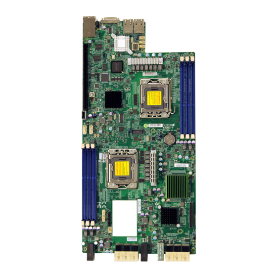
Checklist Congratulations on purchasing your computer motherboard from an acknowledged leader in the industry. Supermicro boards are designed with the utmost attention to detail to provide you with the highest standards in quality and performance. This motherboard is intended to be used in Supermicro's 2U/3U SBB chassis as an integrated platform solution. - Page 10 X9DBS-F/X9DBS-F-2U Motherboard User’s Manual Motherboard Image Note: All graphics shown in this manual were based upon the latest PCB revision available at the time of publishing of the manual. The motherboard you've received may or may not look exactly the same as the graphics shown in this manual.
-
Page 11: Motherboard Layout
External SAA JKVM1 VGA/USB/COM1 LAN2 LAN1 Fan 6 Fan 5 Intel i350 Fan 4 Re-Driver Re-Driver X9DBS-F Rev. 1.01 CPU1 JBT1 BIOS Battery CPU2 LED10 Note : For the latest CPU/Memory updates, please refer to our website at http://www.supermicro.com/products/motherboard/ for details. - Page 12 X9DBS-F/X9DBS-F-2U Motherboard User’s Manual X9DBS-F/X9DBS-F-2U Jumpers External SAA JKVM1 VGA/USB/COM1 LAN2 LAN1 Fan 6 Fan 5 Intel i350 Fan 4 Re-Driver Re-Driver X9DBS-F Rev. 1.01 CPU1 JBT1 BIOS Battery CPU2 LED10 Notes: • See Chapter 2 for detailed information on jumpers, I/O ports and JF1 front panel connections.
- Page 13 Chapter 1: Overview X9DBS-F/X9DBS-F-2U Jumpers Jumper Description Default Setting JBT1 Clear CMOS See Chapter 3 C1/JI SMB to PCI-E Slots Open (Normal) JPL1 GLAN 1/2 Enable Pins 1-2 (Enabled) JPME1 ME Firmware Pins 1-2 (Normal) JPME2 ME Mode (Select) Pins 1-2 (Normal) JWD1 Watch Dog Pins 1-2 (Reset)
-
Page 14: Motherboard Features
X9DBS-F/X9DBS-F-2U Motherboard User’s Manual Motherboard Features • Dual Intel E5-2400 (Socket B2 up to 95W) proces- ® sors; each processor supports two full-width Quick- Path Interconnect (QPI) links of up to 8.0 GT/s per link and with data transfer rate of up to 16 GB/s direction peak bandwidth per port •... - Page 15 Chapter 1: Overview IPMI 2.0 • Nuvoton WPCM450R Base-board Controller (BMC) supports IPMI_LAN 2.0 Serial (COM) Port • One (1) External UART • One (1) Internal UART to the Backplane Keyboard/Mouse/VGA • Back Panel Keyboard/VGA/Mouse UIO Platform • PCI-E 3.0 x24 for 2U/3U Riser Card Peripheral USB Devices Devices...
- Page 16 Note 1: CPU Maximum Thermal Design Power (TDP) is subject to chassis and heatsink cooling restrictions. For proper thermal management, please check the chassis and heatsink specifications for proper CPU TDP sizing. Note 2: For IPMI Configuration Instructions, please refer to the Embedded IPMI Configuration User's Guide available @ http://www.supermicro.com/ support/manuals/.
- Page 17 Chapter 1: Overview Notes...
-
Page 18: System Block Diagram
X9DBS-F/X9DBS-F-2U Motherboard User’s Manual CPU2 CPU1 Rear (IO Side) E5-2400 Series Processor E5-2400 Series Processor DDRIII DDRIII PE1A [3..0] PE3B [7:4] PE3C [3:0] PE1A [3..0] PE3B [7:4] PE1B [7..4] PE3A [3:0] PE3D [7:4] PE1B [7..4] PE3A [3:0] PE3D [7:4] PE3C [3:0] DMI2 PCI-E x24 230 pins NTB x8... -
Page 19: Processor And Chipset Overview
Chapter 1: Overview Processor and Chipset Overview Built upon the functionality and the capabilities of the Intel E5-2400 (Socket B2) processor and the C602J chipset, the X9DBS-F/X9DBS-F-2U motherboard provides the performance and feature sets required for dual_processor-based SBB platforms. With support of Intel QuickPath interconnect (QPI) Technology, the X9DBS-F/ X9DBS-F-2U motherboard offers point-to-point serial interconnect interface with a transfer speed of up to 8.0 GT/s, providing superb system performance. -
Page 20: Special Features
X9DBS-F/X9DBS-F-2U Motherboard User’s Manual Special Features Recovery from AC Power Loss The Basic I/O System (BIOS) provides a setting that determines how the system will respond when AC power is lost and then restored to the system. You can choose for the system to remain powered off (in which case you must press the power switch to turn it back on), or for it to automatically return to the power-on state. -
Page 21: Acpi Features
Chapter 1: Overview and fan speeds go beyond a predefined range. ACPI Features ACPI stands for Advanced Configuration and Power Interface. The ACPI specifica- tion defines a flexible and abstract hardware interface that provides a standard way to integrate power management features throughout a PC system, including hardware, operating system and application software. -
Page 22: Advanced Power Management
• Use a power supply that supports PMBus 1.1 or 1.2. • Install the NMView software in your system. NMView is optional and can be purchased from Supermicro. Intel Intelligent Power Node Manager (IPNM) ® The Intel Intelligent Power Node Manager (IPNM) provides your system with ®... -
Page 23: Wpcm450R Ddr2 Memory Interface
Chapter 1: Overview control Super IO functions. The WPCM450R Controller is connected to the network via an external Ethernet PHY module or shared NCSI connections. The WPCM450R communicates with onboard components via six SMBus inter- faces, PECI (Platform Environment Control Interface) buses, and General Purpose I/O ports. - Page 24 Provides Network Management Security via remote access/console redirec- tion. • Supports the following Management tools: IPMIView, CLI (Command Line Interface) • RMCP+ protocol supported Note: For more information on IPMI configuration, please refer to the IPMI User's Guide posted on our website at http://www.supermicro.com/ support/manuals/. 1-16...
-
Page 25: Chapter 2 Installation
The following statements are industry-standard warnings, provided to warn the user of situations which have the potential for bodily injury. Should you have questions or experience difficulty, contact Supermicro's Technical Support department for assis- tance. Only certified technicians should attempt to install or configure components. - Page 26 X9DBS-F/X9DBS-F-2U Motherboard User’s Manual Attention Danger d'explosion si la pile n'est pas remplacée correctement. Ne la remplacer que par une pile de type semblable ou équivalent, recommandée par le fabricant. Jeter les piles usagées conformément aux instructions du fabricant. ¡Advertencia! Existe peligro de explosión si la batería se reemplaza de manera incorrecta.
-
Page 27: Product Disposal
Chapter 2: Installation Product Disposal Warning! Ultimate disposal of this product should be handled according to all national laws and regulations. 製品の廃棄 この製品を廃棄処分する場合、 国の関係する全ての法律 ・ 条例に従い処理する必要が あります。 警告 本产品的废弃处理应根据所有国家的法律和规章进行。 警告 本產品的廢棄處理應根據所有國家的法律和規章進行。 Warnung Die Entsorgung dieses Produkts sollte gemäß allen Bestimmungen und Gesetzen des Landes erfolgen. -
Page 28: Static-Sensitive Devices
X9DBS-F/X9DBS-F-2U Motherboard User’s Manual القىانين واللىائح الىطنية جميع وفقا ل ينبغي التعامل معه هذا المنتج من التخلص النهائي عند 경고! 이 제품은 해당 국가의 관련 법규 및 규정에 따라 폐기되어야 합니다. Waarschuwing De uiteindelijke verwijdering van dit product dient te geschieden in overeenstemming met alle nationale wetten en reglementen. -
Page 29: Processor And Heatsink Installation
Chapter 2: Installation Processor and Heatsink Installation When handling the processor package, avoid placing direct pressure on the label area of the fan. Notes: 1. Always connect the power cord last, and always remove it before adding, removing, or changing any hardware components. Make sure that you install the processor into CPU socket 1 first. - Page 30 X9DBS-F/X9DBS-F-2U Motherboard User’s Manual 4. After removing the plastic cap, hold the CPU at the north and south center edges with your thumb and index finger,. 5. Align the CPU key, which is a semi-circle cutout, with the socket key, which is the notch below the gold color dot on the side of the socket.
-
Page 31: Installing A Passive Cpu Heatsink
Chapter 2: Installation Installing a Passive CPU Heatsink 1. Apply the proper amount of thermal grease to the heatsink. 2. Place the heatsink on top of the CPU so that the two mounting holes on the heatsink are aligned with those on the retention mechanism. 3. -
Page 32: Removing The Passive Heatsink
X9DBS-F/X9DBS-F-2U Motherboard User’s Manual Removing the Passive Heatsink Warning: We do not recommend that the CPU or the heatsink be removed. However, if you do need to remove the heatsink, please follow the instructions below to uninstall the heatsink to avoid damaging the CPU or other components. 1. -
Page 33: Installing And Removing The Memory Modules
Chapter 2: Installation Installing and Removing the Memory Modules Note: Check Supermicro's website for recommended memory modules. CAUTION Exercise extreme care when installing or removing DIMM modules to prevent any possible damage. Installing & Removing DIMMs 1. Insert the desired number of DIMMs into the memory slots, starting with P1- DIMM #A1. - Page 34 ECC/Non-ECC DDR3 memory with speeds of 1600/1333/1066/800 MHz in 6 DIMM slots. For the latest memory updates, please refer to our website a at http://www. supermicro.com/products/motherboard. Processor & Memory Module Population Configuration For memory to work properly, follow the tables below for memory installation.
- Page 35 1066, 1333, 1600 DRx4 16GB 1066, 1333 1066, 1333, 1600 QRx4 16GB 32GB QRx8 16GB Note: For detailed information on memory support and updates, please refer to the SMC Recommended Memory List posted on our website at http://www.supermicro. com/support/resources/mem.cfm. 2-11...
- Page 36 Note: For detailed information on memory support and updates, please refer to the SMC Recommended Memory List posted on our website at http://www. supermicro.com/support/resources/mem.cfm. Other Important Notes and Restrictions • For the memory modules to work properly, please install DIMM modules of the same type, same speed and same operating frequency on the motherboard.
-
Page 37: Motherboard Installation
Chapter 2: Installation Motherboard Installation All motherboards have standard mounting holes to fit different types of chassis. Make sure that the locations of all the mounting holes for both motherboard and chassis match. Although a chassis may have both plastic and metal mounting fas- teners, metal ones are highly recommended because they ground the motherboard to the chassis. -
Page 38: Installing The Motherboard
X9DBS-F/X9DBS-F-2U Motherboard User’s Manual Installing the Motherboard 1. Install the I/O shield into the chassis. 2. Locate the mounting holes on the motherboard. 3. Locate the matching mounting holes on the chassis. Align the mounting holes on the motherboard with the mounting holes on the chassis. 4. -
Page 39: Control Panel Connectors And I/O Ports
Chapter 2: Installation Control Panel Connectors and I/O Ports The I/O ports are color-coded in conformance with the PC 99 specification. See the picture below for the colors and locations of the various I/O ports. Back Panel Connectors and I/O Ports X9DBS-F Rev. -
Page 40: Keyboard/Video/Mouse
X9DBS-F/X9DBS-F-2U Motherboard User’s Manual Keyboard/Video/Mouse A keyboard/video/mouse connector (JKVM1) is located next to LAN Ports 1/2 on the motherboard. See the lay- out below for the location of JKVM1. Ethernet Ports LAN Ports Pin Definition Two Gigabit_LAN ports (LAN1/LAN2) Pin# Definition are located on the I/O backplane on P2V5SB SGND... -
Page 41: External Sas Connectors
Chapter 2: Installation External SAS Connectors Two External Serial Attached SCSI Ports are located on the backplane of the X9D- BS-F, while only one located on the backplane on the X9DBS-F-2U. These SATA connectors provide serial link connections. See the layout below for the location. Note: For more information on SATA connections, refer to Section 2-10 in the end of this chapter. -
Page 42: Connecting Cables
X9DBS-F/X9DBS-F-2U Motherboard User’s Manual Connecting Cables Fan Headers Fan Header Pin Definitions This motherboard has three system/CPU Pin# Definition fan headers (Fan1-Fan 6) on the moth- Ground erboard. All these 4-pin fans headers are +12V backward compatible with the traditional Tachometer 3-pin fans. -
Page 43: Overheat/Fan Fail Led
Chapter 2: Installation Overheat/Fan Fail LED OH/Fan Fail LED The JOH1 header is used to connect Status an LED indicator to provide warnings State Message of chassis overheating and fan failure. Solid Overheat This LED will blink when a fan failure Blinking Fan Fail occurs. -
Page 44: Sata Dom Power Connectors
X9DBS-F/X9DBS-F-2U Motherboard User’s Manual SATA DOM Power Connectors DOM PWR Pin Definitions Two power connectors for SATA DOM Pin# Definition (Disk On Module) devices are located at JSD1/JSD2. Connect appropriate Ground cables here to provide power support Ground for your DOM devices. Universal Serial Bus (USB) Type A USB Pin Definitions... -
Page 45: Me Firmware
Chapter 2: Installation ME Firmware ME Firmware Jumper Settings Use Jumper JPME1 to select ME Firmware Jumper Setting Definition Recovery mode, which will limit resource al- Normal (Default) location for essential system operation only in ME Recovery order to maintain normal power operation and management. -
Page 46: Jumper Settings
X9DBS-F/X9DBS-F-2U Motherboard User’s Manual Jumper Settings Explanation of Jumpers Connector Pins To modify the operation of the motherboard, jumpers can be used to choose between optional settings. Jumpers create shorts be- Jumper tween two pins to change the function of the connector. -
Page 47: Cmos Clear
Chapter 2: Installation CMOS Clear JBT1 is used to clear CMOS. Instead of pins, this "jumper" consists of contact pads to prevent accidental clearing of CMOS. To clear CMOS, use a metal object such as a small screwdriver to touch both pads at the same time to short the connec- tion. - Page 48 X9DBS-F/X9DBS-F-2U Motherboard User’s Manual C Bus to PCI-Exp. Slots C to PCI-Exp Jumper Settings Jumpers JI C1 and JI C2 allow you to Jumper Setting Definition connect the System Management Bus Closed Enabled C) to the PCI-Express slot (Slot1) Open Disabled (Default) on the motherboard.
-
Page 49: Onboard Led Indicators
Chapter 2: Installation Onboard LED Indicators Link LED Activity LED LAN1/LAN2 LEDs G_LAN Ports 1/2 (JLAN1/JLAN2) are lo- Rear View (when facing the rear side of the chassis) cated on the IO Backplane. Each Ethernet LAN 1/LAN 2 Activity LED (Right) LAN port has two LEDs. -
Page 50: Bmc Heartbeat/System Heartbeat Led
X9DBS-F/X9DBS-F-2U Motherboard User’s Manual BMC Heartbeat/System Heartbeat LED BMC Heartbeat/System Heartbeat LED A BMC/System Heartbeat LED is located Status at D95 on the motherboard. When D95 is Color/State Definition up, it functions as a BMC Heartbeat LED. D95: Up BMC Heartbeat When D95 is down, it is used as a System D95: Down System Heart-... -
Page 51: Sata Heartbeat Led
Chapter 2: Installation SATA Heartbeat LED SATA Heartbeat LED Status A SATA Heartbeat LED is located at LED2 Color/State Definition on the motherboard. When LED2 is blink- Green: SATA: ing, SATA functions normally. See the Blinking Normal table at right for more information. SAS Activity LED SAS Actvity LED Status... -
Page 52: 2-10 Serial Ata Connections
Notes: 1. For more information on SATA HostRAID configuration, please refer to the Intel SATA HostRAID User's Guide posted on our Website @ http:// www.supermicro.com. 2. Please refer to Page 2-18 for information on the External SAS connector. A. I-SATA0... -
Page 53: Chapter 3 Troubleshooting
Chapter 3: Troubleshooting Chapter 3 Troubleshooting Troubleshooting Procedures Use the following procedures to troubleshoot your system. If you have followed all of the procedures below and still need assistance, refer to the ‘Technical Support Procedures’ and/or ‘Returning Merchandise for Service’ section(s) in this chapter. Warning! Always disconnect the power cord before adding, changing or installing any hardware components. -
Page 54: System Boot Failure
X9DBS-F/X9DBS-F-2U Motherboard User’s Manual No Video 1. If the power is on, but you have no video, remove all add-on cards and cables. 2. Use the speaker to determine if any beep codes exist. Refer to Appendix A for details on beep codes. System Boot Failure If the system does not display POST or does not respond after the power is turned on, check the following:... -
Page 55: Memory Errors
2. Memory support: Make sure that the memory modules are supported by test- ing the modules using memtest86 or a similar utility. Note: Refer to the product page on our website at http://www.supermicro. com for memory and CPU support and updates. - Page 56 X9DBS-F/X9DBS-F-2U Motherboard User’s Manual 4. System cooling: Check system cooling to make sure that all cooling fans and system fans work properly. Check Hardware Monitoring settings in the BIOS to make sure that the CPU and System temperatures are within the normal range.
-
Page 57: Technical Support Procedures
Technical Support Procedures Before contacting Technical Support, please take the following steps. Also, please note that as a motherboard manufacturer, Supermicro also sells motherboards through its channels, so it is best to first check with your distributor or reseller for troubleshooting services. -
Page 58: Battery Removal And Installation
• Distributors: For immediate assistance, please have your account number ready when placing a call to our technical support department. We can be reached by e-mail at support@supermicro.com. Battery Removal and Installation Battery Removal To remove the onboard battery, follow the steps below: 1. -
Page 59: Frequently Asked Questions
Note : The SPI BIOS chip used on this motherboard cannot be removed. Send your motherboard back to our RMA Department at Supermicro for repair. For BIOS Recovery instructions, please refer to the AMI BIOS Recovery Instructions posted at http://www.supermicro.com. - Page 60 Shipping and handling charges will be applied for all orders that must be mailed when service is complete. For faster service, You can also request a RMA authorization online (http://www.supermicro.com). This warranty only covers normal consumer use and does not cover damages in- curred in shipping or from failure due to the alternation, misuse, abuse or improper maintenance of products.
-
Page 61: Chapter 4 Bios
Chapter 4: AMI BIOS Chapter 4 BIOS Introduction This chapter describes the AMI BIOS Setup utility for the X9DBS-F/X9DBS-F-2U. It also provides the instructions on how to navigate the AMI BIOS Setup utility screens. The AMI ROM BIOS is stored in a Flash EEPROM and can be easily updated. Starting BIOS Setup Utility To enter the AMI BIOS Setup utility screens, press the <Del>... -
Page 62: Main Setup
<Delete> at the appropriate time during system boot. Note: For AMI UEFI BIOS Recovery, please refer to the UEFI BIOS Re- covery User Guide posted @http://www.supermicro.com/support/manuals/. Starting the Setup Utility Normally, the only visible Power-On Self-Test (POST) routine is the memory test. - Page 63 This item displays the system date in Day MM/DD/YY format (e.g. Wed 10/12/2012). System Time This item displays the system time in HH:MM:SS format (e.g. 15:32:52). Supermicro X9DBS-F Version This item displays the SMC version of the BIOS ROM used in this system.
-
Page 64: 4-3 Advanced Setup Configurations
X9DBS-F/X9DBS-F-2U Motherboard User’s Manual 4-3 Advanced Setup Configurations Use the arrow keys to select Advanced Setup and press <Enter> to access the following submenu items. Boot Features Quiet Boot This feature allows the user to select bootup screen display between POST mes- sages and the OEM logo. - Page 65 Chapter 4: AMI BIOS Interrupt 19 Capture Interrupt 19 is the software interrupt that handles the boot disk function. When this item is set to Enabled, the ROM BIOS of the host adaptors will "capture" Interrupt 19 at bootup and allow the drives that are attached to these host adaptors to function as bootable disks.
- Page 66 X9DBS-F/X9DBS-F-2U Motherboard User’s Manual CPU Configuration This submenu displays the information of the CPU as detected by the BIOS. It also allows the user to configure CPU settings. Socket 1 CPU Information/Socket 2 CPU Information This submenu displays the following information regarding the CPU installed in Socket 1 or Socket 2.
- Page 67 Chapter 4: AMI BIOS Clock Spread Spectrum Select Enable to enable Clock Spectrum support, which will allow the BIOS to moni- tor and attempt to reduce the level of Electromagnetic Interference caused by the components whenever needed. The options are Disabled and Enabled. RTID (Record Types IDs) This feature displays the total number of Record Type IDs for local and remote pools.
- Page 68 X9DBS-F/X9DBS-F-2U Motherboard User’s Manual MLC Spatial Prefetcher (Available when supported by the CPU) If this feature is set to Disabled, The CPU prefetches the cache line for 64 bytes. If this feature is set to Enabled the CPU fetches both cache lines for 128 bytes as comprised.
- Page 69 Chapter 4: AMI BIOS EIST (Available when Power Technology is set to Custom) EIST (Enhanced Intel SpeedStep Technology) allows the system to automatically adjust processor voltage and core frequency to reduce power consumption and heat dissipation. The options are Disabled (GV3 Disabled), and Enabled (GV3 Enabled).
-
Page 70: North Bridge
X9DBS-F/X9DBS-F-2U Motherboard User’s Manual Factory Long Duration Maintained This item displays the period of time (in seconds) set by the manufacturer during which long duration power is maintained. Long Duration Maintained This item displays the period of time (in seconds) during which long duration power is maintained. - Page 71 Chapter 4: AMI BIOS Ageing Timer Rollover Select Disabled to allow the BIOS to determine how long the system should wait before reallocating resources to PCI-E devices for data transferring when a deadlock occurs. Select 32 us for the BIOS to wait for 32 us second before reallocating system resources for use of PCI-E data transferring when a deadlock occurs.
- Page 72 X9DBS-F/X9DBS-F-2U Motherboard User’s Manual IIO 2 PCIe Port Bifurcation Control CPU2 Port 3A Link Speed Select GEN1 to enable PCI-Exp Generation 1 support for Port 3A. Select GEN2 to enable PCI-Exp Generation 2 support for Port 3A. Select GEN3 to enable PCI-Exp Generation 3 support for Port 3A.
- Page 73 Chapter 4: AMI BIOS DIMM Configuration This section displays the following DIMM information: CPU Socket 1 DIMM Information • P1-DIMM1A/P1-DIMM1B/P1-DIMM1C CPU Socket 2 DIMM Information • P2-DIMM1D/P2-DIMM1E/P2-DIMM1F Memory Mode Use this feature to configure memory mode when memory is initialized. When Independent is selected, all DIMMs are available to the operating system.
- Page 74 X9DBS-F/X9DBS-F-2U Motherboard User’s Manual processing. By using this method, roughly 64 GB of memory behind the IO hub will be scrubbed every day. The options are Enabled and Disabled. Demand Scrub Demand Scrubbing is a process that allows the CPU to correct correctable memory errors found on a memory module.
- Page 75 Chapter 4: AMI BIOS EHCI Controller 1/EHCI Controller 2 (Available when All USB Devices is set to Enabled) Select Enabled to enable EHCI (Enhanced Host Controller Interface) Controller 1 or Controller 2 to enhance system performance. The options are Disabled and Enabled.
- Page 76 X9DBS-F/X9DBS-F-2U Motherboard User’s Manual AHCI Mode The following items are displayed when the AHCI Mode is selected. Aggressive Link Power Management When Enabled, the SATA AHCI controller manages the power usage of the SATA link. The controller will put the link in a low power mode during extended periods of I/O inactivity, and will return the link to an active state when I/O activity resumes.
- Page 77 Chapter 4: AMI BIOS PCIe/PCI/PnP Configuration Launch Storage OpROM Policy This feature selects the Storage Option ROM to be used to bootup the system when there are multiple Storage Option ROMs available. The options are UEFI Only and Legacy Only. PCI Latency Timer Use this feature to set the latency timer for each PCI device installed on a PCI bus.
- Page 78 X9DBS-F/X9DBS-F-2U Motherboard User’s Manual CPU2 Port1 PCI-E 3.0 x8 OPROM/CPU2 Port3A PCI-E 3.0 x8 OPROM//CPU2 Port3C PCI-E 3.0 x8 OPROM Select Enabled to enable Option ROM support to boot the computer using a de- vice installed on the slots specified above. The options are Enabled and Disabled. Onboard LAN Option ROM Select Select iSCSI to use the iSCSI Option ROM to boot the computer using a network device.
- Page 79 Chapter 4: AMI BIOS Change Settings This option specifies the base I/O port address and the Interrupt Request address of Serial Port 1. Select Disabled to prevent the serial port from accessing any system resources. When this option is set to Disabled, the serial port becomes unavailable.
-
Page 80: Serial Port Console Redirection
X9DBS-F/X9DBS-F-2U Motherboard User’s Manual Serial Port Console Redirection COM/SOL These two submenus allow the user to configure the following Console Redirection settings for the COM Port or the SOL port specified by the user. Console Redirection Select Enabled to use the COM Port or the SOL port selected by the user for Con- sole Redirection. - Page 81 Chapter 4: AMI BIOS Stop Bits A stop bit indicates the end of a serial data packet. Select 1 Stop Bit for standard serial data communication. Select 2 Stop Bits if slower devices are used. The options are 1 and 2. Flow Control This feature allows the user to set the flow control for Console Redirection to prevent data loss caused by buffer overflow.
-
Page 82: Acpi Settings
X9DBS-F/X9DBS-F-2U Motherboard User’s Manual Console Redirection (for EMS) Select Enabled to use a serial port selected by the user for Console Redirection. The options are Enabled and Disabled. Console Redirection Settings (for EMS) This feature allows the user to specify how the host computer will exchange data with the client computer, which is the remote computer used by the user. - Page 83 Chapter 4: AMI BIOS ACPI Sleep State Use this feature to select the ACPI State when the system is in sleep mode. Select S1 (CPU Stop Clock) to erase all CPU caches and stop executing instructions. Power to the CPU(s) and RAM is maintained, but RAM is refreshed. Select Sus- pend Disabled to use power-reduced mode.
- Page 84 X9DBS-F/X9DBS-F-2U Motherboard User’s Manual Pending Operation Use this item to schedule an operation for the security device. The options are None, Enable Take Ownership, Disable Take Ownership, and TPM Clear. Note: During restart, the computer will reboot in order to execute the pend- ing operation and change the state of the security device.
-
Page 85: Event Logs
Chapter 4: AMI BIOS TPM Support: Trusted Platform support TPM State: Trusted Platform state Intel TXT (LT-SX) Dependencies This feature displays the features that need to be enabled for the Intel Trusted Execution Technology to work properly in the system. VT-d Support: Intel Virtualization Technology with Direct I/O support VT Support: Intel Virtualization Technology support TPM Support: Trusted Platform support... - Page 86 X9DBS-F/X9DBS-F-2U Motherboard User’s Manual Runtime Error Logging Support Select Enabled to support Runtime Error Logging. The options are Enabled and Disabled. Memory Correctable Error Threshold This feature allows the user to enter the threshold value for correctable memory errors. The default setting is 10. PCI Error Logging Support Select Enabled to support error event logging for PCI slots.
-
Page 87: Ipmi
Chapter 4: AMI BIOS IPMI Use this feature to configure Intelligent Platform Management Interface (IPMI) settings. IPMI Firmware Revision This item indicates the IPMI firmware revision used in your system. IPMI Status This item indicates the status of the IPMI firmware installed in your system. System Event Log ... - Page 88 X9DBS-F/X9DBS-F-2U Motherboard User’s Manual When SEL is Full This feature allows the user to decide what the BIOS should do when the system event log is full. Select Erase Immediately to erase all events in the log when the system event log is full. The options are Do Nothing and Erase Immediately. Custom EFI Logging Options Log EFI Status Codes Select Enabled to log EFI (Extensible Firmware Interface) Status Codes, Error...
-
Page 89: Boot
Chapter 4: AMI BIOS Station MAC Address This item displays the Station MAC address for this computer. Mac addresses are 6 two-digit hexadecimal numbers. Gateway IP Address This item displays the Gateway IP address for this computer. This should be in decimal and in dotted quad form (i.e., 192.168.10.253). -
Page 90: Security
X9DBS-F/X9DBS-F-2U Motherboard User’s Manual UEFI Boot Device BBS Priorities This submenu allows the user to specify the boot priority sequence of a UEFI bootable device. 1st Device Security This menu allows the user to configure the security settings for the system. Administrator Password Use this feature to set the Administrator Password which is required to enter the BIOS setup utility. -
Page 91: Save & Exit
Chapter 4: AMI BIOS Save & Exit This submenu allows the user to configure the Save and Exit settings for the system. Discard Changes and Exit Select this option to quit the BIOS Setup without making any permanent changes to the system configuration, and reboot the computer. Select Discard Changes and Exit, and press <Enter>. - Page 92 X9DBS-F/X9DBS-F-2U Motherboard User’s Manual Discard Changes Select this feature and press <Enter> to discard all the changes and return to the BIOS setup. When the dialog box appears, asking you if you want to load previ- ous values, select Yes to load the values previous saved, or select No to keep the changes you've made so far.
-
Page 93: Appendix A Bios Error Beep Codes
Appendix A: BIOS POST Error Codes Appendix A BIOS Error Beep Codes During the POST (Power-On Self-Test) routines, which are performed at each system boot, errors may occur. Non-fatal errors are those which, in most cases, allow the system to continue to boot. - Page 94 X9DBS-F/X9DBS-F-2U Motherboard User’s Manual Notes...
-
Page 95: Appendix B Software Installation Instructions
Appendix B Software Installation Instructions B-1 Installing Software Programs The Supermicro ftp site contains drivers and utilities for your system at ftp://ftp. supermicro.com. Some of these must be installed, such as the chipset driver. After accessing the ftp site, go into the CDR_Images directory and locate the ISO file for your motherboard. -
Page 96: Configuring Superdoctor Iii
X9DBS-F/X9DBS-F-2U Motherboard User’s Manual B-2 Configuring SuperDoctor III The SuperDoctor® III program is a web-based management tool that supports remote management capability. It includes Remote and Local Management tools. The local management is called SD III Client. The SuperDoctor III program allows you to monitor the environment and operations of your system. - Page 97 Appendix B: Software Installation Instructions SuperDoctor III Interface Display Screen (Remote Control) Note: The SuperDoctor III program and User’s Manual can be downloaded from the Supermicro web site at http://www.supermicro.com/products/ac- cessories/software/SuperDoctorIII.cfm. For Linux, we recommend that you use the SuperDoctor II application instead.
- Page 98 X9DBS-F/X9DBS-F-2U Motherboard User’s Manual Notes...
- Page 99 (Disclaimer Continued) The products sold by Supermicro are not intended for and will not be used in life support systems, medical equipment, nuclear facilities or systems, aircraft, aircraft devices, aircraft/emergency communication devices or other critical systems whose failure to perform be reasonably expected to result in significant injury or loss of life or catastrophic property damage.
Need help?
Do you have a question about the Supero X9DBS-F and is the answer not in the manual?
Questions and answers