
Related Manuals for Supero Super X9DAi


Summary of Contents for Supero Super X9DAi
- Page 1 X9DAi USER’S MANUAL Revision 1.0a...
- Page 2 Manual Revision 1.0a Release Date: March 27, 2012 Unless you request and receive written permission from Super Micro Computer, Inc., you may not copy any part of this document. Information in this document is subject to change without notice. Other products and companies referred to herein are trademarks or registered trademarks of their respective companies or mark holders.
-
Page 3: About This Motherboard
X9DAi motherboard. About This Motherboard The Super X9DAi motherboard supports dual Intel E5-2600 Series Processors (LGA 2011 Socket R) that offer QPI (Intel QuickPath Interface) Technology (V.1.1), providing point-to-point connection with a transfer speed of up to 8.0 GT/s. With the C602 chipset built in, the X9DAi motherboard provides support for Intel Rapid Storage Technology, Digital Media Interface (DMI), PCI-E Gen. -
Page 4: Conventions Used In The Manual
X9DAi Motherboard User's Manual Conventions Used in the Manual Pay special attention to the following symbols for proper system installation and to prevent damage to the system or injury to yourself: Danger/Caution: Instructions to be strictly followed to prevent catastrophic system failure or to avoid bodily injury Warning: Important information given to ensure proper system installation or to prevent damage to the components... -
Page 5: Contacting Supermicro
Preface Contacting Supermicro Headquarters Address: Super Micro Computer, Inc. 980 Rock Ave. San Jose, CA 95131 U.S.A. Tel: +1 (408) 503-8000 Fax: +1 (408) 503-8008 Email: marketing@supermicro.com (General Information) support@supermicro.com (Technical Support) Website: www.supermicro.com Europe Address: Super Micro Computer B.V. -
Page 6: Table Of Contents
X9DAi Motherboard User's Manual Table of Contents Preface Chapter 1 Overview Overview ......................1-1 Processor and Chipset Overview..............1-11 Special Features ................... 1-12 PC Health Monitoring ..................1-12 ACPI Features ....................1-13 Power Supply ....................1-13 Super I/O ....................... 1-14 Chapter 2 Installation Static-Sensitive Devices .................. - Page 7 Table of Contents Reset Button ................... 2-23 Power Button ................... 2-23 Connecting Cables ..................2-24 Power Connectors ................... 2-24 Fan Headers ..................... 2-25 Chassis Intrusion ..................2-25 Internal Speaker ..................2-26 Power LED/Speaker ................. 2-26 TPM Header/Port 80 Header ..............2-27 Standby Power Header ................
- Page 8 X9DAi Motherboard User's Manual Technical Support Procedures ................ 3-5 Battery Removal and Installation ..............3-7 Battery Removal ....................3-7 Proper Battery Disposal .................. 3-7 Battery Installation ................... 3-7 Frequently Asked Questions ................3-8 Returning Merchandise for Service..............Battery Removal and Installation ..............3-6 Battery Removal ....................
-
Page 9: Chapter 1 Overview
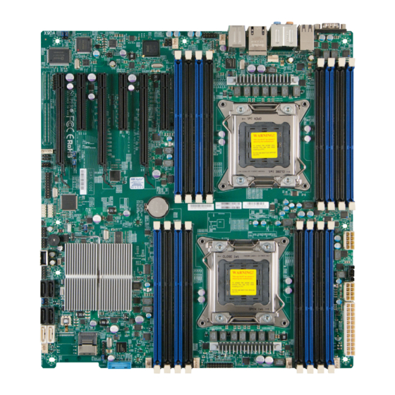
Chapter 1: Overview Chapter 1 Overview Overview Checklist Congratulations on purchasing your computer motherboard from an acknowledged leader in the industry. Supermicro boards are designed with the utmost attention to detail to provide you with the highest standards in quality and performance. Please check that the following items have all been included with your motherboard. - Page 10 X9DAi Motherboard User's Manual Motherboard Image Note: All graphics shown in this manual were based upon the latest PCB Revision available at the time of publishing of the manual. The motherboard you've received may or may not look exactly the same as the graphics shown in this manual.
-
Page 11: Motherboard Layout
Chapter 1: Overview Motherboard Layout USB2.0 USB3.0 7.1 Audio 0/1/2/3 LAN1/2 COM1 FAN5 FAN4 KB/MS S I/O FAN7 (CPU2 Fan) JIPMB1 JBR1 CLK Buffer 1394a Battery X9DAi CTRL Rev. 1.02 Intel C602 JBT1 JOH1 BIOS I-SAS/ SATA0~3 USB3.0 2/3 Note : For the latest CPU/Memory updates, please refer to our website at http://www.supermicro.com/products/motherboard/ for details. - Page 12 X9DAi Motherboard User's Manual X9DAi Quick Reference USB2.0 USB3.0 7.1 Audio 0/1/2/3 LAN1/2 COM1 FAN5 FAN4 KB/MS S I/O FAN7 (CPU2 Fan) JIPMB1 JBR1 CLK Buffer 1394a Battery X9DAi CTRL Rev. 1.02 Intel C602 JBT1 JOH1 BIOS I-SAS/ SATA0~3 USB3.0 2/3 Notes: •...
-
Page 13: Default Setting
Chapter 1: Overview X9DAi Jumpers Jumper Description Default Setting J29/J30 SMB Enable Pins 1-2 (Enabled) JBT1 Clear CMOS See Chapter 3 C1/JI SMBus to PCI-E Slots Pins 2-3 (Normal) JPI1 IEEE1394a Enable Pins 1-2 (Enabled) JPL1/2 GLAN1/GLAN2 Enable Pins 1-2 (Enabled) JWD1 Watch Dog Pins 1-2 (Reset) - Page 14 X9DAi Motherboard User's Manual LAN1/2 G-bit Ethernet Ports 1/2 Onboard Buzzer (Internal Speaker) STBY1 Standby Power Header T-SGPIO 1/2 Serial-Link General_Purpose IO Headers 1/2 USB 2.0 0/1/2/3 Back Panel USB 2.0 Ports 0/1/2/3 USB 2.0 4, 5/6 Front Panel Accessible USB 2.0 Connections 4, 5/6 USB 3.0 0/1 Back Panel USB 3.0 Ports 0/1 USB 3.0 2/3...
-
Page 15: Motherboard Features
Chapter 1: Overview Motherboard Features • Dual Intel LGA 2011 E5-2600 Series Processors ® (Socket R); each processor supports two full-width Intel QuickPath Interconnect (QPI) links (with support of up to 8.0 GT/s per QPI link) • Memory Integrated memory controller supports: •... -
Page 16: Peripheral Devices
X9DAi Motherboard User's Manual Peripheral USB Devices Devices • Four (4) USB 3.0 ports: USB 3.0 Backplane Ports 0/1*, USB 3.0 Front Accessible Connections 2/3) • Seven (7) USB 2.0 Connections: Four (4): Backplane USB 2.0 (Ports 0~3), two (2): Front-Accessible (USB 4, USB 5/6), and •... - Page 17 Chapter 1: Overview PC Health CPU Monitoring • Monitoring Onboard voltage monitors for 1.8V, +3.3V, 3.3VSB, +5V Standby, 1.35V, 1.5V, Chipset Voltage, and Battery Voltage. • CPU 7-Phase switching voltage regulator • CPU/System overheat LED and control • CPU Thermal Trip support •...
- Page 18 X9DAi Motherboard User's Manual #1-4 #0-4 #1-3 #0-3 #1-2 #0-2 #1-1 E5-2600 E5-2600 #0-1 8 SNB CORE 8 SNB CORE 8GT/s DDR3 DDR3 DMI2 #2 #1B #3 #2 #1 DMI2 8GT/s PCI-Ex8 G3 PCI-E X16 G3 PCI-Ex16 G3 PCI-E X4 G3 PCI-E x8 G3 PCI-E x16 G3 DMI2...
-
Page 19: Processor And Chipset Overview
Chapter 1: Overview Processor and Chipset Overview Built upon the functionality and the capability of the Intel E5-2600 Series Proces- sors (Socket R) and the C602 chipset, the X9DAi motherboard provides the perfor- mance and feature sets required for dual_processor-based workstation platforms. With support of Intel QuickPath interconnect (QPI) Technology, the X9DAi offers point-to-point serial interconnect interface with a transfer speed of up to 8.0 GT/s, providing superb system performance. -
Page 20: Special Features
X9DAi Motherboard User's Manual Special Features Recovery from AC Power Loss The Basic I/O System (BIOS) provides a setting that determines how the system will respond when AC power is lost and then restored to the system. You can choose for the system to remain powered off (in which case you must press the power switch to turn it back on), or for it to automatically return to the power-on state. -
Page 21: Acpi Features
Chapter 1: Overview to provide you with warnings when the system/CPU temperatures, CPU voltages and fan speeds go beyond a predefined range. ACPI Features ACPI stands for Advanced Configuration and Power Interface. The ACPI specifica- tion defines a flexible and abstract hardware interface that provides a standard way to integrate power management features throughout a PC system, including its hardware, operating system and application software. -
Page 22: Super I/O
X9DAi Motherboard User's Manual It is strongly recommended that you use a high quality power supply that meets ATX power supply Specification 2.02 or above. It must also be SSI compliant. (For more information, please refer to the website at http://www.ssiforum.org/). Additionally, in areas where noisy power transmission is present, you may choose to install a line filter to shield the computer from noise. -
Page 23: Chapter 2 Installation
Chapter 2: Installation Chapter 2 Installation Static-Sensitive Devices Electrostatic Discharge (ESD) can damage electronic com ponents. To avoid dam- aging your system board, it is important to handle it very carefully. The following measures are generally sufficient to protect your equipment from ESD. Precautions •... -
Page 24: Processor And Heatsink Installation
X9DAi Motherboard User's Manual Processor and Heatsink Installation Warning: When handling the processor package, avoid placing direct pressure on the label area. Notes: Always connect the power cord last, and always remove it before adding, removing or changing any hardware components. Make sure that you in- stall the processor into the CPU socket before you install the CPU heatsink. - Page 25 Chapter 2: Installation 2. Press the second load lever labeled 'Close 1st' to release the load plate that covers the CPU socket from its locking position. Pull lever away from Press down on Load the socket Lever 'Close 1st' 3. With the 'Close 1st' lever fully retracted, gently push down on the 'Open 1st' lever to open the load plate.
- Page 26 X9DAi Motherboard User's Manual 1. Using your thumb and the index finger, remove the 'WARNING' plastic cap from the socket. 2. Use your thumb and index finger to hold the CPU on its edges. Align the CPU keys, which are semi-circle cutouts, against the socket keys. Socket Keys CPU Keys 3.
- Page 27 Chapter 2: Installation 4. With the CPU inside the socket, inspect the four corners of the CPU to make sure that the CPU is properly installed. 5. Close the load plate with the CPU inside the socket. Lock the 'Close 1st' lever first, then lock the 'Open 1st' lever second.
-
Page 28: Installing A Passive Cpu Heatsink
X9DAi Motherboard User's Manual Installing a Passive CPU Heatsink 1. Do not apply any thermal grease to the heatsink or the CPU die -- the re- quired amount has already been applied. 2. Place the heatsink on top of the CPU so that the four mounting holes are aligned with those on the Motherboard's and the Heatsink Bracket under- neath. -
Page 29: Removing The Heatsink
Chapter 2: Installation Removing the Heatsink Warning: We do not recommend that the CPU or the heatsink be removed. However, if you do need to uninstall the heatsink, please follow the instruc- tions below to uninstall the heatsink to prevent damage done to the CPU or the CPU socket. -
Page 30: Installing And Removing The Memory Modules
X9DAi Motherboard User's Manual Installing and Removing the Memory Modules Note: Check Supermicro's Website for recommended memory modules. CAUTION Exercise extreme care when installing or removing DIMM modules to prevent any possible damage. Installing & Removing DIMMs 1. Insert the desired number of DIMMs into the memory slots, starting with P1- DIMM #1A. - Page 31 Chapter 2: Installation Memory Support for the X9DAi Motherboard The X9DAi Motherboard supports up to 512 GB of DDR3 Registered/Load Reduced ECC or Unbuffered ECC/Non-ECC DDR3 1600/1333/1066/800 MHz memory mod- ules in 16 DIMM slots. For the latest memory updates, please refer to our website a at http://www.supermicro.com/products/motherboard.
- Page 32 X9DAi Motherboard User's Manual Intel E5-2600 Series Processor UDIMM Memory Support Ranks Per Memory Capacity Speed (MT/s) and Voltage Validated by Slot per DIMM & Per DIMM Channel (SPC) and DIMM Per Channel (DPC) Data Width 1 Slot Per 2 Slots Per Channel (See the Note below) Channel 1DPC...
- Page 33 Chapter 2: Installation Intel E5-2600 Series Processor LRDIMM Memory Support Ranks Per Memory Capacity Speed (MT/s) and Voltage Validated DIMM & Data Per DIMM by Slot per Channel (SPC) and Width DIMM Per Channel (DPC) 1 Slot Per 2 Slots Per (See the Note Channel Channel...
-
Page 34: Motherboard Installation
X9DAi Motherboard User's Manual Motherboard Installation All motherboards have standard mounting holes to fit different types of chassis. Make sure that the locations of all the mounting holes for both motherboard and chassis match. Although a chassis may have both plastic and metal mounting fas- teners, metal ones are highly recommended because they ground the motherboard to the chassis. -
Page 35: Installing The Motherboard
Chapter 2: Installation Installing the Motherboard 1. Install the I/O shield into the chassis. 2. Locate the mounting holes on the motherboard. 3. Locate the matching mounting holes on the chassis. Align the mounting holes on the motherboard against the mounting holes on the chassis. 4. -
Page 36: Control Panel Connectors And I/O Ports
X9DAi Motherboard User's Manual Control Panel Connectors and I/O Ports The I/O ports are color coded in conformance with the PC 99 specification. See the picture below for the colors and locations of the various I/O ports. Back Panel Connectors and I/O Ports X9DAi Rev. -
Page 37: Serial Ports
Chapter 2: Installation Serial Ports Serial COM Port Pin Definitions One COM connection (COM1) is lo- Pin # Definition Pin # Definition cated on the Backplane I/O panel on the motherboard. See the table on the right for pin definitions. Ground Ethernet Ports LAN Ports Pin Definition... -
Page 38: Atx Ps/2 Keyboard/Mouse Ports
X9DAi Motherboard User's Manual ATX PS/2 Keyboard/Mouse PS/2 Keyboard/Mouse Pin Ports Definitions PS2 Keyboard PS2 Mouse The ATX PS/2 keyboard and Pin# Definition Pin# Definition PS/2 mouse are located next to KB Data Mouse Data the Back Panel LAN ports 1/2 on No Connection No Connection the motherboard. -
Page 39: Universal Serial Bus (Usb)
Chapter 2: Installation Universal Serial Bus (USB) Four Universal Serial Bus 2.0 ports (USB 2.0 Ports 0~3) are located on the I/O back panel. In addition, two USB 3.0 Ports (USB 3.0 Ports 0/1) are also located on the backplane. Additionally, two USB 2.0 ports (USB 2.0 Ports 4, 5/6), a Type A USB, and two USB 3.0 ports (USB 3.0 Ports 2/3) are used to provide front chassis access. -
Page 40: (Back_Panel) High Definition Audio (Hd Audio)
X9DAi Motherboard User's Manual (Back_Panel) High Definition Audio (BP) HD Audio (HD Audio) Conn# Signal This motherboard features a 7.1 Chan- SPDIF_Out nel High Definition Audio (HDA) codec Surround_Out that provides 8 DAC channels. The HD CEN/LFE_Out Audio connections simultaneously sup- Mic_In ports multiple-streaming 7.1 sound play- Line_Out back independent stereo output through Line_In... -
Page 41: Front Control Panel
Chapter 2: Installation Front Control Panel JF1 contains header pins for various buttons and indicators that are normally lo- cated on a control panel at the front of the chassis. These connectors are designed specifically for use with Supermicro's server chassis. See the figure below for the descriptions of the various control panel buttons and LED indicators. -
Page 42: Front Control Panel Pin Definitions
X9DAi Motherboard User's Manual Front Control Panel Pin Definitions NMI Button NMI Button Pin Definitions (JF1) The non-maskable interrupt button Pin# Definition header is located on pins 19 and 20 Control of JF1. Refer to the table on the right Ground for pin definitions. Power LED Power LED Pin Definitions (JF1) The Power LED connection is located... -
Page 43: Hdd Led
Chapter 2: Installation HDD LED HDD LED Pin Definitions (JF1) The HDD LED connection is located Pin# Definition on pins 13 and 14 of JF1. Attach a 3.3V Standby cable here to indicate HDD activ- HD Active ity. See the table on the right for pin definitions. -
Page 44: Overheat (Oh)/Fan Fail Led
X9DAi Motherboard User's Manual Overheat (OH)/Fan Fail LED OH/Fan Fail/PWR Fail LED Pin Definitions (JF1) Connect an LED cable to pins 7 and 8 Pin# Definition of JF1 to provide advanced warnings of chassis overheating and fan failure. OH/Fan Fail LED) Refer to the table on the right for pin definitions. -
Page 45: Reset Button
Chapter 2: Installation Reset Button Reset Button Pin Definitions (JF1) The Reset Button connection is located Pin# Definition on pins 3 and 4 of JF1. Attach it to a Reset hardware reset switch on the computer Ground case. Refer to the table on the right for pin definitions. -
Page 46: Connecting Cables
X9DAi Motherboard User's Manual Connecting Cables ATX Power 24-pin Connector Pin Definitions Pin# Definition Pin # Definition Power Connectors +3.3V +3.3V -12V +3.3V A 24-pin main power supply connector(J22) and two 8-pin CPU PWR connectors PS_ON (JPWR1/2) are located on the motherboard. These power connectors meet the SSI EPS 12V specification. -
Page 47: Fan Headers
Chapter 2: Installation Fan Headers Fan Header Pin Definitions This motherboard has eight system/CPU Pin# Definition fan headers (Fan 1~Fan 7, and Fan A) Ground on the motherboard. All these 4-pin fans +12V headers are backward compatible with Tachometer the traditional 3-pin fans. The fan speeds Thermal Manage- are controlled by firmware thermal man- ment... -
Page 48: Internal Speaker
X9DAi Motherboard User's Manual Internal Speaker Internal Buzzer (SP1) Pin Definition The Internal Speaker, located at SP1, Pin# Definitions can be used to provide audible indica- Pin 1 Pos. (+) Beep In tions for various beep codes. See the Pin 2 Neg. -
Page 49: Tpm Header/Port 80 Header
Chapter 2: Installation TPM Header/Port 80 Header TPM/Port 80 Header Pin Definitions A Trusted Platform Module/Port 80 Pin # Definition Pin # Definition header is located at JTPM1 to provide LCLK TPM support and Port 80 connection. LFRAME# <(KEY)> Use this header to enhance system LRESET# +5V (X) performance and data security. -
Page 50: Power Smb
X9DAi Motherboard User's Manual Power SMB (I C) Connector PWR SMB Pin Definitions Power System Management Bus (I Pin# Definition Connector (JPI C1) monitors power Clock supply, fan and system temperatures. Data See the table on the right for pin PWR Fail definitions. -
Page 51: T-Sgpio 1/2 Headers
Chapter 2: Installation T-SGPIO 1/2 Headers T-SGPIO Pin Definitions Two SGPIO (Serial-Link General Pin# Definition Definition Purpose Input/Output) headers are located on the motherboard. These Ground Data headers support Serial_Link interface Load Ground for onboard SATA connections. See Clock the table on the right for pin defini- Note: NC= No Connection tions. -
Page 52: Spdif_In/Spdif_Out Headers
X9DAi Motherboard User's Manual SPDIF_In/SPDIF_Out Headers SPDIF_In SPDIF_Out Pin Definitions Pin Definitions The SPDIF_In (JSPDIF_In) and SP- Pin# Definition Pin# Definition DIF_Out (JSPDIF_Out) headers are S/PDIF_In S/PDIF_Out located next to the GLAN Controller Ground Ground on the motherboard. Place a cap on each header for audio support. -
Page 53: Overheat/Fan Fail Led
Chapter 2: Installation Overheat/Fan Fail LED OH/Fan Fail LED Status The JOH1 header is used to connect State Message an LED indicator to provide warnings Solid Overheat of chassis overheating and fan failure. Blinking Fan Fail This LED will blink when a fan failure occurs. -
Page 54: Jumper Settings
X9DAi Motherboard User's Manual Jumper Settings Explanation of Jumpers Connector Pins To modify the operation of the mother- board, jumpers can be used to choose between optional settings. Jumpers cre- Jumper ate shorts between two pins to change the function of the connector. Pin 1 is identified with a square solder pad Setting on the printed circuit board. -
Page 55: Cmos Clear
Chapter 2: Installation CMOS Clear JBT1 is used to clear CMOS. Instead of pins, this "jumper" consists of contact pads to prevent accidental clearing of CMOS. To clear CMOS, use a metal object such as a small screwdriver to touch both pads at the same time to short the connection. Always remove the AC power cord from the system before clearing CMOS. -
Page 56: Ieee 1394A Enable
X9DAi Motherboard User's Manual IEEE 1394a Enable 1394a Enable/Disable Jumper Settings JPI1 allows you to enable or disable Both Jumpers Definition the onboard IEEE 1394a support. The Pins 1-2 Enabled default position is on pins 1 and 2 to Pins 2-3 Disabled use 1394_1 and 1394_2 connections. -
Page 57: Onboard Led Indicators
Chapter 2: Installation Onboard LED Indicators GLAN LEDs Activity LED Link LED Two LAN ports (LAN 1/LAN 2) are located Rear View (when facing the on the IO Backplane of the motherboard. rear side of the chassis) Each Ethernet LAN port has two LEDs. The LAN 1/LAN 2 Activity LED (Right) green LED indicates activity, while the other LED State... -
Page 58: Serial Ata Connections
X9DAi Motherboard User's Manual Serial ATA Connections Serial ATA Ports Serial ATA Pin Definitions Two SATA3 Ports (I-SATA0/1), colored in Pin# Definition white, and four SATA2 Ports (I-SATA2~5) Ground are located on the motherboard. In addi- TX_P tion, four SAS/SATA ports (I-SAS/SATA TX_N 0~3) are also located on the motherboard. -
Page 59: Chapter 3 Troubleshooting
Chapter 3: Troubleshooting Chapter 3 Troubleshooting Troubleshooting Procedures Use the following procedures to troubleshoot your system. If you have followed all of the procedures below and still need assistance, refer to the ‘Technical Support Procedures’ and/or ‘Returning Merchandise for Service’ section(s) in this chapter. Note: Always disconnect the power cord before adding, changing or installing any hardware components. -
Page 60: No Video
X9DAi Motherboard User's Manual No Video 1. If the power is on, but you have no video, remove all the add-on cards and cables. 2. Use the speaker to determine if any beep codes exist. Refer to Appendix A for details on beep codes. System Boot Failure If the system does not display POST or does not respond after the power is turned on, check the following:... -
Page 61: Memory Errors
Chapter 3: Troubleshooting Memory Errors When a No-Memory Beep Code is issued by the system, check the following: 1. Make sure that the memory modules are compatible with the system and that the DIMM modules are properly and fully installed. (For memory compatibility, refer to the Memory Compatibility Chart posted on our Website @ http://www. - Page 62 X9DAi Motherboard User's Manual within the normal range. Also check the front panel Overheat LED, and make sure that the Overheat LED is not on. 5. Adequate power supply: Make sure that the power supply provides adequate power to the system. Make sure that all power connectors are connected. Please refer to our website for more information on minimum power require- ment.
-
Page 63: Technical Support Procedures
Chapter 3: Troubleshooting Technical Support Procedures Before contacting Technical Support, please take the following steps. Also, please note that as a motherboard manufacturer, Supermicro also sells motherboards through its channels, so it is best to first check with your distributor or reseller for troubleshooting services. -
Page 64: Battery Removal And Installation
X9DAi Motherboard User's Manual Battery Removal and Installation Battery Removal To remove the onboard battery, follow the steps below: 1. Power off your system and unplug your power cable. 2. Locate the onboard battery as shown below. 3. Using a tool such as a pen or a small screwdriver, push the battery lock out- wards to unlock it. -
Page 65: Battery Removal
Chapter 3: Troubleshooting Battery Removal and Installation Battery Removal To remove the onboard battery, follow the steps below: 1. Power off your system and unplug your power cable. 2. Locate the onboard battery as shown below. 3. Using a tool such as a pen or a small screwdriver, push the battery lock out- wards to unlock it. - Page 66 X9DAi Motherboard User's Manual Frequently Asked Questions Question: What are the various types of memory that my motherboard can support? Answer: The motherboard supports Registered ECC DDR3 DIMM modules. To enhance memory performance, do not mix memory modules of different speeds and sizes.
-
Page 67: Chapter 4 Bios
Chapter 4: AMI BIOS Chapter 4 BIOS Introduction This chapter describes the AMI BIOS Setup utility for the X9DAi. It also provides the instructions on how to navigate the AMI BIOS Setup utility screens. The AMI ROM BIOS is stored in a Flash EEPROM and can be easily updated. Starting BIOS Setup Utility To enter the AMI BIOS Setup utility screens, press the <Del>... -
Page 68: Starting The Setup Utility
X9DAi Motherboard User's Manual Note: For AMI UEFI BIOS Recovery, please refer to the UEFI BIOS Re- covery User Guide posted @http://www.supermicro.com/support/manuals/. Starting the Setup Utility Normally, the only visible Power-On Self-Test (POST) routine is the memory test. As the memory is being tested, press the <F2> key to enter the main menu of the AMI BIOS Setup utility. - Page 69 Chapter 4: AMI BIOS System Date This item displays the system date in Day MM/DD/YY format (e.g. Wed 10/12/2011). System Time This item displays the system time in HH:MM:SS format (e.g. 15:32:52). X9DAi SMC Version This item displays the SMC version of the BIOS ROM used in this system. SMC Build Date This item displays the date that the BIOS Setup utility was built.
-
Page 70: 4-3 Advanced Setup Configurations
X9DAi Motherboard User's Manual 4-3 Advanced Setup Configurations Use the arrow keys to select Advanced Setup and press <Enter> to access the following submenu items. Boot Features Quiet Boot This feature allows the user to select bootup screen display between POST mes- sages and the OEM logo. - Page 71 Chapter 4: AMI BIOS Interrupt 19 Capture Interrupt 19 is the software interrupt that handles the boot disk function. When this item is set to Enabled, the ROM BIOS of the host adaptors will "capture" Interrupt 19 at bootup and allow the drives that are attached to these host adaptors to function as bootable disks.
- Page 72 X9DAi Motherboard User's Manual • Minimum CPU Speed • Processor Cores • Intel HT (Hyper-Threading) Technology • Intel VT-x Technology • L1 Data Cache • L1 Code Cache • L2 Cache • L3 Cache CPU Speed This item displays the speed of the CPU installed in Socket 0. 64-bit This item indicates if the CPU installed in Socket 0 supports 64-bit technology.
- Page 73 Chapter 4: AMI BIOS codes to overwhelm the processor or damage the system during an attack. The default is Enabled. (Refer to Intel and Microsoft Web sites for more information.) Hardware Prefetcher (Available when supported by the CPU) If set to Enabled, the hardware prefetcher will prefetch streams of data and in- structions from the main memory to the L2 cache to improve CPU performance.
- Page 74 X9DAi Motherboard User's Manual Select Enabled to support the Low-power Compliance Mode for Energy-using Products (EuP). The options are Enable and Disable. CPU Power Management Configuration This submenu allows the user to configure the following CPU Power Manage- ment settings. Power Technology Select Energy Efficiency to support power-saving mode. Select Custom to cus- tomize system power settings.
-
Page 75: North Bridge
Chapter 4: AMI BIOS Factory Long Duration Power Limit This item displays the power limit set by the manufacturer during which long duration power is maintained. Long Duration Power Limit This item displays the power limit set by the manufacturer during which long duration power is maintained. - Page 76 X9DAi Motherboard User's Manual Intel I/OAT ® The Intel I/OAT (I/O Acceleration Technology) significantly reduces CPU over- head by leveraging CPU architectural improvements, freeing the system resource for other tasks. The options are Disabled and Enabled. DCA Support Select Enabled to use Intel's DCA (Direct Cache Access) Technology to improve data transfer efficiency.
- Page 77 Chapter 4: AMI BIOS IOU3-PCIe Port If this feature allows the user to set the bus speed between the IOU3 and the PCI-Exp port. The options are x4x4x4x4, x4x4x8, x8x4x4, x8x8, and x16. The default for IOH 1 is x16. The default for IOH 2 is x8x8. Port 3A Link Speed Select GEN1 to enable PCI-Exp Generation 1 support for Port 3A.
- Page 78 X9DAi Motherboard User's Manual Mirroring This item displays if memory mirroring is supported by the motherboard. Sparing This item displays if memory sparing can be supported by the motherboard. DIMM Information The status of the memory modules will be displayed as detected by the BIOS. Memory Mode When Independent is selected, all DIMMs are available to the operating system.
- Page 79 Chapter 4: AMI BIOS Force DDR3-800, Force DDR3-1066, Force DDR3-1333, Force DDR3-1600 and Force SPD. Channel Interleaving This feature selects from the different channel interleaving methods. The options are Auto, 1 Way, 2 Way, 3, Way, and 4 Way. Rank Interleaving This feature allows the user to select a rank memory interleaving method.
- Page 80 X9DAi Motherboard User's Manual OLTT (Open Loop Thermal Throttling) Peak BW (Bandwidth) % This item sets a percentage of the peak bandwidth allowed for Open Loop Thermal Throttling. The range is between 25% and 100%. The default settling is 50 (%). South Bridge Configuration This feature allows the user to configure the settings for the Intel PCH chip.
- Page 81 Chapter 4: AMI BIOS Audio Configuration Azalia HD (High Definition) Audio Select Enabled to enable support for Azalia High Definition Audio. The options are Enabled and Disabled. Azalia Internal HDMI Decode Select Enabled to enable support for Azalia High Definition Muliti-Media Interface Decode. The options are Enabled and Disabled. SATA Configuration When this submenu is selected, the AMI BIOS automatically detects the presence of IDE or SATA devices and displays the following items.
- Page 82 X9DAi Motherboard User's Manual Port 0~5 Hot Plug Select Enabled to enable hot-plug support for a particular port, which will allow the user to change a hardware component or device without shutting down the system. The options are Enabled and Disabled. Staggered Spin Up Select Enabled to enable Staggered Spin-up support to prevent excessive power consumption caused by multiple HDDs spinning-up...
- Page 83 Chapter 4: AMI BIOS This feature appears when Thermal Management is set to Enabled. Select Enabled to support ME SMBus (Management Engine System Management Bus) reporting. The options are Enabled and Disabled. If set to Enabled, the following items appear: PCH Temp Read, CPU Energy Read, CPU Temp Read Set the above items to Enabled to activate these monitors.
- Page 84 X9DAi Motherboard User's Manual Maximum Payload Select Auto to allow the system BIOS to automatically set the maximum payload value for a PCI-E device to enhance system performance. The options are Auto, 128 Bytes, 256 Bytes, 512 Bytes, 1024 Bytes, 2048 Bytes, and 4096 Bytes. Maximum Read Request Select Auto to allow the system BIOS to automatically set the maximum Read Request size for a PCI-E device to enhance system performance.
-
Page 85: Serial Port Console Redirection
Chapter 4: AMI BIOS Serial Port 0 Configuration The submenus allow the user to configure the following settings for Serial Port 0: Serial Port Select Enabled to enable a serial port specified by the user. The options are Enabled and Disabled. Device Settings This feature indicates whether or not a reset is required for a serial port specified. - Page 86 X9DAi Motherboard User's Manual Terminal Type This feature allows the user to select the target terminal emulation type for Con- sole Redirection. Select VT100 to use the ASCII Character set. Select VT100+ to add color and function key support. Select ANSI to use the Extended ASCII Char- acter Set.
-
Page 87: Console Redirection Settings
Chapter 4: AMI BIOS Recorder Mode Select Enabled to capture the data displayed on a terminal and send it as text messages to a remote server. The options are Disabled and Enabled. Resolution 100x31 Select Enabled for extended-terminal resolution support. The options are Dis- abled and Enabled. - Page 88 X9DAi Motherboard User's Manual Bits Per Second This item sets the transmission speed for a serial port used in Console Redirec- tion. Make sure that the same speed is used in the host computer and the client computer. A lower transmission speed may be required for long and busy lines. The options are 9600, 19200, 57600, and 115200 (bits per second).
-
Page 89: Acpi Setting
Chapter 4: AMI BIOS High - The processor is running hot. This is a 'caution' level since the CPU's 'Tem- perature Tolerance' has been reached (or has been exceeded) and may activate an overheat alarm. The system may shut down if it continues for a long period to prevent damage to the CPU. - Page 90 X9DAi Motherboard User's Manual Trusted Computing (Available if a TPM device is installed) TPM Support Select Enabled on this item and enable the TPM jumper on the motherboard to allow TPM support to improve data integrity and network security. The options are Enable and Disable.
-
Page 91: Event Logs
Chapter 4: AMI BIOS Event Logs Use this feature to configure Event Log settings. Change SMBIOS Event Log Settings This feature allows the user to configure SMBIOS Event settings. Enabling/Disabling Options SMBIOS Event Log Select Enabled to enable SMBIOS (System Management BIOS) Event Logging during system boot. - Page 92 X9DAi Motherboard User's Manual Erasing Settings Erase Event Log Select Enabled to erase the SMBIOS (System Management BIOS) Event Log, which is completed before a event logging is initialized upon system reboot. The options are No, Yes Next Reset, and Yes Every Reset. When Log is Full Select Erase Immediately to immediately erase SMBIOS error event logs that exceed the limit when the SMBIOS event log is full.
-
Page 93: Boot
Chapter 4: AMI BIOS Boot This submenu allows the user to configure the following boot settings for the system. Boot Option Priorities Boot Option #1/ Boot Option #2/ Boot Option #3 Use this feature to specify the sequence of boot device priority. Network Device BBS Priorities, Hard Drive BBS Priorities This option sets the order of the legacy network devices and Hard Disks detected by the motherboard. -
Page 94: Security
X9DAi Motherboard User's Manual Security This menu allows the user to configure the following security settings for the system. Administrator Password Use this feature to set the Administrator Password which is required to enter the BIOS setup utility. The length of the password should be from 3-characters to 8-characters long. -
Page 95: Save & Exit
Chapter 4: AMI BIOS Save & Exit This submenu allows the user to configure the Save and Exit settings for the system. Discard Changes and Exit Select this option to quit the BIOS Setup without making any permanent changes to the system configuration, and reboot the computer. Select Discard Changes and Exit, and press <Enter>. - Page 96 X9DAi Motherboard User's Manual Discard Changes Select this feature and press <Enter> to discard all the changes and return to the BIOS setup. When the dialog box appears, asking you if you want to load previ- ous values, click Yes to load the values previous saved, or click No to keep the changes you've made so far.
-
Page 97: Appendix A Bios Error Beep Codes
Appendix A: BIOS POST Error Codes Appendix A BIOS Error Beep Codes During the POST (Power-On Self-Test) routines, which are performed at each system boot, errors may occur. Non-fatal errors are those which, in most cases, allow the system to continue to boot. - Page 98 X9DAi Motherboard User’s Manual Notes...
-
Page 99: Appendix B Software Installation Instructions
Appendix B: Software Installation Instructions Appendix B Software Installation Instructions B-1 Installing Software Programs After you've installed the operating system, a screen as shown below will appear. You are ready to install software programs and drivers that have not yet been in- stalled. -
Page 100: Configuring Superdoctor Iii
X9DAi Motherboard User's Manual B-2 Configuring SuperDoctor III The SuperDoctor III program is a Web-based management tool that supports remote management capability. It includes Remote and Local Management tools. The local management is called the SD III Client. The SuperDoctor III program included on the CDROM that came with your motherboard allows you to monitor the environment and operations of your system. - Page 101 Appendix B: Software Installation Instructions SuperDoctor III Interface Display Screen-II (Remote Control) Note: The SDIII utility and the user guide can be downloaded from our website at: http://www.supermicro.com/products/accessories/software/ SuperDoctorIII.cfm. For Linux, we will still recommend that you use SuperDoctor II.
- Page 102 X9DAi Motherboard User's Manual Notes...
- Page 103 (Disclaimer Continued) The products sold by Supermicro are not intended for and will not be used in life support systems, medical equipment, nuclear facilities or systems, aircraft, aircraft devices, aircraft/emergency communication devices or other critical systems whose failure to perform be reasonably expected to result in significant injury or loss of life or catastrophic property damage.
Need help?
Do you have a question about the Super X9DAi and is the answer not in the manual?
Questions and answers