
Related Manuals for Sun Microsystems Sun Netra CP3250


Summary of Contents for Sun Microsystems Sun Netra CP3250
- Page 1 Sun Netra CP3250 ™ Blade Server User’s Guide Sun Microsystems, Inc. www.sun.com Part No. 820-5195-11 April 2009, Revision 01 Submit comments about this document at: http://www.sun.com/hwdocs/feedback...
- Page 2 Etats-Unis et dans d’autres pays et licenciée exclusivement par X/Open Company, Ltd. Sun, Sun Microsystems, le logo Sun, Netra, Sun Ray, le logo Netra et le logo Solaris sont des marques de fabrique ou des marques déposées de Sun Microsystems, Inc., ou ses filiales, aux Etats-Unis et dans d’autres pays.
-
Page 3: Table Of Contents
Contents Preface xiii Overview 1–1 Overview 1–2 Features 1–2 Physical Description 1–4 1.3.1 Front Panel Components 1–4 1.3.2 Blade Server Diagram 1–6 System Configurations 1–7 1.4.1 AMC 1–8 1.4.2 Advanced Rear Transition Module 1–8 Hot-Swap Support 1–11 System Components 1–11 1.6.1 Required Hardware Components 1–11 1.6.2... - Page 4 Hot-Swapping the Netra CP3250 Blade Server 2–17 2.3.2 Powering Off the Netra CP3250 Blade Server 2–17 2.3.3 Removing the Netra CP3250 Blade Server 2–18 2.3.4 Powering On the System 2–18 Sun Netra CP3250 Blade Server User’s Guide • April 2009...
- Page 5 2.3.5 Automatic Power-Off Events 2–18 2.3.6 Servicing DIMMs 2–19 2.3.6.1 DIMM Requirements 2–19 2.3.6.2 Installing a DDR2 DIMM 2–21 2.3.6.3 Removing a DDR2 DIMM 2–23 2.3.7 Installing the Optional Compact Flash Card 2–24 2.3.8 Installing Optional AMC 2–27 2.3.9 Adding or Replacing the Battery 2–30 2.3.10 Changing Jumper Settings 2–31 2.3.10.1 Clearing the CMOS Setting Using Jumper 2 2–31...
- Page 6 SAS/SATA 3–9 Software Configuration 4–1 Operating Systems 4–2 Software Updates 4–2 SunVTS Software 4–3 Configuring Sun Netra CP3250 blade server For 1 GbE or 10 GbE Switches 4–4 Configuring and Using BIOS Firmware 5–1 About BIOS Settings 5–2 5.1.1 Navigating BIOS Screens 5–2 5.1.2...
- Page 7 B. Physical Characteristics B–1 Form Factor B–2 Power and Thermal Metrics B–2 Connectors and Pinouts B–2 B.3.1 Front Panel Connectors B–2 B.3.1.1 Ethernet Port B–3 B.3.1.2 USB Ports B–4 B.3.1.3 Serial Port B–5 B.3.2 AMC Connector B–5 B.3.3 Power Connector (Zone 1) B–6 B.3.4 Data Transport Connector (Zone 2) B–8 B.3.5...
- Page 8 Sun Netra CP3250 Blade Server User’s Guide • April 2009...
- Page 9 Figures FIGURE 1-1 Netra CP3250 Blade Server (Front View) 1–4 FIGURE 1-2 Netra CP3250 Blade Server (Component Side View) 1–6 FIGURE 1-3 Netra CP3250 Blade Server in Shelf Enclosure 1–7 FIGURE 1-4 Netra CP3250 Blade Server, Backplane, and Relationship to ARTM 1–9 FIGURE 1-5 Netra CP3250 Blade Server Barcode Labeling 1–14 FIGURE 2-1...
- Page 10 Front Panel USB Connector B–4 FIGURE B-3 Front Panel Serial RJ-45 Connector B–5 FIGURE B-4 Power Distribution Connector (Zone 1) P10 B–6 FIGURE B-5 Zone 2 Connector B–8 FIGURE B-6 Zone 3 Connector B–10 Sun Netra CP3250 Blade Server User’s Guide • April 2009...
- Page 11 Tables TABLE 1-1 I/O Configurations 1–10 TABLE 1-2 FRU ID Areas 1–15 TABLE 2-1 Local Area Network Information 2–5 TABLE 2-2 Netinstall Boot Device Table 2–15 TABLE 2-3 Extra MAC Addresses for Virtual LAN Configuration 2–16 TABLE 2-4 Pin Functions on Jumper 2 2–31 TABLE 5-1 BIOS Setup Screens Summary 5–3 TABLE 5-2...
- Page 12 Sun Netra CP3250 Blade Server User’s Guide • April 2009...
-
Page 13: Preface
Sun Netra™ CP3250 blade server. It also provides detailed information on the system firmware. The Sun Netra CP3250 Blade Server User’s Guide is written for system integration engineers, field applications and service engineers, and others involved in the integration of this blade server into systems. - Page 14 Solaris™ Operating System documentation, which is at: ■ http://docs.sun.com/app/docs/prod/solaris Shell Prompts Shell Prompt C shell machine-name% C shell superuser machine-name# Bourne shell and Korn shell Bourne shell and Korn shell superuser Sun Netra CP3250 Blade Server User’s Guide • April 2009...
-
Page 15: Typographic Conventions
* The settings on your browser might differ from these settings. Related Documentation For additional information about the Sun Netra CP3250 blade server or the Netra CP32x0 advanced rear transition module (ARTM), refer to the following documents The following table lists the documentation for this product. The online documentation is available at: http://docs.sun.com/app/docs/prod/cp3250.brd#hic... - Page 16 Sun Netra™ CP32x0 10GbE 820-3150 PDF, Online Configuration Advanced Rear Transition Module, HTML Dual Port User’s Guide http://docs.sun.com/app/docs/prod/cp32x0.10gbee?l=en#hic Documentation, Support, and Training Sun Function Documentation http://docs.sun.com/ Support http://www.sun.com/support/ Training http://www.sun.com/training/ Sun Netra CP3250 Blade Server User’s Guide • April 2009...
-
Page 17: Sun Welcomes Your Comments
Sun is interested in improving its documentation and welcomes your comments and suggestions. You can submit your comments by going to: http://www.sun.com/hwdocs/feedback Please include the title and part number of your document with your feedback: Sun Netra CP3250 Blade Server User’s Guide, part number 820-5195. Preface xvii... - Page 18 Sun Netra CP3250 Blade Server User’s Guide • April 2009...
-
Page 19: Overview
C H A P T E R Overview This chapter provides an overview of the features, configurations, and system requirements of the Sun Netra CP3250 blade server. This chapter contains the following sections: Section 1.1, “Overview” on page 1-2 ■... -
Page 20: Overview
Overview The Sun Netra CP3250 blade server is a dual-socket quad-core Intel-based ATCA blade for high performance ATCA x86 applications in wireless infrastructure and central office consolidation. This blade server complies with the AdvancedTCA specification and is a new addition to SUN's ATCA product family. - Page 21 Dual USB 2.0/1.1 ports on front panel ■ One 10/100/1000MHBASE-T management port on front panel, with second ■ management LAN sent to ARTM (from BCM 5715C); these are not directly tied into IPM controller. SATA to EIDE master to support one Compact Flash Type II socket up to 16 GB of ■...
-
Page 22: Physical Description
Physical Description 1.3.1 Front Panel Components Netra CP3250 Blade Server (Front View) FIGURE 1-1 Sun Netra CP3250 Blade Server User’s Guide • April 2009... - Page 23 Figure Legend Locking screws Latches Out-of-service (OOS) LED OK LED AMC slot 10/100/1000 Ethernet management port Serial port USB port Reset button Chapter 1 Overview...
-
Page 24: Blade Server Diagram
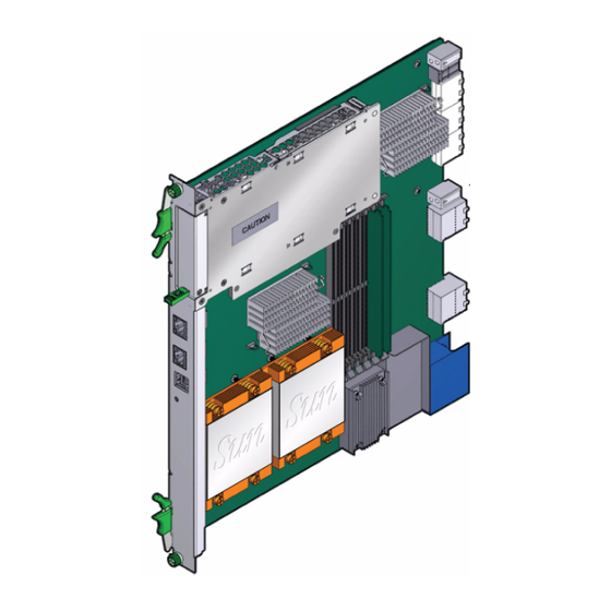
Blade Server Diagram Netra CP3250 Blade Server (Component Side View) FIGURE 1-2 Figure Legend CF card slot Zone 1 power connector Zone 3 connectors DIMMs Zone 2 connectors CPU heatsinks Sun Netra CP3250 Blade Server User’s Guide • April 2009... -
Page 25: System Configurations
System Configurations Sun Netra CP3250 blade servers can be installed into an ATCA shelf (chassis), as shown in . The blade servers can be deployed in various electrical FIGURE 1-3 configurations to suit user requirements. For example, the blade server can be configured to boot from a network as a diskless client with either a front panel or ARTM network connection. -
Page 26: Amc
1.4.1 The Sun Netra CP3250 blade server has one AMC slot, with eight lanes of PCIe, to provide additional I/O to the front panels or to the rear of the enclosure when used with an ARTM. The Sun Netra CP3250 blade server supports AMC mid-height, single wide cards, as defined by the AMC specification. -
Page 27: Figure 1-4 Netra Cp3250 Blade Server, Backplane, And Relationship To Artm
Netra CP3250 Blade Server, Backplane, and Relationship to ARTM FIGURE 1-4 Note – When using the ARTM with the Sun Netra CP3250 blade server, use cables of less than 10 meters in length for serial I/O ports. Chapter 1 Overview... - Page 28 . Sun TABLE 1-1 Microsystems provides the Sun Netra CP3250 blade server and, optionally, a compatible Netra CP32x0 ARTM. The ARTM provides one 10/100/1000BASE-T per second Ethernet RJ-45 port from the host to the rear of the system. This port can be used to accomplish, optionally, a network boot as a diskless client.
-
Page 29: Hot-Swap Support
1.6.1 Required Hardware Components The Sun Netra CP3250 blade server cannot be used as a stand-alone system. It is designed to be used in an ATCA chassis for 8U boards. The minimum hardware requirements needed to use the Sun Netra CP3250 blade server are: ATCA system enclosure for 8U boards (includes shelf, backplane, hub/switch ■... -
Page 30: Optional Hardware Components
1GbE. To use the switch at 10 GbE, perform a one-time configuration procedure, available in the Sun Netra CP3x40 Switch Product Notes (820-3260). 1.6.3 Software Components The following OSs are certified for use on Sun Netra CP3250 blade server: Solaris 10 (05/08) Operating System (Solaris OS) ■ ™... -
Page 31: Technical Support And Warranty
When you call Sun Services, be sure to indicate if the Sun Netra CP3250 blade server was purchased separately, and is not associated with a system. Please have the blade server identification information ready. For proper identification of the blade server, be prepared to give the representative the blade server part number, and serial number. -
Page 32: Viewing The Electronic Blade Server Id Information
Viewing the Electronic Blade Server ID Information The Sun Netra CP3250 blade server can be electronically identified through its IPMI FRU ID PROM, which is accessible through standard fru utilities. The IPMI FRU ID PROM format follows the Intel Specification IPMI Platform Management FRU Information Storage Definition, v1.0 Document, Revision 1.1,... - Page 33 The IPMI FRU ID manufacturing records match Sun part number and serial number labels on the product. For more information about part number and serial number labels, see Section 1.7.1, “Locating the Part Number and Serial Number Information” on page 1-13.
- Page 34 1-16 Sun Netra CP3250 Blade Server User’s Guide • April 2009...
-
Page 35: Hardware Installation And Service
C H A P T E R Hardware Installation and Service This chapter describes the Sun Netra CP3250 blade server hardware installation and service procedures. This chapter contains the following sections: Section 2.1, “Safety and Tool Requirements” on page 2-2 ■... -
Page 36: Safety And Tool Requirements
Netra CP3250 Blade Server Safety and Compliance Guide (820-5198) for specific safety information. Read the following safety statements that are specific to the Sun Netra CP3250 blade server carefully before you install or remove any part of the system. -
Page 37: Materials And Tools Required
■ Antistatic wrist strap ■ Terminal console ■ Serial cable of less than 10 meters in length to connect the Sun Netra CP3250 ■ blade server with a system console Refer to Section 1.6, “System Components” on page 1-11 for information on hardware requirements. -
Page 38: Installing The Blade Server
Your enclosure specifications can support the cooling airflow requirements. ■ The Sun Netra CP3250 blade server fits into a standard ATCA shelf. If your installation requirements are different, contact your field applications engineer. Sun Netra CP3250 Blade Server User’s Guide • April 2009... -
Page 39: Local Network Ip Addresses And Host Names Worksheet
2.2.1.2 Local Network IP Addresses and Host Names Worksheet Collect the information listed in to connect hosts to the LAN. Ask your TABLE 2-1 network administrator for help, if necessary. This information is not needed for a stand-alone installation. Local Area Network Information TABLE 2-1 Information Needed Your Information... -
Page 40: Installation Procedure Summary
Section 2.2.2, “Configuring the Hardware” on page 2-6 through the end of Chapter 2 before installing the blade server. The process to set up and configure a Sun Netra CP3250 blade server in a system includes the following procedures: 1. Configuring the blade server’s physical hardware. -
Page 41: Installing Optional Components
Netra CP32x0 SAS Storage Advanced Rear Transition Module, Dual HD User’s Guide (820-3147) (ARTM-HD) Section B.3, “Connectors and Pinouts” on page B-2 for detailed connector pin assignments for the Sun Netra CP3250 blade server. Chapter 2 Hardware Installation and Service... -
Page 42: Installing The Netra Cp3250 Blade Server In An Atca Shelf
If you install the Sun Netra CP3250 blade server with an ARTM, the ARTM must be installed first. Note – Slots 1 through 6 and 9 through 14 are available for Sun Netra CP3250 blade servers. Slots 7 and 8 are reserved for the switch card. -
Page 43: Figure 2-1 Installing A Netra Cp32X0 Artm
Netra CP32x0 Installing a ARTM FIGURE 2-1 3. Remove the slot filler panel from the selected slot, if necessary. 4. Retrieve the advanced rear transition module (ARTM) from the ship kit. 5. Prepare the rear transition module by opening the injector/ejector latch at the top of the module ( FIGURE 2-2 Chapter 2... -
Page 44: Figure 2-2 Injector/Ejector Latch And Locking Screw On The Artm
8. Push the ARTM into the backplane connectors, and close the latch. 9. Tighten the locking screws to ensure that the module is secured into the ATCA shelf. 2-10 Sun Netra CP3250 Blade Server User’s Guide • April 2009... -
Page 45: Installing The Blade Server Into The Shelf
2.2.3.2 Installing the Blade Server Into the Shelf Note – You can install the Sun Netra CP3250 blade server in any available slot in the ATCA shelf except for slots 7 and 8. 1. If you have installed an advanced rear transition module (ARTM), go to the front of the system and locate the corresponding slot number of the ARTM. -
Page 46: Figure 2-3 Engaging The Netra Cp3250 Blade Server Latch
Engaging the Netra CP3250 Blade Server Latch FIGURE 2-3 7. Tighten the locking screws and the top and the bottom of the Sun Netra CP3250 blade server to ensure that it is secured to the ATCA shelf ( FIGURE 2-2 The blade server is now completely installed and will power on automatically. -
Page 47: Connecting External I/O Cables
CP3250 blade server or the Netra CP32x0 ARTM. Attach asynchronous serial I/O cables from serial communication devices to the ■ RJ-45 serial ports on the Sun Netra CP3250 blade server or Netra CP32x0 ARTM. 2.2.4.1 Connecting Cables to a System Console Running the Solaris 1. -
Page 48: Figure 2-4 Serial Port On The Netra Cp3250 Blade Server
Serial port 3. Use one of the following to establish a full-duplex serial terminal connection with the Sun Netra CP3250 blade server: The tip utility ■ The minicom utility ■ 2-14 Sun Netra CP3250 Blade Server User’s Guide • April 2009... -
Page 49: Connecting Cables To The System Console Not Running The Solaris Os
A telnet utility (Connect to the proper port on a Network Terminal Server to ■ which the Sun Netra CP3250 blade server is connected.) Another suitable serial communications program on the system console ■ For example, if you are using a UNIX system as the system console, at the UNIX... - Page 50 Networking Technolgy 1 GB) The Sun Netra CP3250 blade server supports virtual LAN configuration for the Sun 10 GbE Multithreaded Networking Technolgy ports (MAC addresses 4, 5, 6, and 7). When configured, the virtual LAN feature enables the assignment of multiple MAC address to one port.
-
Page 51: Service Procedures
Service Procedures 2.3.1 Hot-Swapping the Netra CP3250 Blade Server You can remove the Sun Netra CP3250 blade server without powering off the entire chassis by performing these steps. 1. Power off the blade server. Section 2.3.2, “Powering Off the Netra CP3250 Blade Server” on page 2-17. -
Page 52: Removing The Netra Cp3250 Blade Server
Section 2.3.2, “Powering Off the Netra CP3250 Blade Server” on page 2-17. 2. If installed, remove all cables from the front of the Sun Netra CP3250 blade server. 3. Loosen the locking screws to release the blade server from the ATCA shelf. -
Page 53: Servicing Dimms
2.3.6.1 DIMM Requirements The Sun Netra CP3250 blade server supports a total of six DIMMs and the maximum memory capacity of 24 GB (using four 4 GB DIMMs). The Sun Netra CP3250 blade server accommodates the following DIMMs and configurations: Up to six standard DDR2 SDRAM registered/ECC DIMMs ■... -
Page 54: Figure 2-5 Locating Dimm Slots
There are two channels, Channel A and Channel B. DIMMs are identified as A0, B0, A1, B1, A2, and B2. Where Pair 0 would be A0 and B0, and so on. 2-20 Sun Netra CP3250 Blade Server User’s Guide • April 2009... -
Page 55: Installing A Ddr2 Dimm
DIMMs. 1. Access the blade server by performing one of the following procedures: If the Sun Netra CP3250 blade server is installed in an ATCA shelf, remove the ■ blade server from the shelf as explained in Section 2.3.3, “Removing the Netra... -
Page 56: Figure 2-6 Installing A Dimm
The small metal retainer clips on each side of the DIMM slot are spring-loaded, and they should click into place in the notches on the sides of the DIMM. 2-22 Sun Netra CP3250 Blade Server User’s Guide • April 2009... -
Page 57: Removing A Ddr2 Dimm
To remove a DIMM from the Sun Netra CP3250 blade server, perform the following steps: 1. Access the blade server by performing one of the following procedures: If the Sun Netra CP3250 blade server is installed in an ATCA shelf, remove the ■ blade server from the shelf as explained in Section 2.3.3, “Removing the Netra... -
Page 58: Installing The Optional Compact Flash Card
2.3.7 Installing the Optional Compact Flash Card An IDE Compact Flash card can be installed on the Sun Netra CP3250 blade server. The Compact Flash card is not hot-swappable, and there is no access to the Compact Flash card once the Sun Netra CP3250 blade server is installed in an ATCA shelf. -
Page 59: Figure 2-8 Opening The Door To Access Compact Flash
2. Push where indicated on door that provides access to the Compact Flash, then open the door. shows the door. FIGURE 2-8 Opening the Door to Access Compact Flash FIGURE 2-8 3. Locate the Compact Flash connector. The connector is located on the blade server, behind the sheet metal door protecting the AMC slot B1 ( FIGURE 2-9 Chapter 2... -
Page 60: Figure 2-9 Compact Flash Location
Note – Sun Compact Flash cards have a life time of 2,000,000 write/erase cycles. Users are responsible for ensuring that the operating system and applications do not exceed this limitation. 2-26 Sun Netra CP3250 Blade Server User’s Guide • April 2009... -
Page 61: Installing Optional Amc
Sun Netra CP3250 blade server. The blade server contains one AMC slot in which you can install an optional AMC device. An AMC device can be installed and removed via a cutout in the front panel while the Sun Netra CP3250 blade server is installed in the chassis. -
Page 62: Figure 2-10 Removing An Amc Filler Panel
4. Retrieve the AMC from its shipping kit and place it on an antistatic surface. 5. Insert the AMC through the cutout and into the AMC slot ( FIGURE 2-11 2-28 Sun Netra CP3250 Blade Server User’s Guide • April 2009... -
Page 63: Figure 2-11 Installing An Amc
Caution – Do not use excessive force when installing the AMC into the slot. You might damage the AMC connector on the Sun Netra CP3250 blade server, causing permanent damage to the AMC or the blade server. If the AMC does not seat properly when you apply even pressure, remove the AMC and carefully reinstall it. -
Page 64: Adding Or Replacing The Battery
2.3.9 Adding or Replacing the Battery The Sun Netra CP3250 blade server does not ship with the battery. If you want CMOS settings to be preserved in the event of power loss, obtain and install the battery. The battery must be type CR1632, with a minimum of 4ma abnormal charging current rating (for example;... -
Page 65: Changing Jumper Settings
2.3.10 Changing Jumper Settings Jumpers and their switches are located near the heatsink on the blade server. 2.3.10.1 Clearing the CMOS Setting Using Jumper 2 Reset jumper 2 to clear the CMOS settings, which restores the default BIOS settings. Jumper 2 is shown in . -
Page 66: Changing The Oos Led Color Using Jumper 13
1. Remove the jumper housing from the default (amber) position (P2/P3) and move it to the red position (P1/P2). 2. Reinstall the blade server. Use the procedure in Section 2.2.3.2, “Installing the Blade Server Into the Shelf” on page 2-11. 2-32 Sun Netra CP3250 Blade Server User’s Guide • April 2009... -
Page 67: Checking Dip Switch Settings
2.3.11 Checking DIP Switch Settings DIP switch settings are set by default at the factory. The following settings are required for normal operation of the blade server. SW1 Default DIP Switch Settings FIGURE 2-13 SW4 Default DIP Switch Settings FIGURE 2-14 Chapter 2 Hardware Installation and Service 2-33... -
Page 68: Resetting The Netra Cp3250 Blade Server
1. Use a spudger tool or other stylus to press and release the recessed Reset button on the front of the Sun Netra CP3250 blade server ( FIGURE 2-16 2. Confirm the progress of the reset by monitoring the BIOS POST messages. -
Page 69: Figure 2-16 Netra Cp3250 Blade Server Front Panel
Netra CP3250 Blade Server Front Panel FIGURE 2-16 Reset button Chapter 2 Hardware Installation and Service 2-35... - Page 70 2-36 Sun Netra CP3250 Blade Server User’s Guide • April 2009...
-
Page 71: Hardware Architecture
C H A P T E R Hardware Architecture This chapter describes the hardware components and architecture of the Sun Netra CP3250 blade server. This chapter contains the following sections: Section 3.1, “Block Diagram” on page 3-2 ■ Section 3.2, “Intel Processors” on page 3-3 ■... -
Page 72: Block Diagram
Block Diagram Sun Netra CP3250 Blade Server User’s Guide • April 2009... -
Page 73: Intel Processors
Intel Processors The Sun Netra CP3250 blade server supports dual 64-bit low voltage Intel Xeon (Harpertown) processors at 2.13 GHz with 12 MB of L2 cache and a 1066 MHz system bus. This processor is designed for high-performance, low-power communication, storage, and embedded applications. It is built on Intel’s new 65nm topology. -
Page 74: Memory
Memory The Sun Netra CP3250 blade server supports 4-Gbyte registered DDR2-667 memory, for up to 24 Gbytes memory total. When four DIMM slots or less are populated, the DIMM clock rate will be set to the max clock rate of up to 333 Mhz. When six DIMMs slots are populated, the DIMM clock rate will be set to a max clock rate of up to 267 Mhz. -
Page 75: Networking And I/O
Networking and I/O Networking and I/O are provided by the following chips and interconnects: ICH9 I/O controller hub ■ PCI Express Bus ■ LPC bus interface ■ Redundant BIOS ■ Trusted Platform Module ■ Broadcom 5715C Gbit Ethernet chip ■ Sun 10 GbE Multithreaded Networking Technolgy Dual 10-Gbit + Dual 1-Gbit ■... -
Page 76: Lpc Bus Interface
■ 3.5.4 Redundant BIOS The Sun Netra CP3250 blade server provides redundant 1-Mbyte BIOS chips that support redundant BIOS images for increased reliability. The redundant Flash PROMs and SRAM devices are used by the BIOS. Each PROM is an 8 MB flash device. The primary flash device (FWH0) contains the primary BIOS image, factory default settings, and user configured settings. -
Page 77: Trusted Platform Module (Tpm)
Trusted Platform Module (TPM) The Sun Netra CP3250 blade server provides a Trusted Platform Module (TPM) chip, which enables various security features, including hardware and software authentication. This chip is reserved for future use on the Sun Netra CP3250 blade server. 3.5.6... -
Page 78: Broadcom 5715C Gigabit Ethernet
3.6.1 AMC Slot The Sun Netra CP3250 blade server contains one AMC slot, which is available from the front panel. The slot is a single-width, mid-height slot. If needed, AMC I/O connectivity can be accessed from the front panel (depending on the AMC installed) and through the optional advanced rear transition module. -
Page 79: Eide/Ata For Compact Flash
An EIDE/ATA-133 bus is derived from a SATA port on the ICH9 IO Hub via an SPF223A SATA to IDE converter. The Sun Netra CP3250 blade server contains one on-board 50-pin Type II Compact Flash connector for use with a Compact Flash Card. The connector is located so that access to the Compact Flash card is provided only when the card is removed from the ATCA chassis. - Page 80 3-10 Sun Netra CP3250 Blade Server User’s Guide • April 2009...
-
Page 81: Software Configuration
Section 4.1, “Operating Systems” on page 4-2 ■ Section 4.2, “Software Updates” on page 4-2 ■ Section 4.3, “SunVTS Software” on page 4-3 ■ Section 4.4, “Configuring Sun Netra CP3250 blade server For 1 GbE or 10 GbE ■ Switches” on page 4-4... -
Page 82: Operating Systems
Operating Systems The Sun Netra CP3250 blade server has been tested for compatibility with the following operating systems: Solaris 10 (05/08) Operating System (Solaris OS) ■ ™ WindRiver Linux 3.1 ■ RedHat Linux 5.2 ■ Windows 2003 ■ Refer to the Netra CP3250 Blade Server Product Notes (820-5194) for information on Solaris OS and patches. -
Page 83: Sunvts Software
There are similar test suites available for the Linux operating systems. The SunVTS software is a comprehensive software suite that tests and validates the Sun Netra CP3250 blade server by verifying the configuration and function of most hardware controllers and devices on the blade server. -
Page 84: Configuring Sun Netra Cp3250 Blade Server For 1 Gbe Or 10 Gbe Switches
The extended fabric on the Sun Netra CP3250 blade server is capable of operating at either 1 Gbps or 10 Gbps. The Sun Netra CP3250 blade server can be used in the Netra CT 900 server with either the Netra CP3240 10-GbE switch or the Netra CP3140 1-GbE switch. -
Page 85: Configuring And Using Bios Firmware
C H A P T E R Configuring and Using BIOS Firmware This chapter describes how to use the BIOS (Basic Input Output System) to configure the blade server. This chapter contains the following procedures and information: Section 5.1, “About BIOS Settings” on page 5-2 ■... -
Page 86: About Bios Settings
Use the up and down arrow keys to scroll through a screen's menu. Use the Tab key to move across columns. 5.1.2 BIOS Option ROMs The Sun Netra CP3250 blade server has an option ROM for each of the following components: Broadcom BCM 5715C base interfaces ■... -
Page 87: Description Of The Bios Screens
5.1.3 Description of the BIOS Screens contains summary descriptions of the first-level BIOS Setup screens. For more TABLE 5-1 information about the BIOS screens and screen illustrations, see Appendix BIOS Setup Screens Summary TABLE 5-1 Screen Description Main General system information. Advanced Configuration information for the CPUs, IDE, Super I/O, ACPI, Event... -
Page 88: Setting The Boot Device Using Bios Setup Screens
The Boot Device Priority menu is displayed. 7. Select the applicable device and priority. 8. Use the arrow keys to move to the Exit menu, and press Enter. The confirmation dialog box is displayed. Sun Netra CP3250 Blade Server User’s Guide • April 2009... -
Page 89: Setting Supervisor And User Passwords
9. Press Enter to select Ok. The BIOS boots the selected device. The operating system on the selected boot device loads. 10. Configure the operating system by providing a locale, system name, IP address, and other information. Refer to the documentation for your operating system for information on configuring the operating system. -
Page 90: Resetting The System Time And System Date
Use the Solaris BIOS Update Utility or the Linux BIOS Update Utility to implement the updates. For more information, see the Netra CT 900 Server Product Notes (819-1180). Sun Netra CP3250 Blade Server User’s Guide • April 2009... -
Page 91: Secondary Bios Image
Secondary BIOS Image The Sun Netra CP3250 blade server provides dual 1-Mbyte BIOS chips that support redundant BIOS images for increased reliability. The default chip (page 0) acts as the primary BIOS chip and is automatically selected for update during a firmware upgrade. -
Page 92: Perform A Live Firmware Upgrade
You can configure the level of POST testing and some POST display features through the BIOS menus. For more information, see Section 5.10, “Changing POST Options” on page 5-9. Sun Netra CP3250 Blade Server User’s Guide • April 2009... -
Page 93: Changing Post Options
5.10 Changing POST Options These instructions are optional, but you can use them to change the operations that the server performs during POST testing. 1. Initialize the BIOS Setup utility by pressing the F2 key while the system is performing the power-on self-test (POST). The BIOS Main Menu screen is displayed. - Page 94 5-10 Sun Netra CP3250 Blade Server User’s Guide • April 2009...
-
Page 95: Bios Screens
A P P E N D I X BIOS Screens This appendix provides examples of the screens from the BIOS utility. For information on how to access BIOS menus and configure settings, see Chapter... -
Page 96: Figure A-1 Bios Main Menu
BIOS Main Menu FIGURE A-1 Sun Netra CP3250 Blade Server User’s Guide • April 2009... -
Page 97: Figure A-2 Advanced Configuration Menu
Advanced Configuration Menu FIGURE A-2 Appendix A BIOS Screens... -
Page 98: Figure A-3 Cpu Configuration Menu
CPU Configuration Menu FIGURE A-3 Sun Netra CP3250 Blade Server User’s Guide • April 2009... -
Page 99: Figure A-4 Ide Configuration Menu
IDE Configuration Menu FIGURE A-4 Appendix A BIOS Screens... -
Page 100: Figure A-5 Usb Configuration Menu
USB Configuration Menu FIGURE A-5 Sun Netra CP3250 Blade Server User’s Guide • April 2009... -
Page 101: Figure A-6 Event Log Control Menu
Event Log Control Menu FIGURE A-6 Appendix A BIOS Screens... -
Page 102: Figure A-7 Ipmi 2.0 Configuration Menu
IPMI 2.0 Configuration Menu FIGURE A-7 Sun Netra CP3250 Blade Server User’s Guide • April 2009... -
Page 103: Figure A-8 Remote Access Configuration Menu
Remote Access Configuration Menu FIGURE A-8 Appendix A BIOS Screens... -
Page 104: Figure A-9 Pci Option Rom Configuration Menu
PCI Option ROM Configuration Menu FIGURE A-9 A-10 Sun Netra CP3250 Blade Server User’s Guide • April 2009... -
Page 105: Figure A-10 Trusted Computing Menu
Trusted Computing Menu FIGURE A-10 Appendix A BIOS Screens A-11... -
Page 106: Figure A-11 Boot Settings Menu
Boot Settings Menu FIGURE A-11 A-12 Sun Netra CP3250 Blade Server User’s Guide • April 2009... -
Page 107: Figure A-12 Boot Device Priority Configuration Menu
Boot Device Priority Configuration Menu FIGURE A-12 Appendix A BIOS Screens A-13... -
Page 108: Figure A-13 Security Settings Menu
Security Settings Menu FIGURE A-13 A-14 Sun Netra CP3250 Blade Server User’s Guide • April 2009... -
Page 109: Figure A-14 Exit Menu
Exit Menu FIGURE A-14 Appendix A BIOS Screens A-15... - Page 110 A-16 Sun Netra CP3250 Blade Server User’s Guide • April 2009...
-
Page 111: Physical Characteristics
A P P E N D I X Physical Characteristics Specifications for the Sun Netra CP3250 blade server are provided in the following sections: Section B.1, “Form Factor” on page B-2 ■ Section B.2, “Power and Thermal Metrics” on page B-2 ■... -
Page 112: Form Factor
Form Factor The Sun Netra CP3250 blade server is a standard 8-rack unit (8U) factor, single-slot wide. It complies with the board mechanical dimensions that are required by the PICMG 3.0 specification: 322.25 mm x 280 mm (12.7 inches x 11.0 inches) ■... -
Page 113: Ethernet Port
B.3.1.1 Ethernet Port The Ethernet connector is an RJ-45 connector. The controller autonegotiates to either 10 BASE-T, 100 BASE-T, or 1000 BASE-T. shows the Ethernet port connector. FIGURE B-1 Ethernet RJ-45 Connector FIGURE B-1 1 2 3 4 5 6 7 8 provides the eight pin assignments for the Ethernet port connector. -
Page 114: Usb Ports
Front Panel USB Connector FIGURE B-2 lists the USB port connector pin assignments. TABLE B-3 USB Port Pin Assignments TABLE B-2 Signal Name Description +5 VDA (500ma) Data- Data+ Ground Sun Netra CP3250 Blade Server User’s Guide • April 2009... -
Page 115: Serial Port
B.3.1.3 Serial Port shows the connector pin assignments for the front panel serial port. FIGURE B-3 Front Panel Serial RJ-45 Connector FIGURE B-3 1 2 3 4 5 6 7 8 lists the serial port connector pin assignments. TABLE B-3 Mini DIN 8-pin Serial Port Connector Pinouts... -
Page 116: Power Connector (Zone 1
B.3.3 Power Connector (Zone 1) The Sun Netra CP3250 blade server uses a 34-pin Positronic connector as the Zone 1 power distribution connector. It provides the support for the following signals: Two -48 VDC power feeds (four signals each; eight signals total) ■... - Page 117 Power Distribution Connector Pin Assignments (Continued) TABLE B-4 Pin Number Name Description HA5 Hardware Address Bit 5 HA6 Hardware Address Bit 6 HA7/P HA7/P Hardware Address Bit 7 (Odd Parity Bit) SCL_A IPMB Clock, Port A SDA_A IPMB Data, Port A SCL_B IPMB Clock, Port B SDA_B...
-
Page 118: Data Transport Connector (Zone 2
Advanced Rear Transition Module (ARTM) Connector (Zone 3) The Sun Netra CP3250 blade server provides all the I/O connections for rear access through the Zone 3 advanced rear transition module (ARTM) connector. The connector view and the pinout for the Zone 3 connector are shown in FIGURE B-6 Sun Netra CP3250 Blade Server User’s Guide •... -
Page 119: Figure B-6 Zone 3 Connector
The “reserved” pins indicate connector pins that are currently reserved for compatibility to all ARTMs. Do not connect signals to reserved pins. The “no connect” indicates pins that should not be connected by the Sun Netra CP3250 blade server. Zone 3 Connector... -
Page 120: Zone 3 (J30) Connector Pin Assignments
EO_Rx3+) EO_Rx3-) EO_Tx3+ EO_Tx3-) AMC0 RTM_RX18 RTM_RX18 GND RTM_TX RTM_TX GND RTM_RX17 RTM_RX17 + (AMC0 - (AMC0 + (AMC0 - (AMC0 EO_Tx5+) EO_Tx5-) (AMC0 (AMC0 EO_Tx4+) EO_Tx4-) EO_Rx5+ EO_Rx5- B-10 Sun Netra CP3250 Blade Server User’s Guide • April 2009... -
Page 121: Zone 3 (J32) Connector Pin Assignments
J31 Connector Pin Assignments (Continued) TABLE B-6 Row Interface AMC0 RTM_TX20 RTM_TX20 GND RTM_RX RTM_RX GND RTM_TX19 RTM_TX19 + (AMC0 - (AMC0 + (AMC0 - (AMC0 EO_Rx7+) EO_Rx7-) (AMC0 (AMC0 EO_Rx6+) EO_Rx6-) EO_Tx6+ EO_Tx6-) AMC0 Reserved Reserved GND Reserved Reserved GND RTM_RX20 RTM_RX20 + (AMC0 - (AMC0... -
Page 122: Zone 3 (J33) Connector Pin Assignments
PERx6- TRST# Lane PCIe x8 PETx7+ PETx7- PERx7+ PERx7- PCI_RST Lane Reserved No ARTM# PCI_CFG GND Connect Connect Connect Connect Reserved No PS0# Enabled# GND Connect Connect Connect Connect B-12 Sun Netra CP3250 Blade Server User’s Guide • April 2009... -
Page 123: Zone 3 Signal Descriptions
B.3.5.5 Zone 3 Signal Descriptions provides descriptions of the signals listed in the Zone 3 pin assignment TABLE B-10 tables ( through TABLE B-6 TABLE B-9 Zone 3 Signal Descriptions TABLE B-9 Signal Name Description IPMI_SCL_L IPMI bus clock signal, as defined in AMC.0 specification. RTM shall have a pull-up resistor for this signal as indicated in AMC.0 specification. - Page 124 Fabric clock, as defined in AMC.0 specification. Intended to be used for PCI-Express 100 MHz spread spectrum clock. TCK, TMS, TRST#, JTAG signals. Signal direction shall follow AMC.0 specification. TDO, TDI B-14 Sun Netra CP3250 Blade Server User’s Guide • April 2009...
- Page 125 Appendix B Physical Characteristics B-15...
- Page 126 B-16 Sun Netra CP3250 Blade Server User’s Guide • April 2009...
-
Page 127: Shmm Cli And Commands
A P P E N D I X ShMM CLI and Commands This appendix provides information about using the ShMM CLI and most commonly used ShMM commands. This appendix contains the following topics: “Shelf Manager Command-Line Interface” on page 2 ■... -
Page 128: Shelf Manager Command-Line Interface
Pigeon Point Shelf Manager Command Line Interpreter 20: Entity: (d0, 0) Maximum FRU device ID: 20 PICMG Version 2.0 Hot Swap State: M4, Previous: M3, Last State Change Cause: Normal State Change Sun Netra CP3250 Blade Server User’s Guide • April 2009... -
Page 129: Shelf Manager Cli Commands
If started without parameters, clia enters an interactive mode. In that mode, the program repeatedly issues a prompt to the terminal, accepts user input as the next command with parameters, executes that command, and shows the results on the terminal, until the user types the command exit or quit. For example: # clia Pigeon Point Shelf Manager Command Line Interpreter CLI>... - Page 130 Shows value information for a specific sensordata sensor. sensor name (optional) sensor number (optional) IPMB address Shows raw value information for a sensorread specific sensor (ignoring any Sensor Data sensor number Record describing the sensor). Sun Netra CP3250 Blade Server User’s Guide • April 2009...
- Page 131 Shelf Manager CLI Command Summary (Continued) TABLE C-1 Command Parameters Description IPMB address Sets a new level for the fan controlled by setfanlevel the specified FRU. FRU device ID Use clia setfanlevel 20 3 5 to get level the fans to slow down. IPMB address Enables or disables fan trays for cooling setfanpolicy...
- Page 132 Shelf Manager, the following message is issued when a CLI command is executed on the backup Shelf Manager: Running on the Backup Shelf Manager, with limited functionality. Sun Netra CP3250 Blade Server User’s Guide • April 2009...
-
Page 133: Index
Index system console, 2-15 system console for Solaris, 2-13 AMC cards supported, 1-8 chassis. See shelf, 1-7 AMC connectors, B-5 CMOS settings AMC devices clearing, 2-31 additional I/O, 1-8 collecting network information, 2-5 installing, 2-27 Compact Flash installing, 2-24 configurations, I/O, 1-10 barcode labels, locating, 1-13 connectors, B-2 BIOS... - Page 134 1-13 switches, configuring for 1GbE or 10GbE, 4-4 operating system compatibility, 4-2 warranty, 1-13 part number, locating, 1-14 password changing BIOS, 5-5 PCI Express Configuration menu, A-10 pinouts, B-2 Index-2 Sun Netra CP3250 Blade Server User’s Guide • April 2009...
Need help?
Do you have a question about the Sun Netra CP3250 and is the answer not in the manual?
Questions and answers