
Related Manuals for GRASS VALLEY ADVC G1


Summary of Contents for GRASS VALLEY ADVC G1
-
Page 1: User Manual
ADVC G1 User Manual ADVC G1 User Manual June 16, 2011 Copyright © 2011 Grass Valley K.K. All rights reserved. -
Page 2: Copyright Regulations
7. ADVC is a registered trademark of Grass Valley K.K. HDMI, HDMI logo and High-Definition Multimedia Interface are trademarks or registered trademarks of HDMI Licensing LLC. - Page 3 DANGER The following conditions indicate the potential for serious bodily injury or loss of life. Handle the power cable carefully Do not place heavy objects on top of the cord, or place it near hot objects. Doing so may damage the cable and result in fire, electrical shock, or malfunction. Altering the cord, or excessively bending or pulling the cord may result in fire or electrical shock.
- Page 4 Notes on installation Install the product where there is(are) a power socket(s) nearby, and where you can easily shut down the power to the product. Do not operate this product from a power source that supplies more than the specified voltage.
-
Page 5: Fcc Notice
Cet appareil numérique de la classe A est conforme á la norme NMB-003 du Canada. Declaration of Conformity According to FCC Part 15 Responsible Party Name: Grass Valley USA, LLC. Address: 400 Providence Mine Road, Nevada City, CA 95959 Telephone: 530-478-3000 This product may cause interference if used in residential areas. -
Page 6: Read Me First
Grass Valley or an authorized Grass Valley agent. This warranty can be applied only to the original purchaser of the Grass Valley product and is not transferable. Grass Valley, Inc. warrants that for this period the product will be in good working order. - Page 7 équitable (pour des fins privées et non commerciales). Par ailleurs, dans certains cas, la reproduction est interdite sans exception. Grass Valley ne peut en aucun cas être tenu pour responsable des dommages directs ou indirects résultant d’une utilization des ressources capturées.
-
Page 8: Droits D'auteur
Droits d’auteur N’utilisez pas des données vidéo/audio capturées créées par d’autres personnes sans l’autorisation du détenteur du droit, qu’il s’agisse d’une image fixe ou en mouvement, sauf pour votre plaisir personnel. De même, la reproduction de telles données est parfois limitée même pour les loisirs personnels. Veuillez noter que nous sommes dégagés de toute responsabilité... - Page 9 Ne pas installer le produit près dans un endroit chaud N’installez pas le produite dans un endroit exposé à la lumière directe du soleil ou à proximité d’un appareil de chauffage. La chaleur peut s’accumuler causant des brûlures, un incendie ou des dégâts. De même, l’unité peut se déformer ou changer de couleur. Ne pas faire fonctionner le produit en cas de soupçons de panne Si vous remarquez que ce produit est endommagé, faites-le examiner par un personnel d’entretien qualifié.
- Page 10 Ne pas remanier le câble d’alimentation Ne remaniez pas le câble d’alimentation. Si vous le faites, cela peut entraîner un incendie ou un mauvais fonctionnement du produit. Acheminer les câbles de manière adéquate Acheminez le câble d’alimentation et les câbles AV de manière adéquate. S’ils s’accrochent à...
-
Page 11: Fcc Notification
Cet appareil numérique de la classe A est conforme á la norme NMB-003 du Canada. Déclaration de conformité Conformément au paragraphe 15 de la réglementation FCC Nom du responsable: Grass Valley USA, LLC. Address: 400 Providence Mine Road, Nevada City, CA 95959 Téléphone:... - Page 12 (ou de deux ans dans les pays de l’Union européenne) à partir de la date d’achat chez Grass Valley ou chez un agent autorisé de Grass Valley. Cette garantie peut uniquement s’appliquer uniquement à l’acheteur original du produit Grass Valley et n’est pas transférable.
-
Page 13: Operation Environment
- ADVC G1 Unit - AC adapter & Power cable - Manual (This document) 1.3 Website Including ADVC G1, the latest company information is announced at our Website: http://www.grassvalley.com/products The latest drivers utilities, product manuals, FAQs, etc. are also available... - Page 14 Ref IN port. With the two channels of analog balanced audio and the one AES/ EBU digital audio inputs, the ADVC G1 can also be used as an audio embedder, and outputs SDI signal with analog audio embedded. The...
-
Page 15: Part Name And Functions
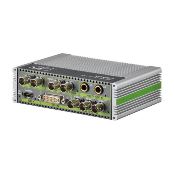
3 Part Name and Functions 3.1 Front panel (1) Power LED Lights when the ADVC G1 is operating. (2) Up Conv. LED Lights in up-conversion mode. (3) SDI OUT 3G/HD/SD-SDI output ports. (4) Ref IN Reference signal input port. The LED is lit when REF is selected for reference signal source, and if the reference signal input via Ref IN can be synchronized. - Page 16 (7) HDMI IN HDMI input port. The LED marked with “V” blinks when HDMI is selected for video input, and the LED is lit when a stable signal input is detected. The LED marked with “A” is lit when HDMI embeded is selected for audio input.
-
Page 17: Rear Panel
Use the switches to choose input/output settings. See page 6 for details. (5) USB port Used for firmware update. Note To connect the DC plug to the ADVC G1, check the direction of the power plug, and set it in the proper direction. -
Page 18: Hardware Settings
4 Hardware Settings 4.1 DIP switches Specifies the SD pedestal. OFF: 7.5 IRE ON: 0 IRE * Available only for SD-Component, Composite, S-Video input mode. Specifies the component level. OFF: SMPTE/EBU N10 ON: Betacam * Available for SD-Component input mode. Specifies the reference signal source. - Page 19 Specifies the image enhance mode. OFF: OFF ON: Image enhance * Detail will be enhanced. SW10 Specifies the noise reduction mode of the video processor. SW11 SW10=ON Auto (for non compressed SW11=ON video) SW10=ON Low (for compressed video) SW11=OFF SW10=OFF High (for highly compressed SW11=ON video)
- Page 20 4.2 INPUT MODE switches VIDEO INPUT MODE switch Specifies the video input. 0: HD analog component 1: SD analog component 2: S-Video 3: Composite 4: HDMI 5: DVI-D 6: DVI-A 7: Reserved 8: Reserved 9: Reserved * The resolution will automatically be detected.
-
Page 21: Display Mode
5 Display Mode Output Input Standard Full screen Flex view 4:3 is displayed same 4:3 is displayed same as Standard mode. as Standard mode. SD resolution Displayed same Displayed same as Standard mode. as Standard mode. HD resolution PC resolution* * The figure above shows the case in which screen resolution 16:10 (WUXGA: 1920x1200) is used. -
Page 22: Specifications
6 Specifications 6.1 Block diagram Sync REF in Genlock separator SD Setup Level SD Component Level CVBS in DIP Switch 3G-SDI Level S-Video in Up-conv mode Display mode Image enhance mode Stream Clean mode SD-Component Video Scaler HD-Component Frame Audio SDI out Rotary Image enhancer... -
Page 23: Hardware Specifications
6.2 Hardware specifications HDMI input Input connector HDMI 1080i 60/59.94/50 1080p 60/59.94/50/30/29.97/25/24/23.98 Input resolution 720p 60/59.94/50 480i/p 60/59.94 576i/p 50 VGA(640x480),SVGA(800x600) XGA(1024x768),SXGA(1280x1024) FWXGA(1360x768) UXGA(1600x1200),WUXGA(1920x1200) PC resolution framerate 60 Hz Input color format YCbCr(4:2:2/4:4:4), RGB(4:4:4) Deep color support Not supported Color format conversion YCbCr 4:2:2 12 bits DVI-D input Input connector... - Page 24 DVI-A input Input connector DVI-I(DVI-A) VGA(640x480),SVGA(800x600) XGA(1024x768),SXGA(1280x1024) Input resolution FWXGA(1360x768) UXGA(1600x1200) Framerate 60 Hz Input color format Color format conversion YCbCr 4:2:2 12 bits Component input Input connectors YPbPr Input resolution 1080i 60/59.94/50 1080p 30/29.97/25/24/23.98 1080PsF 24/23.98 720p 60/59.94/50 486i 59.94 483p 59.94 576i/p 50 Input color format...
- Page 25 S-Video input Input connectors S-Y/S-C (Common with Component-Pb,Pr) Standard NTSC, PAL Input color format YPbPr Color format conversion YCbCr 4:2:2 12 bits SD pedestal 0 IRE, 7.5IRE Audio Input Input connectors Balanced analog (2ch) AES/EBU digital (2ch) HDMI embedded (8ch) * HDMI audio is not available when DVI is chosen for video input.
-
Page 26: Audio Output
Audio output Output connectors SDI embedded * Supports outputting with 8ch multi-audio in HDMI input mode. If AES/Analog is selected, audio will be embedded to 1/2ch. Sample rate 48 kHz Sample size 24 bits(3G/HD), 20 bits(SD) Output level adjust Not supported Video resizing Up conversion Supported... - Page 27 REF Sync Video output Reference signal (BB/HDSync) Internal * REF Sync can be enabled/disabled with DIP SW3. When disabled, or when there is no signal input, the ADVC G1 automatically turns into Internal Sync mode. Format USB2.0 compliant Connector Mini B...
- Page 28 ADVC G1 Input/Output Input Output Connector Framerate Resolution Through UP/720 UP/1080i UP/1080p HDMI 60/59.94 1080i 1080i 720p 1080i 1080p 1080p 1080p 720p 1080i 1080p 720p 720p 720p 1080i 1080p 480i 487i 720p 1080i 1080p 480p 487i 720p 1080i 1080p 640x480p...
- Page 29 Input Output Connector Framerate Resolution Through UP/720 UP/1080i UP/1080p DVI-D 60/59.94 1080i 1080i 720p 1080i 1080p 1080p 1080p 720p 1080i 1080p 720p 720p 720p 1080i 1080p 480p 487i 720p 1080i 1080p 640x480p 487i 720p 1080i 1080p 800x600p 1080p 720p 1080i 1080p 1024x768p 1080p --...
- Page 30 Input Output Connector Framerate Resolution Through UP/720 UP/1080i UP/1080p Component 60/59.94 1080i 1080i 720p 1080i 1080p 1035i 1080i 720p 1080i 1080p 720p 720p 720p 1080i 1080p 486i 487i 720p 1080i 1080p 483p 487i 720p 1080i 1080p 1080i 1080i 720p 1080i 1080p 720p 720p...
- Page 32 F2431103181...